PPPoE Server Lab with Cisco BRAS-Style Termination, VLAN Distribution, and MikroTik NAT
A lab project that simulates a PPPoE-based broadband access network using a Cisco PPPoE Server as the subscriber termination point, Cisco…
PPPoE Server Lab with Cisco BRAS-Style Termination, VLAN Distribution, and MikroTik NAT
A lab project that simulates a PPPoE-based broadband access network using a Cisco PPPoE Server as the subscriber termination point, Cisco distribution switches for VLAN transport, and a MikroTik router as the upstream NAT gateway.
This topology is designed to model how PPPoE subscribers authenticate to a BRAS-style access concentrator, receive IP addresses from a local pool, traverse a VLAN-based switching infrastructure, and then reach an upstream router that provides internet breakout using NAT.
Repositories : https://github.com/ferisigitpratama/pppoeserver.git
Project Overview
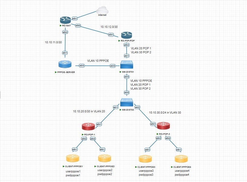
This project simulates a PPPoE access network where subscribers connect to a Cisco PPPoE Server, authenticate using PPP credentials, receive an IP address from a local subscriber pool, and are then routed toward an upstream MikroTik NAT router for internet access.
The lab is divided into three main functional layers:
1. Subscriber Termination Layer
The Cisco PPPoE Server acts as the access concentrator that accepts PPPoE sessions, authenticates users, and dynamically assigns IP addresses to subscribers.
2. Distribution / Transport Layer
Two Cisco switches, SW-DIST01 and SW-DIST02, are used to carry VLAN-based service traffic between the PPPoE server and other parts of the network.
3. Upstream Internet Breakout Layer
A MikroTik router, RO-NAT, acts as the upstream gateway that performs source NAT / masquerade and forwards subscriber traffic toward the upstream network or internet-facing side.
This design reflects a simplified BRAS / BNG-style architecture, where subscriber session management and internet breakout are handled by different devices.
Objectives
This lab was built to demonstrate the key components of a PPPoE-based access service, including:
- PPPoE subscriber authentication and session establishment
- Dynamic IP assignment using a local address pool
- VLAN-based transport across a switching distribution layer
- Routed handoff from the PPPoE server to an upstream NAT router
- Internet breakout using source NAT / masquerade
- A simplified broadband access model similar to an ISP environment
Topology Overview
The lab consists of the following devices:
- PPPOE-SERVER → Cisco router acting as the PPPoE access concentrator / BRAS
- SW-DIST01 → first distribution switch
- SW-DIST02 → second distribution switch
- RO-NAT → MikroTik upstream NAT router
High-Level Topology
PPPoE Client(s)
      |
      | PPPoE Access
      |
+----------------------+
|    PPPOE-SERVER      |
|   Cisco BRAS Router  |
+----------+-----------+
           |
           | VLAN Transport
           |
+----------+-----------+
|       SW-DIST01      |
+----------+-----------+
           |
           | Trunk / Distribution
           |
+----------+-----------+
|       SW-DIST02      |
+----------+-----------+
           |
           | Routed Handoff / Service Extension
           |
+----------+-----------+
|        RO-NAT        |
|   MikroTik Router    |
+----------+-----------+
           |
           | NAT / Internet
           |
        Upstream
IP Addressing Plan
PPPOE-SERVER
InterfaceIP AddressDescriptionEthernet0/011.11.11.1/30PPPoE access-facing interfaceEthernet0/110.10.11.2/30Uplink toward RO-NAT
RO-NAT
InterfaceIP AddressDescriptionether110.10.16.92/28Upstream / WAN sideether210.10.11.1/30Link toward PPPOE-SERVERether310.10.12.1/30Internal / routed segment
PPPoE Subscriber Pool
Pool NameAddress RangeBRAS01-LPG10.10.10.11 - 10.10.10.254
Device Roles
PPPOE-SERVER
PPPOE-SERVER is the subscriber termination router in this lab. It acts as the PPPoE access concentrator and is responsible for:
- receiving PPPoE discovery and session requests,
- authenticating subscribers using locally configured PPP credentials,
- assigning subscriber IP addresses dynamically from a local pool,
- creating PPP sessions using a Virtual-Template interface,
- forwarding subscriber traffic toward the upstream NAT router.
Actual PPPoE Components Used
- BBA Group:
BRAS01-LPG - PPPoE Access Interface:
Ethernet0/0 - Virtual Template:
Virtual-Template1 - Subscriber Pool:
10.10.10.11 - 10.10.10.254 - Authentication:
chap pap - Uplink to NAT:
Ethernet0/1 → 10.10.11.2/30 - Default Route:
0.0.0.0/0 → 10.10.11.1
SW-DIST01
SW-DIST01 acts as the first distribution switch in the topology.
Its role is to:
- connect directly to the PPPoE server,
- place the PPPoE-facing interface in access VLAN 10,
- forward selected service VLANs toward another transport side,
- connect to SW-DIST02 using a trunk carrying VLAN 10, 20, and 30.
Actual Interface Mapping
InterfaceDescriptionModeVLANEthernet0/0PPPOE-SERVER-ETH0/0AccessVLAN 10Ethernet0/1RO-P2P-POP-ETH0/2TrunkVLAN 20,30Ethernet0/3SW-DIST2-ETH0/0TrunkVLAN 10,20,30
SW-DIST02
SW-DIST02 acts as the second distribution / transport switch and extends VLAN connectivity deeper into the topology.
Actual Trunk Configuration
InterfaceModeAllowed VLANsEthernet0/0Trunk10,20,30Ethernet0/1Trunk10,20Ethernet0/2Trunk10,30
This switch is used to continue service transport and simulate a larger switching domain in the access network.
RO-NAT
RO-NAT is the upstream MikroTik router responsible for internet breakout and source NAT.
Its role is to:
- receive routed subscriber traffic from the PPPoE server,
- perform masquerade / source NAT,
- forward traffic toward the upstream network,
- maintain static routes back to subscriber and internal lab networks.
Actual Routing / NAT Role
- Uplink / WAN:
10.10.16.92/28onether1 - Link to PPPOE-SERVER:
10.10.11.1/30onether2 - Masquerade enabled for outbound traffic
- Static route to subscriber pool:
10.10.10.0/24 via 10.10.11.2
Additional routes in the lab include:
10.20.10.0/30 via 10.12.10.210.30.10.0/30 via 10.12.10.2
PPPoE Service Design
The PPPoE service is implemented on the Cisco router using a BBA group and a Virtual-Template.
PPPoE Access Interface
The PPPoE service is enabled on:
Ethernet0/0- IP address:
11.11.11.1/30
This interface listens for subscriber PPPoE discovery and session requests.
BBA Group
The BBA group used in this project is:
bba-group pppoe BRAS01-LPG
This group references the virtual template used to instantiate subscriber PPP sessions.
Virtual Template
Subscriber sessions are created using:
Virtual-Template1
This template:
- uses ip unnumbered Ethernet0/0
- assigns subscriber IPs from pool BRAS01-LPG
- performs PPP authentication with CHAP/PAP
Local Subscriber Pool
The local pool configured on the PPPoE server is:
10.10.10.11 - 10.10.10.254
This is the IP range assigned dynamically to authenticated PPPoE clients.
Local PPP Users
The configuration includes local PPP users such as:
userpppoe1userpppoe2userpppoe3userpppoe4
Authentication is handled locally using:
aaa authentication ppp default local

VLAN Distribution Design
The switching layer carries service traffic between the PPPoE server and the rest of the topology.
SW-DIST01 VLAN Logic
- Port toward PPPoE server is configured as access VLAN 10
- Trunk toward another segment allows VLAN 20 and 30
- Trunk toward SW-DIST02 allows VLAN 10, 20, and 30
SW-DIST02 VLAN Logic
- Receives VLAN 10, 20, and 30 from SW-DIST01
- Extends selected VLANs toward additional transport links:
- one trunk for VLAN 10,20
- one trunk for VLAN 10,30
This suggests that the switching layer is not only carrying PPPoE service traffic, but also additional routed or service segments within the same lab.
Upstream NAT Design
The upstream side of the topology is handled by RO-NAT, which separates internet breakout from subscriber termination.
Actual NAT / Routing Behavior
RO-NAT performs:
- masquerade for outbound subscriber traffic,
- default routing toward
10.10.16.81, - return routing toward the subscriber pool via
10.10.11.2.
Important Routes on RO-NAT
DestinationNext Hop0.0.0.0/010.10.16.8110.10.10.0/2410.10.11.210.20.10.0/3010.12.10.210.30.10.0/3010.12.10.2
This design allows subscriber traffic to exit through the MikroTik router while preserving reachability back to the PPPoE-assigned address space.
Traffic Flow
The end-to-end subscriber traffic flow in this lab can be described as follows:
- A PPPoE client sends a PPPoE discovery request toward the access network.
PPPOE-SERVERreceives the request on Ethernet0/0 and accepts it through the BRAS01-LPG PPPoE service.- The client authenticates using local PPP credentials configured on the Cisco router.
- A PPP session is created using Virtual-Template1.
- The client receives an IP address from the pool 10.10.10.11–10.10.10.254.
- Subscriber traffic is routed by
PPPOE-SERVERtoward RO-NAT through Ethernet0/1 → 10.10.11.2/30. RO-NATreceives the traffic on ether2 (10.10.11.1/30).RO-NATperforms masquerade / source NAT and forwards the traffic toward the upstream network via ether1.- Return traffic is routed back to
RO-NAT, then forwarded toPPPOE-SERVER, and finally delivered to the active PPPoE subscriber session.
Configuration Highlights
PPPOE-SERVER
PPPoE Service Definition
aaa authentication ppp default localbba-group pppoe BRAS01-LPG
virtual-template 1interface Ethernet0/0
ip address 11.11.11.1 255.255.255.252
pppoe enable group BRAS01-LPGinterface Virtual-Template1
ip unnumbered Ethernet0/0
peer default ip address pool BRAS01-LPG
ppp authentication chap papip local pool BRAS01-LPG 10.10.10.11 10.10.10.254Uplink Toward NAT Router
interface Ethernet0/1
 ip address 10.10.11.2 255.255.255.252
ip route 0.0.0.0 0.0.0.0 10.10.11.1SW-DIST01
interface Ethernet0/0
 description PPPOE-SERVER-ETH0/0
 switchport access vlan 10
 switchport mode access
interface Ethernet0/1
description RO-P2P-POP-ETH0/2
switchport trunk encapsulation dot1q
switchport trunk allowed vlan 20,30
switchport mode trunkinterface Ethernet0/3
description SW-DIST2-ETH0/0
switchport trunk encapsulation dot1q
switchport trunk allowed vlan 10,20,30
switchport mode trunkSW-DIST02
interface Ethernet0/0
 switchport trunk encapsulation dot1q
 switchport trunk allowed vlan 10,20,30
 switchport mode trunk
interface Ethernet0/1
switchport trunk encapsulation dot1q
switchport trunk allowed vlan 10,20
switchport mode trunkinterface Ethernet0/2
switchport trunk encapsulation dot1q
switchport trunk allowed vlan 10,30
switchport mode trunkRO-NAT
/ip address
add address=10.10.16.92/28 interface=ether1 network=10.10.16.80
add address=10.10.11.1/30 interface=ether2 network=10.10.11.0
add address=10.10.12.1/30 interface=ether3 network=10.10.12.0
/ip firewall nat
add action=masquerade chain=srcnat/ip route
add distance=1 gateway=10.10.16.81
add distance=1 dst-address=10.10.10.0/24 gateway=10.10.11.2
add distance=1 dst-address=10.20.10.0/30 gateway=10.12.10.2
add distance=1 dst-address=10.30.10.0/30 gateway=10.12.10.2Verification and Testing
The main goal of verification in this lab is to confirm that PPPoE subscribers can:
- authenticate successfully,
- receive an IP address from the configured local pool,
- reach the PPPoE server and upstream NAT router,
- access external destinations through RO-NAT.
Validation Checklist
- Verify that PPPoE service is enabled on
Ethernet0/0 - Confirm that
BRAS01-LPGandVirtual-Template1are active - Test subscriber authentication using one of the local PPP users
- Confirm that the client receives an address from
10.10.10.11 - 10.10.10.254 - Verify connectivity between
PPPOE-SERVERandRO-NAT - Check that NAT is working correctly on MikroTik
- Test end-to-end connectivity from a PPPoE client to the upstream side
Example Test Scenarios
- PPPoE client logs in with
userpppoe1 - PPPoE client receives an IP from the BRAS01-LPG pool
- PPPoE client can ping the PPPoE gateway
- PPPoE client can reach
10.10.11.1 - PPPoE client can access external destinations after NAT
Repository Contents
This repository contains the main configuration files used in the lab:
FileDescriptionPPPOE-SERVER.cfgCisco PPPoE Server / BRAS-style termination configurationSW-DIST01.cfgDistribution switch connected to PPPoE serverSW-DIST02.cfgAdditional distribution / service extension switchRO-NAT.cfgMikroTik upstream NAT router configuration
Why I Built This Lab
I built this project to get a clearer understanding of how a PPPoE-based access service works from end to end, especially in a scenario where subscriber termination, transport, and internet breakout are separated into different network roles.
Rather than only configuring a standalone PPPoE server, I wanted to simulate a more complete service path: subscribers authenticate on a BRAS-style device, traffic is carried through a switching layer, and internet access is provided by a separate upstream NAT router. This makes the lab closer to a real broadband environment and helps visualize how each layer interacts in a PPPoE deployment.
Conclusion
This project demonstrates a practical PPPoE access lab where subscriber sessions are terminated on a Cisco PPPoE Server, transported across a VLAN-based switching layer, and forwarded to a MikroTik NAT router for internet access.
By combining a Cisco BRAS-style PPPoE server, distribution switches carrying VLAN transport, and a separate upstream NAT router, the lab provides a clear end-to-end example of how subscriber access, service transport, and internet breakout can be separated into different roles within the same network.
Although simplified for lab purposes, the project reflects real concepts used in broadband and ISP environments, including subscriber session handling, PPP authentication, IP pool assignment, transport separation, and upstream NAT routing.
If you are learning about PPPoE services, basic BRAS / BNG concepts, or broadband access design, this kind of lab is a great way to understand how all of the components fit together in practice.
메타데이터
- post_id
- 063e9cfa6c6a
- slug
- pppoe-server-lab-with-cisco-bras-style-termination-vlan-distribution-and-mikrotik-nat-063e9cfa6c6a
- url
- https://medium.com/@caterpillarr0011/pppoe-server-lab-with-cisco-bras-style-termination-vlan-distribution-and-mikrotik-nat-063e9cfa6c6a
- canonical_url
- https://medium.com/@caterpillarr0011/pppoe-server-lab-with-cisco-bras-style-termination-vlan-distribution-and-mikrotik-nat-063e9cfa6c6a
- author_url
- https://medium.com/@caterpillarr0011
- status
- ok
- fetched_at
- 2026-07-11 14:08:24