Why do we have antenna ports, layers, and rank — aren’t they all the same?
If you’ve ever stared at a 5G protocol trace and wondered why there are so many names for “the signal” — Transport Block, Codeword, Layer…
Why do we have antenna ports, layers, and rank — aren’t they all the same?
If you’ve ever stared at a 5G protocol trace and wondered why there are so many names for “the signal” — Transport Block, Codeword, Layer, Port, Beam — you’re not alone. When I first started working on RAN, I kept asking:
“Why can’t we just send data from antennas? Why do we need all these abstractions? How does physical antenna ports differ from logical antenna ports? How different are layers to ranks?”
This article intends to clarify these concepts and how it relates to one another.
The Big Picture

Figure 1.1 The RAN Signal Processing Chain
Think of Figure 1.1, RAN signal processing chain as a factory assembly line. Each stage does a specific job. I will explain each of these stages in detail below with real world analogies.
1. Transport Block (TB)
The Transport block is the output of MAC layer processing, which is handed over to the Physical layer. In our factory assembly line analogy, this TB is our raw package to ship. It has no label attached to it, so a delivery guy looking at it has no idea where to ship it to.
Every RAN Engineer should know that,
One TB is generated per Transport Time Interval (TTI). In 5G, a TTI is typically one slot.
The size of the TB is not fixed. The TB size depends on Modulation Coding Scheme (MCS), Number of allocated PRBs (physical resoure blocks), Number of layers etc. TBS can range from a few bytes to around 1.2 Mbps.
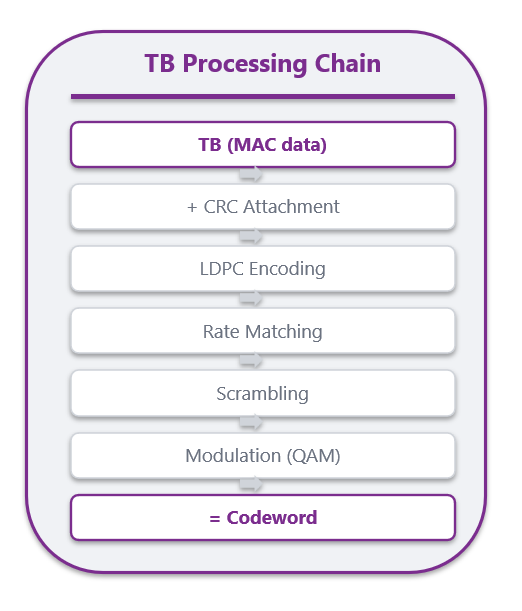
Figure 1.2 Transport Block Processing Chain
What happens to the TB next?
Once the Physical layer receives the TB, it does a series of below operations on it to turn it into Code Words (CW).
- CRC addition — adds a Cyclic Redundacy Checksum so that the UE can detect errors.
- LDPC encoding — adds redundancy so that the UE can fix the errors
- Rate Matching — adjusts the number of coded bits to fit the allocated resources
- Scrambling — XORs with a pseudo random sequence to prevent inter cell interference patters
- Modulation — maps to complex symbols
Finally, after all these steps are applied, a TB becomes a codeword in the physical layer. The full encoding chain is specified in [3GPP TS 38.212][2].
1.2 The Codeword (CW)
A Codeword is the fully encoded and modulated version of a Transport Block. It’s the output of channel coding chain applied to a TB, which is ready to be placed on the reosource grid. In our factory analogy, think of it as the final package with labelling and QR codes attached.
- Each CW has its own MCS. If you have 2 CWs, CW0 might use 64 QAM and CW1 might use 128 QAM.
- For ranks 1 to 4, each TB is associated with 1 CW. For ranks 5 to 8, MAC delivers 2 independent TBs per TTI. Thus, 2 CWs are generated per TTI. Since each TB is associated with a HARQ process, and if CW0 is received fine but CW1 has errors, only CW1 is retransmitted.
Practical tip — when you are looking at traces and see “2 CW”, the rank is 5 or higher.
1.3 Layers and Ranks
Layer and Rank are two concepts that are closely related. Layers represent the actual transmission channels that are generated, while Rank is a property of the channel. A layer represents the number of spatial streams that the gNB chooses to transmit in a given PDSCH. On the other hand, rank represents the capacity of the radio channel to support these layers.
In our factory assembly chain, think of layers as the conveyor belts in operation. Multiple conveyor belts aid in faster delivery. The rank is the total number of conveyor belts in the factory. Some may be in operation, while others maybe not, depending on the load requirement.
Layers ≤ Rank ≤ min(No. of Transmit Ports , No. of Receive Ports)
- Layers ≤ rank: you can’t transmit more independent streams than the channel supports. Pushing 8 layers through a rank-3 channel → streams interfere, decoding fails.
- Layers = rank in the common case: gNB trusts the UE’s Rank Indicator (RI) and schedules that many layers.
- Layers < rank sometimes: scheduler deliberately uses fewer layers for robustness, lower MCS stress, or because higher-priority UEs need spatial resources.
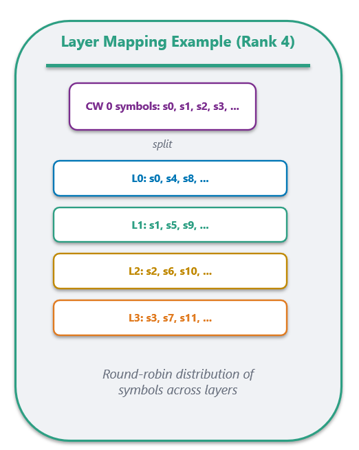
Figure 1.3 Layer Mapping Example
As in Figure 1.3, say your CW 0 has symbols s0, s1, s2, s3, s4 etc., Then with Rank 4, Layer 0 gets s0, s4. Layer 1 gets s1, s5 and so on. Basically it is a round robin distribution.
1.4 Digital Precoding
Precoding takes the layer signals and maps them to logical antenna port signals using matrix multiplication. Think of precoding as routing each conveyor belt to the correct loading dock.
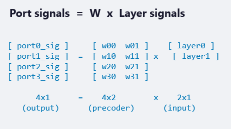
Fig 1.4 Precoding Operation
Figure 1.4 shows how the precoding operation would work on 2 layers transmission. A precoding matrix is applied to the layers to generate signals on logical antenna ports. Thus, every port carries a weighted combination of all layers.
1.4.1 Why Precode?
By choosing the right weights, we can
- Focus energy towards UE location (beamforming gain)
- Create spatial separation between layers so that the UE can untangle them at the receiver
- Null interference towards unintended directions
1.4.2 PMI and the codebook
But how are the weights of the precoding matrix determined? How does the gNB know what W to use? The UE measures the channel and tells it.
Sending the whole precoding matrix over uplink would be too expensive. So the 3GPP defines a code book, which is a predefined set of Weight matrices. The UE just sends the index (Precoding Matrix Indicator (PMI)) as a few bits. Both UE and gNB share the same codebook.
There are two kinds of codebooks in NR:-
- Type 1 codebook — simpler and works well for single-user MIMO. I has around 4 to 8 bits of feedback
- Type 2 codebook- It has higher resolution and is designed for MU-MIMO where precise spatial separation between users matter. It has around 20+ bits of feedback.
The feedback loop is as follows:
-
gNB sends CSI-RS on each logical port
-
UE estimates the channel from CSI-RS
-
UE searches the codebook, finds best W
-
UE reports PMI (plus RI and CQI) back
-
gNB applies that W
5. Logical Antenna Ports
This is the most important concept to understand.
An antenna port is not a physical antenna. It is a logical entity defined by its reference signal.
The formal 3GPP definition (from [TS 38.211, Section 4.4.1][3]) is as follows:
”An antenna port is defined such that the channel over which a symbol on the antenna port is conveyed can be inferred from the channel over which another symbol on the same antenna port is conveyed.”
In plain English, if two symbols experience the same channel, they are on the same antenna port. In our factory analogy, think of Logical Antenna Ports as the labeled loading docks from where packages are shipped. The receiver knows these docks. In another example, think of logical ports as a TV channel. Channel 7 is not a physical cable, but a logical cable. You can receive channel 5 though cable, satellite or internet. The content is the same regardless of the physical delivery method.
There are also scenarios where transmissions with different antenna ports experience the same channel characteristics. In this case, the antenna ports are said to be Quasi Co-Located or QCL
5.1 Why this abstraction matters?
- A gNB with 64 physical antennas might expose only 8 logical ports to the UE.
- The gNB can upgrade from 32 to 64 physical antennas without changing anything to the UE
- Different vendors can implement the physical antenna layout however they want
- The UE only estimates the channel per logical port and not per physical antenna.
5.2 Three reference signals that define ports
- Demodulation Reference Signals (DMRS) — DMRS is transmitted alongside data (PDSCH or PUSCH) and is precoded with the same precoding matrix as the data. i.e., it experiences the same propagation channel.
- Channel State Information Reference Signals (CSI-RS)- CSI-RS is the opposite. They are not precoded. It’s sent per logical port without any precoding applied. So the UE can estimate the raw channel and report PMI, RI or Channel Quality Indicator (CQI).
- Sounding Reference Signals (SRS)-SRS is to the uplink (UL) what CSI-RS is to the downlink (DL) — an unprecoded reference signal on logical ports that lets the receiver see the full channel matrix.
6. Analog Beamforming and Physical Antennas
Here is where we cross from the logical world to the physical world. In our factory analogy, think of these as the actual trucks that deliver data.
- Analog beamforming — Each logical port’s signal is fed to multiple antenna elements, each with a phase shifter. By adjusting the phases, the signals from all elements add up constructively in one direction (towards the UE) and destructively in others. This creates a focused beam
- Hybrid beamforming — In practice, modern gNBs use hybrid beamforming — which is a combination of digital precoding (which handles spatial multiplexing of layers) and analog beamforming (which handles beam steering across many physical elements). This is how Massive MIMO systems work with a manageable number of TRX chains.
- Massivo MIMO example — — 192 physical antenna elements (cross-polarized patches, often organized as 8 columns × 12 rows × 2 polarizations), 64 physical TRX chains (each drives a sub-array), 32 CSI-RS ports (what the UE sees for measurement — typical config), Up to 8 DMRS ports per UE (for data demodulation), Up to 8 layers per UE. So the compression is: 192 elements → 32 ports → 8 layers. Without the port abstraction, the UE would drown trying to estimate 192 channels.
— — — — — — — — — — — — — — — — — — — — — — — — — — — — — — — — -
7. Closing Remarks
This entire chain exists because MIMO is complex, and clean abstractions make it manageable. Without these abstractions, every hardware change would require new UE software, every channel change would break the transmission, and the system couldn’t adapt. These abstractions are the systems intelligence.
— -
If this helped, drop a clap and let me know in the comments what you’d like to see covered next —Bandwidthparts, CSI Type II in detail, and Massive MIMO are on my list.
메타데이터
- post_id
- 07ebdbdd97a2
- slug
- why-do-we-have-antenna-ports-layers-and-rank-arent-they-all-the-same-07ebdbdd97a2
- url
- https://medium.com/@devcult/why-do-we-have-antenna-ports-layers-and-rank-arent-they-all-the-same-07ebdbdd97a2
- canonical_url
- https://medium.com/@devcult/why-do-we-have-antenna-ports-layers-and-rank-arent-they-all-the-same-07ebdbdd97a2
- author_url
- https://medium.com/@devcult
- status
- ok
- fetched_at
- 2026-07-28 06:17:56