Multi‑Qubit Gates: CNOT, CZ, and SWAP Demystified
Build circuits with controlled gates and show their truth tables using the statevector simulator.
Multi‑Qubit Gates: CNOT, CZ, and SWAP Demystified
Build circuits with controlled gates and show their truth tables using the statevector simulator.
Introduction
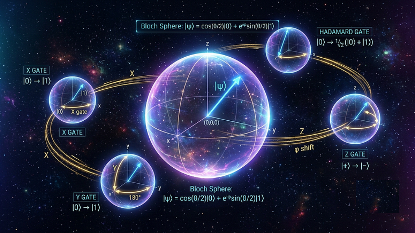
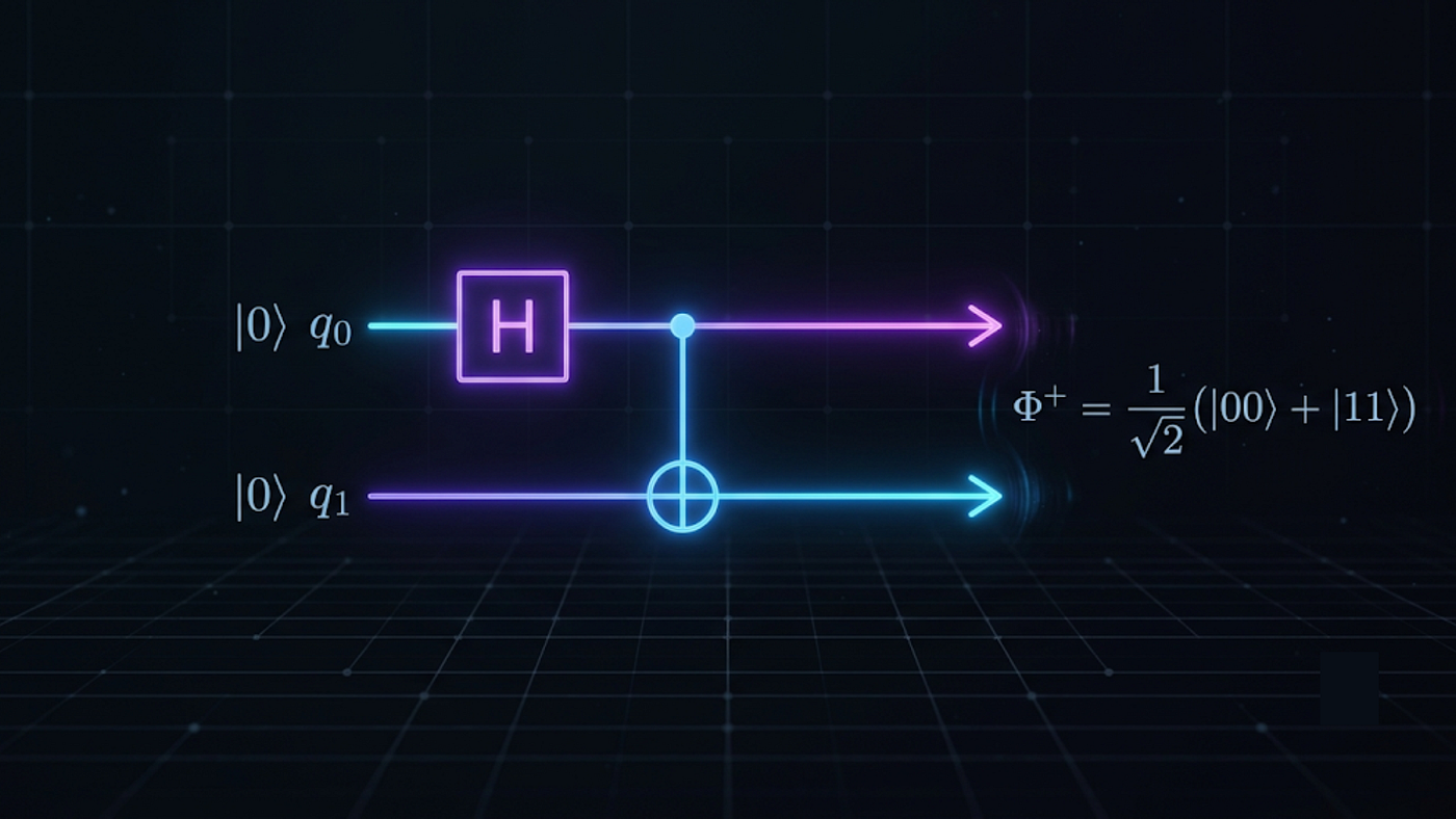
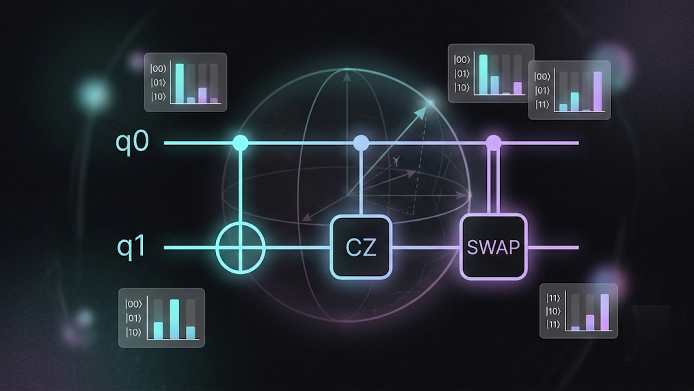
Building on our exploration of single‑qubit gates on the Bloch sphere, we now step into the realm of multi‑qubit gates. These gates are essential for creating entanglement and form the backbone of quantum algorithms such as teleportation, superdense coding, and quantum error correction.
In this article, we’ll demystify three fundamental multi‑qubit gates:
- CNOT (Controlled‑NOT)
- CZ (Controlled‑Z)
- SWAP
We’ll use Qiskit with the Aer simulator to build circuits with these gates and visualise their truth tables using the statevector simulator. The code is designed to run in Jupyter Notebook or Google Colab, making it accessible for both beginners and experienced developers exploring quantum computing.
Setting Up Your Environment
First, set up your Python environment. I recommend using a virtual environment for clean dependency management:
For Windows:
python -m venv medium_quantum_venv
medium_quantum_venv\Scripts\activate
For macOS/Linux:
python3 -m venv medium_quantum_venv
source medium_quantum_venv/bin/activate
Now install the required packages:
pip install qiskit qiskit-aer matplotlib numpyFor the complete notebook with all visualisations, check out the GitHub repository.
Importing Required Libraries
Create a new Jupyter notebook and start with these imports:
from qiskit import QuantumCircuit
from qiskit_aer import AerSimulator
from qiskit.visualization import plot_bloch_multivector
import matplotlib.pyplot as plt
import numpy as np
from IPython.display import display
Helper Function for Visualisation
We’ll create a reusable function to visualise the state vector of any quantum circuit:
def visualize_statevector(circuit, title="Statevector"):
    # Visualize the quantum state as a probability bar chart
    simulator = AerSimulator()
    circuit.save_statevector()
    result = simulator.run(circuit).result()
    statevector = result.get_statevector(circuit)

    # Create bar chart
    n_qubits = circuit.num_qubits
    num_states = 2 ** n_qubits
    states = [format(i, f'0{n_qubits}b') for i in range(num_states)]
    probs = np.abs(statevector) ** 2

    plt.figure(figsize=(14, 6))
    bars = plt.bar(states, probs, color='#1f77b4')
    plt.title(title)
    plt.xlabel('State')
    plt.ylabel('Probability')
    plt.ylim(0, 1)

    # Add value labels on top of bars
    for bar, prob in zip(bars, probs):
        if prob > 0.01:
            plt.text(bar.get_x() + bar.get_width()/2, bar.get_height() + 0.02,
                     f'{prob:.3f}', ha='center', va='bottom')

    plt.show()

    print(f"Statevector: {statevector}")
    return statevector
The CNOT (Controlled‑NOT) Gate
The CNOT gate is a two‑qubit gate that flips the target qubit if the control qubit is in state |1⟩.
Let’s build a circuit to demonstrate the CNOT gate:
# Create a 2-qubit circuit
qc_cnot = QuantumCircuit(2)

# Initialize the state |10⟩ (qubit 0 is control, qubit 1 is target)
# We start with |00⟩, then flip qubit 0 to |1⟩
qc_cnot.x(0)

# Apply CNOT with qubit 0 as control and qubit 1 as target
qc_cnot.cx(0, 1)

# Visualize the statevector
state = visualize_statevector(qc_cnot, "CNOT Gate: |10⟩ → |11⟩")
Expected Output:
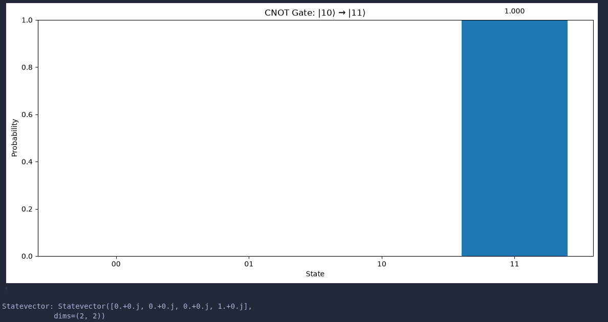
- A bar chart showing probability 1.0 for state |11⟩
- Statevector: [0.+0.j, 0.+0.j, 0.+0.j, 1.+0.j]
Example: CNOT with Control in |0⟩
# Create a 2-qubit circuit
qc_cnot_2 = QuantumCircuit(2)

# Start with |01⟩ (qubit 0 is 0, qubit 1 is 1)
qc_cnot_2.x(1)

# Apply CNOT with qubit 0 as control and qubit 1 as target
qc_cnot_2.cx(0, 1)

# Visualize the statevector
state = visualize_statevector(qc_cnot_2, "CNOT Gate: |01⟩ → |01⟩")
Expected Output:

- A bar chart showing probability 1.0 for state |01⟩
- Statevector: [0.+0.j, 1.+0.j, 0.+0.j, 0.+0.j]
The CZ (Controlled‑Z) Gate
The CZ gate applies a Z gate (phase flip) to the target qubit if the control qubit is in state |1⟩.
# Create a 2-qubit circuit
qc_cz = QuantumCircuit(2)

# Start with |11⟩ (both qubits in |1⟩)
qc_cz.x(0)
qc_cz.x(1)

# Apply CZ gate
qc_cz.cz(0, 1)

# Visualize the statevector
state = visualize_statevector(qc_cz, "CZ Gate: |11⟩ → -|11⟩")
Expected Output:
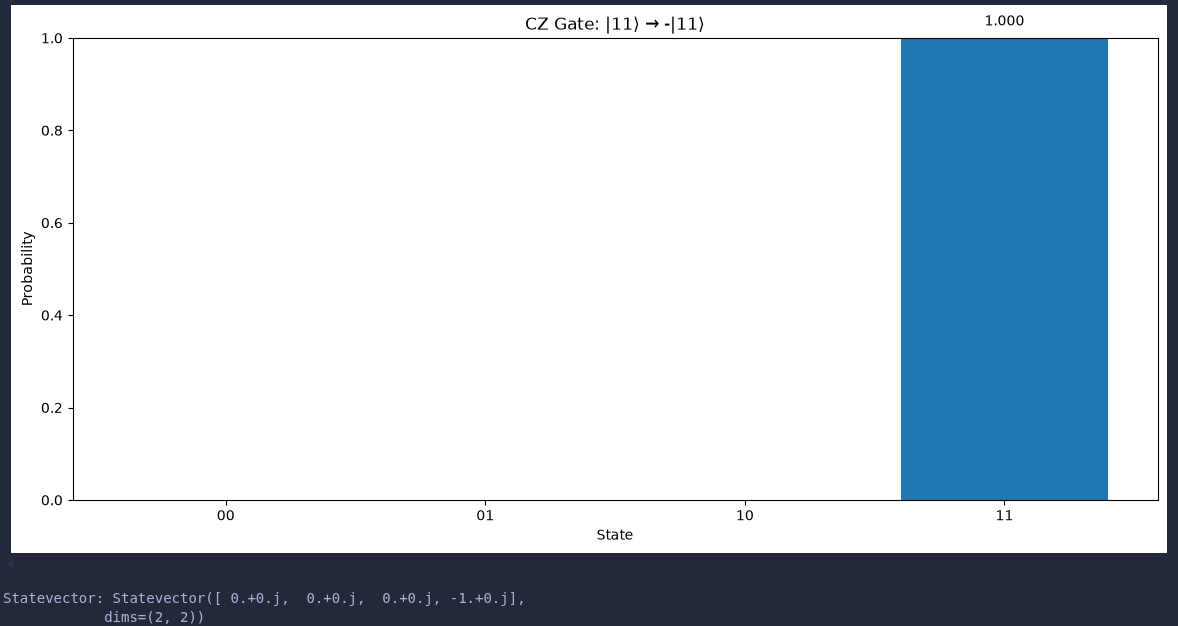
- A bar chart showing probability 1.0 for state |11⟩
- Statevector: [0.+0.j, 0.+0.j, 0.+0.j, -1.+0.j]
Example: CZ with Control in |0⟩
# Create a 2-qubit circuit
qc_cz_2 = QuantumCircuit(2)

# Start with |01⟩ (qubit 0 is 0, qubit 1 is 1)
qc_cz_2.x(1)

# Apply CZ gate
qc_cz_2.cz(0, 1)

# Visualize the statevector
state = visualize_statevector(qc_cz_2, "CZ Gate: |01⟩ → |01⟩")
Expected Output:

- A bar chart showing probability 1.0 for state |01⟩
- Statevector: [0.+0.j, 1.+0.j, 0.+0.j, 0.+0.j]
The SWAP Gate
The SWAP gate exchanges the states of two qubits.
# Create a 2-qubit circuit
qc_swap = QuantumCircuit(2)

# Start with |10⟩
qc_swap.x(0)

# Apply SWAP gate
qc_swap.swap(0, 1)

# Visualize the statevector
state = visualize_statevector(qc_swap, "SWAP Gate: |10⟩ → |01⟩")
Expected Output:

- A bar chart showing probability 1.0 for state |01⟩
- Statevector: [0.+0.j, 0.+0.j, 1.+0.j, 0.+0.j]
Example: SWAP with |01⟩
# Create a 2-qubit circuit
qc_swap_2 = QuantumCircuit(2)

# Start with |01⟩
qc_swap_2.x(1)

# Apply SWAP gate
qc_swap_2.swap(0, 1)

# Visualize the statevector
state = visualize_statevector(qc_swap_2, "SWAP Gate: |01⟩ → |10⟩")
Expected Output:

- A bar chart showing probability 1.0 for state |10⟩
- Statevector: [0.+0.j, 0.+0.j, 1.+0.j, 0.+0.j]
Visualising All Gates Together
Let’s display all gate effects in one figure for comparison:
# Define base circuits
gates = [
    ("CNOT: |10⟩ → |11⟩", QuantumCircuit(2)),
    ("CZ: |11⟩ → -|11⟩", QuantumCircuit(2)),
    ("SWAP: |10⟩ → |01⟩", QuantumCircuit(2)),
]

# Apply operations
# CNOT
gates[0][1].x(0)
gates[0][1].cx(0, 1)

# CZ
gates[1][1].x(0)
gates[1][1].x(1)
gates[1][1].cz(0, 1)

# SWAP
gates[2][1].x(0)
gates[2][1].swap(0, 1)

# Initialize simulator
simulator = AerSimulator()

# Simulate and display each statevector
for label, circuit in gates:
    circ_copy = circuit.copy()
    circ_copy.save_statevector()

    result = simulator.run(circ_copy).result()
    statevector = result.get_statevector(circ_copy)

    # Create bar chart
    n_qubits = circ_copy.num_qubits
    num_states = 2 ** n_qubits
    states = [format(i, f'0{n_qubits}b') for i in range(num_states)]
    probs = np.abs(statevector) ** 2

    plt.figure(figsize=(14, 6))
    bars = plt.bar(states, probs, color='#1f77b4')
    plt.title(label)
    plt.xlabel('State')
    plt.ylabel('Probability')
    plt.ylim(0, 1)

    for bar, prob in zip(bars, probs):
        if prob > 0.01:
            plt.text(bar.get_x() + bar.get_width()/2, bar.get_height() + 0.02,
                     f'{prob:.3f}', ha='center', va='bottom')

    plt.show()
    print(f"Statevector: {statevector}\n")
Expected Output:

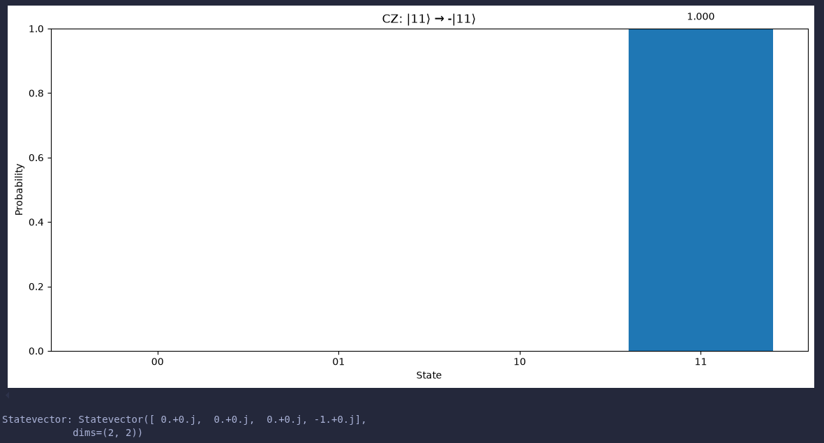
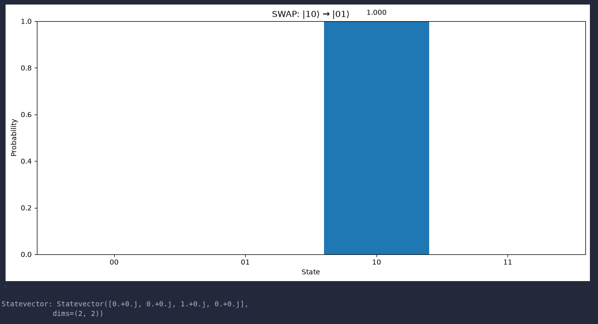
- Three bar charts showing the results of CNOT, CZ, and SWAP gates
- Each chart clearly shows the resulting state after applying the gate
- The CZ gate shows a negative phase on the |11⟩ component
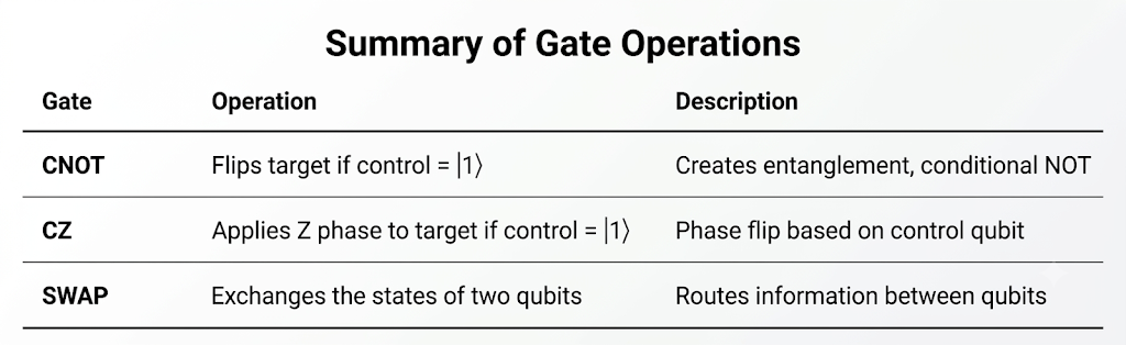
Summary of Gate Operations
Conclusion
Multi‑qubit gates are essential for creating entanglement and building powerful quantum algorithms. In this article, we explored three fundamental gates:
- CNOT is the workhorse of quantum computing, creating entanglement and enabling conditional operations.
- CZ applies a phase flip based on the control qubit’s state, which is useful in many quantum algorithms.
- SWAP exchanges qubit states, which is crucial for routing information in quantum circuits.
By visualising the state vectors as probability distributions, we can clearly see how these gates transform qubit states and intuitively understand their truth tables.
The complete code is available in the GitHub repository linked above. Feel free to experiment by modifying the initial states or applying sequences of gates to see how the state vectors change!
메타데이터
- post_id
- 08ac2882e543
- slug
- multi-qubit-gates-cnot-cz-and-swap-demystified-08ac2882e543
- url
- https://medium.com/@rahul.techarticles/multi-qubit-gates-cnot-cz-and-swap-demystified-08ac2882e543
- canonical_url
- https://medium.com/@rahul.techarticles/multi-qubit-gates-cnot-cz-and-swap-demystified-08ac2882e543
- author_url
- https://medium.com/@rahul.techarticles
- status
- ok
- fetched_at
- 2026-08-03 11:07:46