Extracting and Writing Firmware to the CAT28C16 EEPROM
Inspired by Halt and Catch Fire
When Chips Still Had Souls
Extracting and Writing Firmware to the CAT28C16 EEPROM
Inspired by Halt and Catch Fire
While watching the TV series Halt and Catch Fire, I got fascinated by the scene where they dump firmware from a chip. That scene led me down a rabbit hole of research, where I discovered Ben Eater’s amazing guide on working with EEPROMs. Naturally, I had to try it myself.
I decided to work with the CAT28C16AP, an old-school 2K x 8 EEPROM. Here’s how I wired everything up and what I learned from the process.
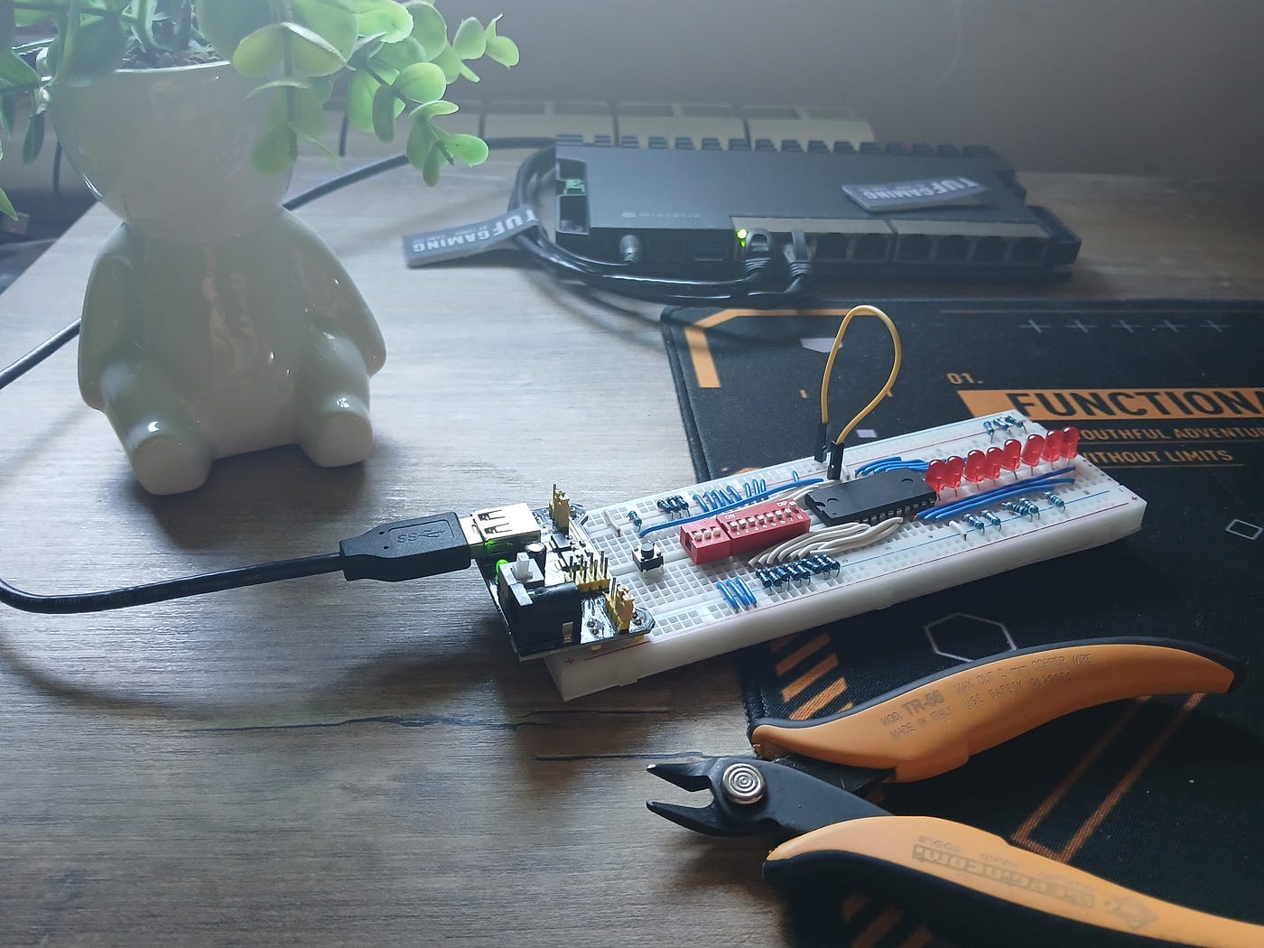
Photo by Im0nk3yar0und
How It Works
To read or write data from this chip, we have to control its address pins, manage data lines, and toggle a few control pins like CE(Chip Enable), OE(Output Enable), and WE(Write Enable).
Parts Used:
- CAT28C16AP EEPROM
- DIP switches (DIP8 + DIP3 for address lines)
- LEDs for visual output
- 330Ω, 10kΩ
- Push button
- 5V power supply
- Breadboard and jumper wires
- Write pulse: 1nF capacitor, 10kΩ and 680Ω resistors
In Ben Eater’s YouTube guide, he uses a classic RC (resistor-capacitor) circuit to generate a short LOW pulse on the WE (Write Enable) pin of the EEPROM. This pulse needs to fall within the range of 100 to 1000 nanoseconds to be recognized as a valid write operation by the chip.

How does this work?
The capacitor charges and discharges through the resistors when a button is pressed. This creates a brief voltage drop — essentially a clean and controlled LOW signal — on the WE pin. During this moment:
- CE (Chip Enable) must be LOW (always enabled)
- OE (Output Enable) must be HIGH (disabled)
- WE receives the short LOW pulse that triggers the write
This setup ensures that the timing is consistent and reliable, especially when manually triggering a write with a push button.
My Setup (Minimalist Approach):
In my case, I was able to perform writes without using the capacitor. I only used a 10Ω resistor in line with the push button connected to the WE pin.
Even without a dedicated RC circuit, there are parasitic capacitances in the breadboard wiring and the chip itself. These small inherent delays, combined with the physical “bounce” of a mechanical push button, are often enough to create a brief, naturally-occurring LOW pulse. It may not be as clean or predictable as the RC method, but it can still fall within the required 100–1000ns range needed to write data successfully.
Key Connections Explained
Pin Setup
Power & Enable Pins:
- Pin 24 (Vcc) → 5V
- Pin 12 (GND) → GND
- Pin 18 (CE — Chip Enable) → GND (Always LOW to enable the chip)
- **Pin 20 (OE — Output Enable), **LOW during read operations (enables output on data pins), HIGH during write operations (disables output)
- Pin 21 (WE — Write Enable), HIGH during normal operation, Pulled LOW briefly (100–1000 ns pulse) to perform a write

Address Lines:
We use a combination of an 8-switch DIP (for A0–A7) and a 3-switch DIP (for A8–A10).
- A0-A7 (pins 1–8) to an 8-position DIP switch
- A8-A10 (pins 23,22,19) to a 3-position DIP switch
- Each switch leg has a 10kΩ pull-down resistor when OFF
This setup allows us to easily set the address we want to read or write.
   DIP8 Switch       DIP3 Switch
  +------------+    +------------+
  | A0 - Pin 8 |    | A8 - Pin23 |
  | A1 - Pin 7 |    | A9 - Pin22 |
  | A2 - Pin 6 |    |A10 - Pin19 |
  | ...        |    +------------+
  | A7 - Pin 1 |
  +------------+
  OFF → 10kΩ to GND
  ON  → 5V
Photo by Im0nk3yar0und
Data Lines
These are bidirectional pins used for both reading and writing.
- I/O0-I/O7 (pins 9–11,13–17) to LEDs with 330Ω current-limiting resistors
- OE (pin 20) → LOW (output enable)
- OE (pin 20) → HIGH (output disable)
  +----------------------------------------------+
  |                Data Lines                    |
  +------------+-----------+---------------------+
  | Pin Number | I/O       | Connection          |
  +------------+-----------+---------------------+
  | 9          | I/O0      | LED → 330Ω → GND    |
  | 10         | I/O1      | LED → 330Ω → GND    |
  | 11         | I/O2      | LED → 330Ω → GND    |
  | 13         | I/O3      | LED → 330Ω → GND    |
  | 14         | I/O4      | LED → 330Ω → GND    |
  | 15         | I/O5      | LED → 330Ω → GND    |
  | 16         | I/O6      | LED → 330Ω → GND    |
  | 17         | I/O7      | LED → 330Ω → GND    |
  +------------+-----------+---------------------+
We use LEDs to visually inspect the output data during reads.
When writing, we manually set the desired data bits HIGH by connecting those I/O pins to 5V.
⚠️ The chip doesn’t limit current, so resistors are mandatory when using LEDs.
Reading the Chip
To read data:
- Set address using DIP switches
- CE is already low (enabled)
- OE is pulled low (output enable)
- The selected byte appears on I/O lines, lighting the LEDs
Writing to the Chip
To write data to the chip:
- Set OE (Pin 20) HIGH to disable output mode.
- Connect the data lines (I/O pins) to 5V for bits you want to write as
1. - Pulse WE (Pin 21) LOW for 100ns–1000ns to trigger the write.

Photo by Im0nk3yar0und
Conclusion
There’s something magical about seeing data represented physically through blinking LEDs that makes all the abstract concepts concrete.
This project was a fun mix of retro tech, electronics, and a bit of TV inspiration. Reading and writing data to an old EEPROM with just DIP switches and LEDs is both educational and surprisingly satisfying. Big thanks to Halt and Catch Fire and Ben Eater for sparking the idea!
메타데이터
- post_id
- 11bd7e6dca7c
- slug
- extracting-and-writing-firmware-to-the-cat28c16-eeprom-11bd7e6dca7c
- url
- https://medium.com/@im0nk3yar0und/extracting-and-writing-firmware-to-the-cat28c16-eeprom-11bd7e6dca7c
- canonical_url
- https://medium.com/@im0nk3yar0und/extracting-and-writing-firmware-to-the-cat28c16-eeprom-11bd7e6dca7c
- author_url
- https://medium.com/@im0nk3yar0und
- status
- ok
- fetched_at
- 2026-07-20 08:23:55