PROJECT PREPARATION OF INTERVIEW IN THE DOMAIN OF POWER ELECTRONICS……
PV-MPPT Based Grid-Connected Energy Storage System with Real-Time HIL Validation
PROJECT PREPARATION OF INTERVIEW IN THE DOMAIN OF POWER ELECTRONICS……
PV-MPPT Based Grid-Connected Energy Storage System with Real-Time HIL Validation
Project Overview
This project focused on designing and validating a grid-connected photovoltaic (PV) power generation system integrated with battery energy storage. The objective was to maximize solar power extraction, manage energy flow between the PV array, battery, and grid, and ensure stable operation under varying environmental and load conditions.
The complete system was developed in MATLAB/Simulink and later deployed on Opal-RT for Hardware-in-the-Loop (HIL) real-time testing.
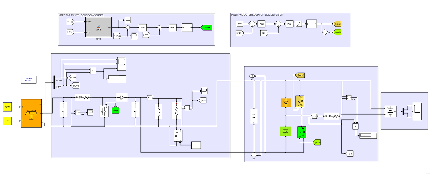
fig:1 PV — BOOST CONVERTER — LOAD — DC-LINK — BIDIRECTIONAL CONVERTER — BATTERY — MPPT CONTROL
1. System Architecture
The system consisted of four major subsystems:
A. Photovoltaic (PV) Array
- Generates DC power from solar irradiance.
- Output voltage and current vary with sunlight and temperature.
- Since PV characteristics are nonlinear, maximum available power must be continuously tracked.
B. MPPT Controller
- Implemented a Maximum Power Point Tracking (MPPT) algorithm.
- Continuously adjusts the operating point of the PV array to extract maximum power.
- The MPPT controller generates duty cycle commands for the DC-DC converter.
C. Bidirectional DC-DC Converter
- Connected between the battery and DC bus.
- Operates in two modes:
Charging Mode
When PV generation exceeds load demand:
- Excess energy charges the battery.
Discharging Mode
When PV generation is insufficient:
- Battery supplies power to maintain DC bus stability.
This enables effective energy management and improves system reliability.

fig:2 connected with grid through voltage source inverter — pll — dq transformation
D. Grid-Connected Voltage Source Converter (VSC)
- Connects the DC bus to the AC grid.
- Converts DC power into synchronized AC power.
- Controls active and reactive power exchange with the utility grid.
2. Control Strategy
The major control challenge was maintaining stable power transfer while synchronizing with the grid.
Phase Locked Loop (PLL)
First, a PLL was implemented to:
- Track grid voltage angle.
- Generate synchronous reference frame information.
This angle is used for d-q transformation.
3. d-q Reference Frame Control
Instead of controlling three-phase AC quantities directly, the system uses the Park (d-q) transformation.
The three-phase variables:
V_a, V_b, V_c.
are transformed into:
V_d, V_q
in a rotating reference frame synchronized with the grid.
Benefits
- AC signals become DC quantities.
- Easier controller design.
- Independent control of active and reactive power.
Power Control Logic
d-axis Current (Id)
Controls Active Power (P)
P∝I_d
Increasing Id: More real power injected into grid.
q-axis Current (Iq)
Controls Reactive Power (Q)
Q∝I_q
Adjusting Iq:
- Controls power factor.
- Supports grid voltage regulation.
Thus active and reactive power are decoupled and controlled independently.
4. Converter Controller Design
To ensure stable operation:
Mathematical Modeling
I derived the dynamic equations of:
- DC bus
- Filter inductors
- Converter currents
- Grid interface
Then developed a state-space model of the system.
System Linearization
Since the converter system is nonlinear:
- Selected an operating point.
- Linearized the model around that point.
This produced a small-signal model suitable for control design.
The linearized model helped analyze:
- Stability
- Pole locations
- Dynamic response
5. PID Controller Tuning
Using the linearized model:
Current Control Loop
Designed PID controllers for:
- d-axis current loop
- q-axis current loop
DC Bus Voltage Control Loop
Another PID controller was designed to:
- Maintain constant DC-link voltage.
- Balance power flow between PV, battery, and grid.
The tuning process focused on:
- Fast settling time
- Minimal overshoot
- Robustness against irradiance variations and load disturbances
6. MATLAB/Simulink Simulation
The entire system was simulated in MATLAB/Simulink.
Various operating scenarios were tested:
Scenario 1
High irradiance:
- PV supplies load.
- Excess power charges battery.
Scenario 2
Low irradiance:
- Battery discharges.
- Supports load demand.
Scenario 3
Grid power export:
- Excess solar energy injected into grid.
Scenario 4
Load disturbance:
- Controllers maintain DC bus stability.
Performance metrics evaluated:
- DC bus voltage regulation
- Grid current quality
- Active/reactive power control
- Battery charging/discharging behavior
7. Real-Time HIL Implementation Using Opal-RT
After simulation validation:
The model was deployed on an Opal-RT real-time simulator.
Why HIL?
Traditional simulation:
- Runs offline.
HIL simulation:
- Executes in real time.
- Mimics actual hardware behavior.
This allows verification of:
- Controller performance
- Timing constraints
- Real-world dynamic responses
before implementing on physical hardware.
Results Achieved
- Successful maximum power extraction using MPPT.
- Stable DC-link voltage regulation.
- Smooth battery charge/discharge transitions.
- Independent active and reactive power control through d-q control.
- Stable grid synchronization using PLL.
- Real-time validation on Opal-RT confirming controller effectiveness.
“I developed a grid-connected PV system integrated with battery energy storage. The system consisted of a PV array, MPPT controller, bidirectional DC-DC converter, battery, and a grid-connected VSC. The MPPT algorithm maximized solar power extraction, while the bidirectional converter managed battery charging and discharging based on power availability. For grid interfacing, I implemented a PLL-based d-q reference frame control strategy, where the d-axis current controlled active power and the q-axis current controlled reactive power. I derived the system dynamics, linearized the model around an operating point, and tuned PID controllers for DC-link voltage and current regulation to ensure stable power flow. The complete system was simulated in MATLAB/Simulink and then deployed on Opal-RT for real-time Hardware-in-the-Loop testing, where I validated controller performance under different irradiance and load conditions”.
INTERVIEW QUESTION AS CROSS-QUESTIONS:
Questions Related to d-q Control
1. Why do we use d-q transformation instead of controlling three-phase currents directly?
Expected Answer: The d-q transformation converts sinusoidal AC quantities into DC quantities in a rotating reference frame synchronized with the grid. This simplifies controller design because PID controllers can regulate DC signals more effectively than sinusoidal signals.
2. What is the role of the Phase-Locked Loop (PLL)?
Expected Answer: The PLL tracks the grid voltage angle and frequency. This angle is required for Park’s Transformation to convert three-phase quantities into the synchronous d-q reference frame.
3. Why is the d-axis aligned with the grid voltage vector?
Expected Answer: Aligning the d-axis with the grid voltage makes the q-axis voltage approximately zero (Vq≈0V_q \approx 0Vq≈0). This simplifies power equations and allows independent control of active and reactive power.
4. How does IdI_dId control active power?
Expected Answer: When the d-axis is aligned with the grid voltage:
P=32VdIdP=\frac{3}{2}V_dI_dP=23VdId
Since VdV_dVd is nearly constant, active power is directly proportional to IdI_dId. Increasing IdI_dId increases real power injection into the grid.
5. How does IqI_qIq control reactive power?
Expected Answer: Under voltage-oriented control:
Q=−32VdIqQ=-\frac{3}{2}V_dI_qQ=−23VdIq
Reactive power is directly controlled by IqI_qIq. By changing IqI_qIq, the converter can inject or absorb reactive power.
6. What happens if Iq=0I_q = 0Iq=0?
Expected Answer: The converter operates at unity power factor because no reactive power is exchanged with the grid.
7. What happens if the PLL loses synchronization?
Expected Answer: The d-q transformation becomes inaccurate, causing incorrect active and reactive power control. This can lead to oscillations, poor power quality, and possible converter instability.
Questions Related to the VSC
8. Why is a Voltage Source Converter used?
Expected Answer: The VSC converts DC power from the PV and battery system into AC power synchronized with the grid while controlling active and reactive power flow.
9. What is the purpose of the DC-link capacitor?
Expected Answer: The DC-link capacitor acts as an energy buffer between the DC and AC sides. It helps maintain a stable DC bus voltage during power fluctuations.
10. Why must the DC-link voltage remain constant?
Expected Answer: A stable DC-link voltage ensures proper converter operation and accurate power transfer between the DC and AC sides.
Questions Related to System Modeling and Linearization
11. Why did you linearize the system?
Expected Answer: The converter system is nonlinear. Linearization around an operating point allows us to develop a small-signal model for stability analysis and controller design.
12. What is an operating point?
Expected Answer: An operating point is the steady-state condition around which the nonlinear system is approximated as linear.
13. Why can’t we directly tune PID controllers on the nonlinear model?
Expected Answer: Nonlinear systems are difficult to analyze mathematically. Linearization enables the use of classical control techniques such as root locus, Bode plots, and pole-zero analysis.
14. What parameters did you consider while tuning PID controllers?
Expected Answer:
- Settling time
- Rise time
- Overshoot
- Steady-state error
- Stability margins
Questions Related to the Bidirectional Converter
15. Why is the converter bidirectional?
Expected Answer: Because power must flow in both directions:
- Battery charging when PV generation exceeds demand.
- Battery discharging when PV generation is insufficient.
16. How does the converter decide whether to charge or discharge the battery?
Expected Answer: The decision is based on the power balance between PV generation, load demand, battery state, and grid requirements.
17. What control objective does the battery serve?
Expected Answer: The battery helps maintain DC bus stability and ensures uninterrupted power supply during solar power fluctuations.
Questions Related to MPPT
18. Why is MPPT necessary?
Expected Answer: PV output varies with irradiance and temperature. MPPT continuously adjusts the operating point to extract maximum available power.
19. Which MPPT algorithm did you use?
Possible Answer (if Perturb & Observe): I used the Perturb and Observe (P&O) algorithm because of its simplicity and ease of implementation.
Then be prepared for:
Follow-up: “What are the disadvantages of P&O?”
Answer:
- Oscillates around MPP.
- Slower under rapidly changing irradiance.
Questions Related to HIL (Opal-RT)
20. Why did you use Opal-RT?
Expected Answer: Opal-RT allows real-time Hardware-in-the-Loop testing, enabling controller validation under realistic operating conditions before deploying to physical hardware.
21. What is the difference between Simulink simulation and HIL testing?
SimulinkHILOffline executionReal-time executionIdeal environmentHardware-like environmentNo timing constraintsActual timing constraintsPure software testingController validation
22. What challenges did you face during HIL implementation?
Good answers:
- Solver time-step selection
- Synchronization issues
- Signal scaling
- Real-time computational constraints
High-Probability Final Interview Question
“Explain the complete power flow in your system.”
Model Answer:
Solar power is generated by the PV array and tracked using an MPPT controller to extract maximum power. The generated power is delivered to the DC bus through a converter. A bidirectional DC-DC converter manages battery charging and discharging depending on power availability. The DC-link voltage is maintained through a voltage control loop. A grid-connected VSC converts DC power into synchronized AC power and injects it into the grid. Using PLL-based d-q control, the d-axis current regulates active power while the q-axis current regulates reactive power. The complete system was modeled in MATLAB/Simulink, linearized for controller design, PID controllers were tuned for stability, and the final system was validated in real time using Opal-RT HIL testing.
Advanced Cross-Questions on Your PV–Battery–Grid Project
MPPT Section
Q1. Why can’t we connect the PV panel directly to the DC bus?
Answer: The PV operating voltage changes with irradiance and temperature. If connected directly, the panel may not operate at its Maximum Power Point (MPP), resulting in lower power extraction. The DC-DC converter adjusts the operating point to continuously track the MPP.
Q2. What happens if MPPT is disabled?
Answer: The PV array operates at a non-optimal voltage and current point, causing significant power loss. The system may extract only 60–80% of available solar power depending on conditions.
Q3. Why does the PV curve have only one MPP under uniform irradiance?
Answer: The nonlinear I-V characteristics create a unique point where the product V×IV \times IV×I is maximum.
Q4. What happens to the MPP when irradiance increases?
Answer: Current increases significantly while voltage changes only slightly, causing the maximum power point to shift upward.
Bidirectional Converter
Q5. Why not use two separate converters instead of one bidirectional converter?
Answer: A bidirectional converter reduces component count, cost, losses, and control complexity while allowing power flow in both directions.
Q6. What determines whether the converter operates in buck or boost mode?
Answer:
- Charging battery → Buck mode
- Discharging battery → Boost mode
depending on the voltage levels of the battery and DC bus.
Q7. If the battery voltage drops significantly, what happens?
Answer: The converter increases duty ratio during boost operation to maintain DC bus voltage. However, excessive discharge may trigger battery protection limits.
DC Link Questions
Q8. Why is the DC-link capacitor important?
Answer: It acts as an energy buffer between DC and AC stages and reduces voltage ripple caused by power fluctuations.
Q9. How do you select the DC-link capacitor value?
Answer: Based on:
- Allowable voltage ripple
- Power rating
- Switching frequency
- Transient response requirements
Q10. What happens if the DC-link capacitor is too small?
Answer:
- Large voltage ripple
- Poor dynamic response
- Increased converter stress
- Possible instability
d-q Control Questions
Q11. Why is d-q control preferred over abc control?
Answer: Because sinusoidal AC variables become DC quantities in the rotating frame, making control simpler and improving dynamic performance.


PLL Questions
Q16. Why is PLL needed?
Answer: To continuously estimate grid phase angle and frequency for synchronization.
Q17. What happens if PLL bandwidth is very high?
Answer: It reacts quickly but becomes sensitive to noise and harmonics.
Q18. What happens if PLL bandwidth is very low?
Answer: Slower synchronization and poor response to frequency changes.
Current Controller Questions
Q19. Why use an inner current loop and outer voltage loop?
Answer: Current dynamics are much faster than voltage dynamics. Cascaded control improves stability and transient response.
Q20. Which loop should be faster?
Answer: The inner current loop.
Typically:
- Current loop bandwidth = 500–1000 Hz
- Voltage loop bandwidth = 50–100 Hz
Q21. What happens if voltage loop becomes faster than current loop?
Answer: The cascaded control assumption breaks down, leading to oscillations and instability.
Linearization Questions
Q22. What exactly is system linearization?
Answer: Approximating a nonlinear system around a steady-state operating point using first-order Taylor expansion.
Q23. Why is linearization valid only near the operating point?
Answer: Because higher-order nonlinear terms are neglected.
Q24. What information do poles provide?
Answer:
- Stability
- Damping
- Oscillation frequency
- Settling time
Q25. What happens if a pole moves to the right-half plane?
Answer: The system becomes unstable.
PID Controller Questions
Q26. Why not use only a PI controller?
Answer: PI is often sufficient for current control. Derivative action improves transient response but can amplify measurement noise.
Q27. What is integrator windup?
Answer: When the integral term accumulates excessively during actuator saturation, causing overshoot and slow recovery.
Q28. How can anti-windup be implemented?
Answer:
- Integrator clamping
- Back-calculation
- Conditional integration
Grid Integration Questions
Q29. What happens if grid voltage suddenly dips?
Answer: The converter must ride through the fault, limit current, and maintain stability according to grid code requirements.
Q30. What is Low Voltage Ride Through (LVRT)?
Answer: The ability of a converter to remain connected during temporary voltage sags.
Q31. Why inject reactive power during a voltage sag?
Answer: Reactive power supports grid voltage recovery.
HIL Questions
Q32. Why perform HIL if simulation already works?
Answer: Simulation does not capture real-time execution constraints. HIL verifies controller behavior under realistic timing conditions.
Q33. What is a real-time step?
Answer: The simulation must complete all calculations within a fixed interval (e.g., 50 µs).
Q34. What happens if execution time exceeds the real-time step?
Answer: A real-time overrun occurs, invalidating results.
Expert-Level Questions
Q35. If the battery is removed, can the system still work?
Answer: Yes, but power fluctuations from PV directly affect the DC bus and grid power injection. The battery improves stability and energy balancing.
Q36. Why use a VSC instead of a Current Source Converter (CSC)?
Answer: VSCs offer:
- Better controllability
- Faster dynamics
- Easier PWM implementation
- Lower component size
Q37. What are the major losses in your system?
Answer:
- Switching losses
- Conduction losses
- Filter losses
- Battery losses
- Transformer losses (if present)
Q38. If switching frequency doubles, what happens?
Answer: Advantages:
- Lower current ripple
- Smaller filter size
Disadvantages:
- Higher switching losses
- Increased thermal stress
Q39. What would you improve if given more time?
Strong Answer:
I would replace the conventional PID-based control with Model Predictive Control (MPC) or adaptive control techniques, incorporate advanced MPPT methods under partial shading conditions, and perform grid fault ride-through analysis according to modern grid codes.
Q40. What is the biggest technical challenge in this project?
Strong Answer:
The biggest challenge was coordinating multiple control loops — MPPT, battery management, DC-link regulation, and grid synchronization — while maintaining stability under varying irradiance and load conditions. Proper controller tuning and system linearization were critical to achieving stable operation.
메타데이터
- post_id
- 12d3b2a6b5b2
- slug
- project-preparation-of-interview-in-the-domain-of-power-electronics-12d3b2a6b5b2
- url
- https://medium.com/@brokenversion11/project-preparation-of-interview-in-the-domain-of-power-electronics-12d3b2a6b5b2
- canonical_url
- https://medium.com/@brokenversion11/project-preparation-of-interview-in-the-domain-of-power-electronics-12d3b2a6b5b2
- author_url
- https://medium.com/@brokenversion11
- status
- ok
- fetched_at
- 2026-06-09 15:37:30