How to connect a TFT display (SPI interface) and a BME280 sensor (I2C interface) to a Heltec…
The Heltec Wireless Stick Lite V3 is a tiny, ESP32-S3-driven development board with an SX1262 LoRa module. As many people are claiming…
How to connect a TFT display (SPI interface) and a BME280 sensor (I2C interface) to a Heltec Wireless Stick Lite V3
The **Heltec Wireless Stick Lite V3 is a tiny, ESP32-S3-driven development board with an SX1262 LoRa module. As many people are claiming about using external devices like sensors or displays using an I2C or SPI** interface, I wrote this tutorial to help you in finding solutions.
Note: this tutorial is about the Heltec Wireless Stick Lite V3 and not the Heltec Wireless Stick V3, but for the other variant I wrote a similar tutorial (**How to connect a TFT display (SPI interface) and a BME280 sensor (I2C interface) to a Heltec Wireless Stick V3**).
These are the topics of this tutorial:
- Profile of the Heltec Wireless Stick Lite V3 board
- Pinout of the board
- Overview of the development environment and the sketch
- Using an I2C sensor like a BME280 environment sensor
- Using an SPI device like a TFT display (ST7789 chip)
- Other settings
- Summary
Profile of the Heltec Wireless Stick Lite V3 board
The Heltec Wireless Stick Lite (V3) is an ESP32-S3 + SX1262 LoRa Node and is Meshtastic and LoRaWAN compatible. It is driven by an ESP32-S3FN8 processor with 8 MB flash memory (no PSRAM memory). The LoRa module is an SX1262 type, and the USB-to-UART bridge is done by a CP2102 chip.
The board is exposing 7 ADC1 + 2 ADC2 GPIOs (in total 2 * 17 breadboard pins). For Li-Ion powering, an SH1.25–2 connector is available with an integrated lithium battery management system (charge and discharge management, overcharge protection, battery power detection, USB / battery power automatic switching) with status LED (orange).
On the board, there are two buttons (Reset and Boot) available plus a white LED for user purposes.
To save electricity during desired sleep phases, a switchable 3.3-volt output is available.
Pinout of the board
The pinout of the board is taken from the Heltec product page, so all credits go to them:
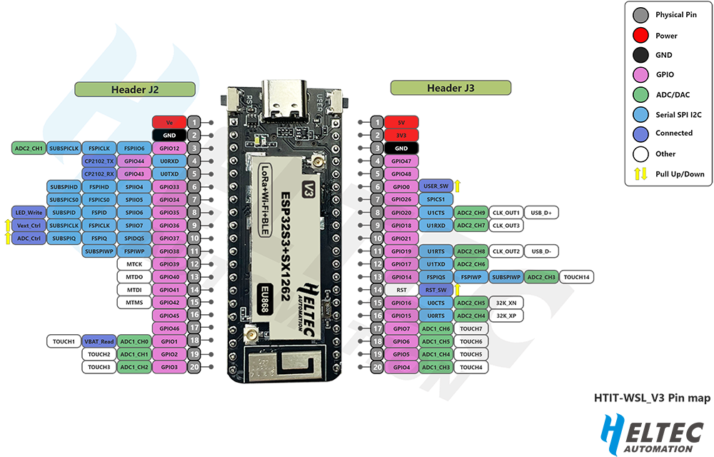
Please note: although the “sister” variant of this device, the Heltec Wireless Stick V3, is looking very equal, there is a different pinout for that device!
Overview of the development environment and the sketch
As a general note, I’m using the regular [Android ESP32 boards](https://github.com/espressif/arduino-esp32) for developing my LoRa applications. I already know that Heltec is providing its own framework, but as I own different LoRa devices, I do not want to write different codes for my devices. The sample code is written on Arduino 2.3.6 (Windows) and ESP32 boards version 3.3.4, which is based on Espressif’s IDE 5.5.1.
The sketch is pre-configured for the Heltec Wireless Stick Lite V3 and uses its own settings file (Heltec_Wireless_Stick_Lite_V3_Hardware_Settings.h) for the pin assignments.
Although the board is primarily intended for LoRa applications, the sketch does not use any LoRa functions.
The sketch uses these interfaces and displays these values:
- The white onboard LED is blinking twice after the sketch has started, once after a Boot button press, and is blinking long when the connection to the BME280 sensor fails
- A BME280 environmental sensor is connected to the board via the I2C interface and measures the temperature, humidity, and air pressure
- The program reads the ESP32-S3 internal chip temperature
- The Boot button is read via interrupt control, and pressing the button results in an update of the values and the lighting of the onboard LED
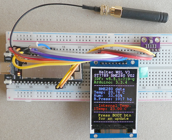
- A TFT display, powered by an ST7789 chip, is connected to the board. The following data is displayed on the 240x320 pixel display:
- the short device name (“WS V3”) and sketch version number
- the Arduino ESP32 board version and underlying Espressif library version
- Environmental data from the BME280 sensor (temperature in degrees Celsius, humidity, and barometric air pressure)
- Internal temperature of the ESP32-S3 chip
- A note on updating the data after a Boot button press
Using an I2C sensor like a BME280 environment sensor
I’m using the **Adafruit BME280 library** version 2.2.4 for this task. I am using the Wire library to set up an individual pin setting for connecting the sensor (the sketch is using the “not defined” (longer) path):
// init BME280 sensor
#ifdef IS_BME280
#ifndef IS_SECOND_I2C_BUS
  bool bme_status = bme.begin(BME280_I2C_ADDRESS);  // address either 0x76 or 0x77
  Serial.printf("Init BME280 on System I2C pins SDA: %d SCL: %d\n", SDA, SCL);
#else
  bool wireStatus = Wire1.begin(BME280_I2C_SDA_PIN, BME280_I2C_SCL_PIN);
  Serial.printf("Init Wire1/BME280 on Second I2C pins SDA: %d SCL: %d\n", BME280_I2C_SDA_PIN, BME280_I2C_SCL_PIN);
  if (!wireStatus) {
    Serial.println(F("Wire1 failed to init"));
    display3 = "Wire FAILURE";
    display4 = "System is halting";
    displayData();
    while (1)
      ;
  } else {
    display3 = "BME280/Wire1 ACTIVE";
    displayData();
    Serial.println(F("Wire1 initialized"));
  }
  bool bme_status = bme.begin(BME280_I2C_ADDRESS, &Wire1);  //address either 0x76 or 0x77
#endif
  if (!bme_status) {
    ledFlash(100, 15);  // long very fast speed flash indicates BME280 device error
    display4 = "BME280 not found";
    display5 = "System is halting";
    displayData();
    Serial.println(F("No valid BME280 found"));
    while (1)
      ;
  } else {
    display4 = "BME280 ACTIVE";
    displayData();
    Serial.println(F("BME280 found"));
  }
  // the preferred way to get correct indoor temperatures
  bme.setSampling(Adafruit_BME280::MODE_FORCED,
                  Adafruit_BME280::SAMPLING_X16,  // temperature
                  Adafruit_BME280::SAMPLING_X1,   // pressure
                  Adafruit_BME280::SAMPLING_X1,   // humidity
                  Adafruit_BME280::FILTER_X16,
                  Adafruit_BME280::STANDBY_MS_0_5);
#endif
The sensor is using these pins of the device:
BME280 sensor wiring to the Heltec device
BME280 - Hel
VCC    - 3.3V
GND    - GND
SCL    - GPIO 42
SDA    - GPIO 41
The I2C address of the sensor is 0x76h
The sensor data is read like this:
bme.takeForcedMeasurement();
temperature = bme.readTemperature();
humidity = bme.readHumidity();
pressure = bme.readPressure() / 100.0F;
altitude = bme.readAltitude(SEALEVELPRESSURE_HPA);
Using an SPI device like a TFT display (ST7789 chip)
To simulate the SPI interface, I’m using a TFT display that is driven by an ST7789 chip. Of course, you could connect, e.g., an NFC reader or other devices with an SPI interface.
For my display, I’m using the **Adafruit ST7735 and ST7789 library version 1.11.0. The first SPI bus is used by the assembled LoRa module, and as I do not want the much slower “Software SPI**” for the display, I’m setting the SPI pins by a call of the SPI interface:
#include <SPI.h>
#include <Adafruit_GFX.h>     // Core graphics library, https://github.com/adafruit/Adafruit-GFX-Library
#include <Adafruit_ST7789.h>  // Hardware-specific library for ST7789, https://github.com/adafruit/Adafruit-ST7735-Library
#include <Fonts/FreeMono12pt7b.h>
SPIClass spi(HSPI);
Adafruit_ST7789 tft = Adafruit_ST7789(&spi, TFT_CS, TFT_DC, TFT_RST);  // Hardware SPI, fast
in setup():
spi.begin(TFT_SCLK, TFT_MISO, TFT_MOSI, TFT_CS);
tft.init(240, 320); // Init ST7789 320x240Please do not forget to either connect the TFT display backlight pin with 3.3 volts or use a GPIO pin that is activated for a HIGH output:
pinMode(TFT_BL, OUTPUT);
digitalWrite(TFT_BL, HIGH);
The display is using these pins of the Heltec device:
TFT display ST7789 wiring to the Heltec device
TFT - Hel
GND - GND
VCC - 3.3V
SCL - GPIO 47
SDA - GPIO 48 // = MOSI
RST - GPIO 26
DC  - GPIO  7
CS  - GPIO  6
BL  - GPIO  5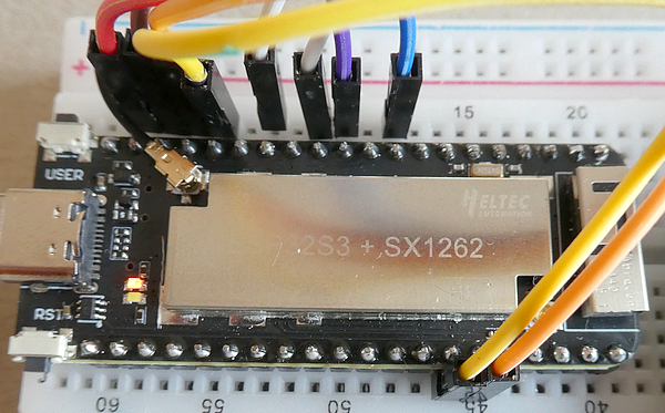
Other settings
These are the pin mappings for the Boot (“PRG/USER”) button and the onboard LED:
BOOT_BUTTON_PIN  - GPIO  0
LED_PIN          - GPIO 35
Vext_CONTROL_PIN - GPIO 36
The internal ESP32-S3 chip temperature is read out depending on the ESP32 Arduino version:
/**
 * @brief Measures esp32 chip temperature
 *
 * @return float with temperature in degrees celsius.
*/
//float heltec_temperature() {
float readEsp32S3InternalTemperature() {
  float result = 0;
  // If temperature for given n below this value,
  // then this is the best measurement we have.
  int cutoffs[5] = { -30, -10, 80, 100, 2500 };
#if ESP_ARDUINO_VERSION_MAJOR >= 3
  int range_start[] = { -40, -30, -10, 20, 50 };
  int range_end[] = { 20, 50, 80, 100, 125 };
  temperature_sensor_handle_t temp_handle = NULL;
  for (int n = 0; n < 5; n++) {
    temperature_sensor_config_t temp_sensor_config = TEMPERATURE_SENSOR_CONFIG_DEFAULT(range_start[n], range_end[n]);
    ESP_ERROR_CHECK(temperature_sensor_install(&temp_sensor_config, &temp_handle));
    ESP_ERROR_CHECK(temperature_sensor_enable(temp_handle));
    ESP_ERROR_CHECK(temperature_sensor_get_celsius(temp_handle, &result));
    ESP_ERROR_CHECK(temperature_sensor_disable(temp_handle));
    ESP_ERROR_CHECK(temperature_sensor_uninstall(temp_handle));
    if (result <= cutoffs[n]) break;
  }
#else
  // We start with the coldest range, because those temps get spoiled
  // the quickest by heat of processor waking up.
  temp_sensor_dac_offset_t offsets[5] = {
    TSENS_DAC_L4,  // (-40°C ~  20°C, err <3°C)
    TSENS_DAC_L3,  // (-30°C ~  50°C, err <2°C)
    TSENS_DAC_L2,  // (-10°C ~  80°C, err <1°C)
    TSENS_DAC_L1,  // ( 20°C ~ 100°C, err <2°C)
    TSENS_DAC_L0   // ( 50°C ~ 125°C, err <3°C)
  };
  for (int n = 0; n < 5; n++) {
    temp_sensor_config_t temp_sensor = TSENS_CONFIG_DEFAULT();
    temp_sensor.dac_offset = offsets[n];
    temp_sensor_set_config(temp_sensor);
    temp_sensor_start();
    temp_sensor_read_celsius(&result);
    temp_sensor_stop();
    if (result <= cutoffs[n]) break;
  }
#endif
  return result;
}
Summary
It is not too difficult to work with I2C or SPI interfaces on a Heltec Wireless Stick Lite V3 device.
Source code of the apps
You find the complete code of the app in my GitHub repository.
Please note that the repository contains code for both Heltec Wireless Stick V3 and Heltec Wireless Stick Lite V3 variants.
Happy coding.
메타데이터
- post_id
- 246fecefef8a
- slug
- how-to-connect-a-tft-display-spi-interface-and-a-bme280-sensor-i2c-interface-to-a-heltec-246fecefef8a
- url
- https://medium.com/@androidcrypto/how-to-connect-a-tft-display-spi-interface-and-a-bme280-sensor-i2c-interface-to-a-heltec-246fecefef8a
- canonical_url
- https://medium.com/@androidcrypto/how-to-connect-a-tft-display-spi-interface-and-a-bme280-sensor-i2c-interface-to-a-heltec-246fecefef8a
- author_url
- https://medium.com/@androidcrypto
- status
- ok
- fetched_at
- 2026-06-26 21:52:29