1/2 Encoding: Sending Bits on Wires
In modern digital systems, everything begins as binary data containing streams of 0s and 1s. But moving those bits from one device to…
1/2 Encoding: Sending Bits on Wires
Image by the author
In modern digital systems, everything begins as binary data containing streams of 0s and 1s. But moving those bits from one device to another is not as simple as it sounds. Whether it’s communication between chips on a circuit board or across long-distance networks, data must be translated into physical signals that can travel reliably. This process is known as encoding and it forms the foundation of all digital communication systems.
Digital devices cannot transmit raw binary directly. Instead, they rely on physical properties ( primarily voltage ) to represent data on transmission media like wires. Encoding transforms binary information into these electrical signals so that receivers can correctly interpret the transmitted data. This process is essential across multiple scales from communication within a microchip to connections between devices across buildings.
Volatage Level based Encoding
Although both current and voltage can be used to represent data, voltage is preferred due to its efficiency and stability. Current tends to vary with distance and consumes more power since it changes with the medium resistence. However selecting voltage levels involves trade-offs:
- Lower voltages reduce power consumption and improve safety
- Higher voltages increase resistance to noise and signal degradation
Standard voltage levels such as 5V and 3.3V are widely used due to historical adoption and cost efficiency.
The simplest encoding scheme assigns high voltage → 1 and low voltage → 0. The receiver samples the signal at regular intervals to decode the data. But this introduces a major challenge of clock synchronization. If the sender and receiver are not perfectly aligned in time, the receiver may interpret bits incorrectly.

Process of digital to digital conversion
One solution is to introduce a separate clock signal which tells the receiver exactly when to read the data. While effective this approach requires additional wiring and increases system complexity and cost. In practice transmitting signals over wires introduces several issues than clock synchronization :
- DC Balance : An imbalance in the number of 0s and 1s can shift the signal baseline making it difficult for the receiver to distinguish between levels.
- Noise : Electrical noise from thermal effects, nearby devices or electromagnetic interference can corrupt signals.
- Attenuation : Signal strength decreases as it travels through wires due to resistance, especially over long distances.
- Dispersion : Signals can spread out over time causing bits to overlap and making them harder to decode.
These challenges highlight the limitations of simple encoding schemes. To reduce hardware complexity while avoiding above limitations for some extent, systems often attempt to extract the clock from the data itself by observing signal transitions.
But this approach fails when there are long sequences of identical bits (ex: continuous 0s or 1s) as there are no transitions to synchronize the clock.
Solution : Asynchronous Communication or Re-sync on Each Short Message
An alternative approach is asynchronous communication where each data transmission includes :
- A start bit to signal the beginning
- One or more stop bits to mark the end
This allows the receiver to resynchronize for each message and ideal for irregular data transmission though there is increased overhead due to extra control bits. Protocols like UART and RS-232 rely heavily on this method.
Alternative Method : Encoding with Transitions Instead of Levels
To improve synchronization, encoding schemes can use signal transitions instead of fixed voltage levels. Common techniques include;
1)NRZ (Non-Return to Zero): High voltage for 1, low voltage for 0
2) NRZI: Transition for 1, no transition for 0.
3) Manchester Encoding: Up transition for 1, down transition for 0

Illustration fo Encoding Schemes
Manchester encoding ensures regular transitions improving clock recovery but requires a higher data rate.
This can be modified further into more sophisticated schemes address synchronization and noise challenges:
1)Differential Manchester: Transition either up or down each cycle. Repeat previous transition if 0, invert if 1.
2) Bipolar AMI: 0 is no voltage, 1s alternate between positive and negative voltage levels.
3) Pseudoternary: 1 is no voltage, 0s alternate between positive and negative voltage levels
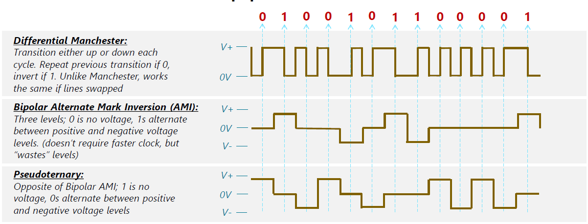
Illustration of Encoding Schemes
While effective, these techniques often increase complexity or require additional resources.
Alternative Method : Codeword-Based Encoding
Another strategy is to map binary data into codewords with an eliminator at the end of each codeword. But it reduce efficiency by increasing the number of transmitted bits.
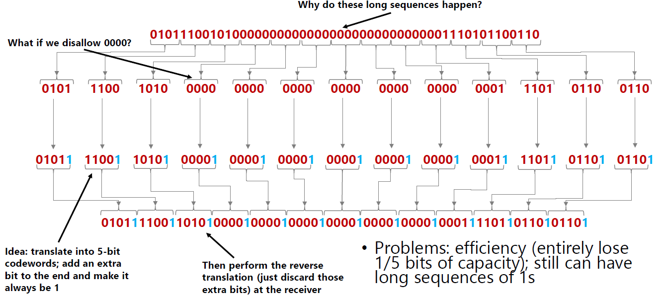
Sample Example of Codeword based Encoding
A more optimized approach is 4B/5B encoding where every 4 bits are converted into a 5-bit codeword. Codewords are at most one leading 0, at most two trailing 0s, never more than three consecutive 0s and transmit with NRZI.

4B/5B Lookup Table
This method prevents long runs of zeros and ensures sufficient transitions for synchronization. This concept also extends to more advanced schemes like 8B/10B (used in digital media and networking) and 64B/66B (used in high-speed Ethernet).
Different encoding techniques are used depending on the application. High speed communication requires complex encoding for reliability and efficiency while short distance values simpler and low power methods. The choice of encoding scheme depends on balancing performance, cost and hardware complexity.
Encoding techniques are implemented within communication protocols that define how devices interact.
1)I2C (Inter-Integrated Circuit) : Two-wire protocol (data + clock) + Supports multiple devices via addressing
2) SPI (Serial Peripheral Interface) : Faster than I2C + Requires separate chip-select lines + Used for high-speed peripherals
3) UART (Universal Asynchronous Receiver/Transmitter) : No shared clock (asynchronous) + Configurable parameters like baud rate and parity
4) GPIO (General Purpose Input/Output) : Simplest interface (on/off signals) + Used for basic control like LEDs and switches
5) 100BASE-TX (Fast Ethernet) : 4B/5B Encoding + NRZI signaling + Prevents long zero sequences + Ensures reliable clock synchronization
6) 1000BASE-T / 1000BASE-X (Gigabit Ethernet) : 8B/10B Encoding (fiber) / PAM-5 (copper) + Supports higher data rates + Maintains signal integrity and DC balance
7) Gigabit Ethernet (10GBASE and above) : 64B/66B Encoding + High efficiency with low overhead + Used in modern high-speed networks
Encoding is far more than just converting bits into signals as it is a carefully engineered process that ensures reliable communication in the presence of noise, signal los, and synchronization challenges. Understanding these methods provides valuable insight into how modern digital systems communicate from tiny embedded devices to high-speed global networks.
메타데이터
- post_id
- 2b445de87498
- slug
- 1-2-encoding-sending-bits-on-wires-2b445de87498
- url
- https://medium.com/illumination/1-2-encoding-sending-bits-on-wires-2b445de87498
- canonical_url
- https://medium.com/illumination/1-2-encoding-sending-bits-on-wires-2b445de87498
- author_url
- https://medium.com/@vishvadiniravihari
- status
- ok
- fetched_at
- 2026-07-11 21:05:18