Controlling DC Motors with ESP-IDF: A Comprehensive Guide
In this article, we are exploring how to control a DC motor using the ESP32 microcontroller with the ESP-IDF framework. We’ll provide a…
Controlling DC Motors with ESP-IDF: A Comprehensive Guide
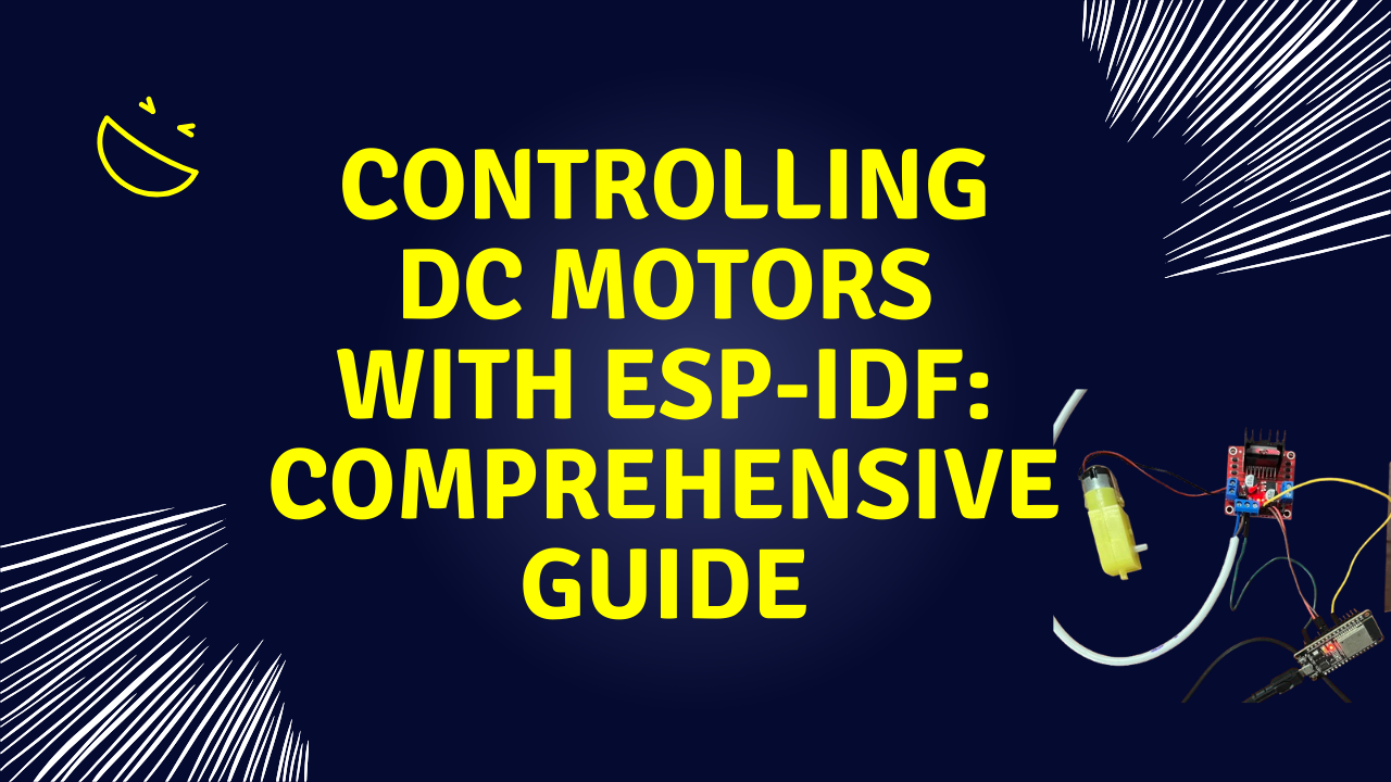
In this article, we are exploring how to control a DC motor using the ESP32 microcontroller with the ESP-IDF framework. We’ll provide a detailed explanation of the code, allowing you to change the example to your specific application.
Whether you’re a beginner or an experienced developer, this guide aims to equip you with the knowledge to effectively control motors using ESP-IDF.
Controlling motors is a fundamental task in robotics and automation projects.
Hardware Components
- ESP32 Development Board
- 12V DC Motor
- L298N Motor Driver
- Power Supply (12V)
- Connecting Wires
- 2 core wire
- 3 core wire with 3 pin plug
Circuit Diagram

Understanding the Code
The code utilizes the ESP-IDF framework to control a DC motor’s speed and direction using PWM signals and GPIO pins. Let’s break down the key components of the code,
Setting Up GPIO Pins
#define MOTOR_IN1_PIN   GPIO_NUM_27  // IN1 pin connected to motor driver
#define MOTOR_IN2_PIN   GPIO_NUM_26  // IN2 pin connected to motor driver
#define MOTOR_ENABLE_PIN GPIO_NUM_32 // Enable pin for PWM control

// Configure GPIO for motor direction control
esp_rom_gpio_pad_select_gpio(MOTOR_IN1_PIN);
gpio_set_direction(MOTOR_IN1_PIN, GPIO_MODE_OUTPUT);
esp_rom_gpio_pad_select_gpio(MOTOR_IN2_PIN);
gpio_set_direction(MOTOR_IN2_PIN, GPIO_MODE_OUTPUT);- MOTOR_IN1_PIN and MOTOR_IN2_PIN: Control the motor’s direction by setting high or low signals.
- MOTOR_ENABLE_PIN: Controls the motor’s speed using PWM.
- GPIO Configuration: The ‘gpio_set_direction()’ function sets the specified pins as outputs.
Configuring PWM with LEDC
#define MOTOR_PWM_FREQ  5000                  // Frequency in Hz for PWM
#define MOTOR_PWM_CHANNEL LEDC_CHANNEL_0.     //Selecting the channel
#define MOTOR_PWM_MODE   LEDC_HIGH_SPEED_MODE
#define MOTOR_PWM_TIMER  LEDC_TIMER_0
#define MOTOR_PWM_RES    LEDC_TIMER_10_BIT    // PWM resolution (10-bit)
#define MAX_DUTY_CYCLE   1023                 // Maximum duty cycle for 10-bit resolution

// Configure PWM timer
ledc_timer_config_t pwm_timer = {
    .speed_mode       = MOTOR_PWM_MODE,
    .duty_resolution  = MOTOR_PWM_RES,
    .timer_num        = MOTOR_PWM_TIMER,
    .freq_hz          = MOTOR_PWM_FREQ,
    .clk_cfg          = LEDC_AUTO_CLK
};
ledc_timer_config(&pwm_timer);

// Configure PWM channel
ledc_channel_config_t pwm_channel = {
    .gpio_num       = MOTOR_ENABLE_PIN,
    .speed_mode     = MOTOR_PWM_MODE,
    .channel        = MOTOR_PWM_CHANNEL,
    .intr_type      = LEDC_INTR_DISABLE,
    .timer_sel      = MOTOR_PWM_TIMER,
    .duty           = 0,
    .hpoint         = 0
};
ledc_channel_config(&pwm_channel);- LEDC Module: ESP32’s LED PWM Controller (LEDC) provides PWM functionality.
- PWM Frequency: Set to 5 kHz, suitable for motor control.
- PWM Resolution: 10 bits, allowing duty cycles from 0 to 1023.
- Timer and Channel Configuration: Initializes the PWM timer and channel with the specified settings.
Controlling Motor Direction
int direction = 1;  // 1 for clockwise, 0 for anticlockwise

// Set motor direction with brief disable between direction changes
if (direction == 1) {
    // Set for clockwise
    gpio_set_level(MOTOR_IN1_PIN, 1);
    gpio_set_level(MOTOR_IN2_PIN, 0);
    printf("Direction: Clockwise\n");
} else {
    // Set for anticlockwise
    gpio_set_level(MOTOR_IN1_PIN, 0);
    gpio_set_level(MOTOR_IN2_PIN, 1);
    printf("Direction: Anticlockwise\n");
}- Direction Control: By setting ‘IN1’ and ‘IN2’ to different logic levels, we control the direction of the motor.
- Clockwise: ‘IN1’ high, ‘IN2’ low.
- Anticlockwise: ‘IN1’ low, ‘IN2’ high.
- Print Statements are useful for debugging and monitoring the motor’s state.
Adjusting Duty Cycle for Speed Control
int duty_cycle = 700;  // Starting duty cycle

// Set PWM duty cycle to control speed
ledc_set_duty(MOTOR_PWM_MODE, MOTOR_PWM_CHANNEL, duty_cycle);
ledc_update_duty(MOTOR_PWM_MODE, MOTOR_PWM_CHANNEL);

// Increase the duty cycle for speed control
duty_cycle += 10; // Increase speed gradually
printf("Duty Cycle: %d\n", duty_cycle);

if (duty_cycle > MAX_DUTY_CYCLE) {
    // Briefly disable motor between direction changes
    gpio_set_level(MOTOR_IN1_PIN, 0);
    gpio_set_level(MOTOR_IN2_PIN, 0);
    vTaskDelay(pdMS_TO_TICKS(100)); // Short delay to stop

    // Reset duty cycle and toggle direction
    duty_cycle = 700;
    direction = !direction;
    printf("Toggling direction\n");
}

vTaskDelay(pdMS_TO_TICKS(200)); // Delay for observation- Duty Cycle Adjustment: The ‘duty_cycle’ variable controls the motor’s speed. Increasing it increases the motor’s speed.
- Maximum Duty Cycle: Capped at ‘1023’ for 10-bit resolution.
- Direction Toggle: When the duty cycle exceeds the maximum, the motor stops briefly, and the direction is toggled.
- Introduced using ‘vTaskDelay’ for controlled timing between operations.
Complete Code
Here is the full code incorporating all the elements discussed,
#include <stdio.h>
#include "freertos/FreeRTOS.h"
#include "freertos/task.h"
#include "driver/ledc.h"  // For PWM control
#include "driver/gpio.h"  // For GPIO control

#define MOTOR_IN1_PIN   GPIO_NUM_27  // IN1 pin connected to motor driver
#define MOTOR_IN2_PIN   GPIO_NUM_26  // IN2 pin connected to motor driver
#define MOTOR_ENABLE_PIN GPIO_NUM_32 // Enable pin for PWM control

#define MOTOR_PWM_FREQ  5000                  // Frequency in Hz for PWM
#define MOTOR_PWM_CHANNEL LEDC_CHANNEL_0
#define MOTOR_PWM_MODE   LEDC_HIGH_SPEED_MODE
#define MOTOR_PWM_TIMER  LEDC_TIMER_0
#define MOTOR_PWM_RES    LEDC_TIMER_10_BIT    // PWM resolution (10-bit)
#define MAX_DUTY_CYCLE   1023                 // Maximum duty cycle for 10-bit resolution

extern "C" void app_main(void) {
    // Configure GPIO for motor direction control
    esp_rom_gpio_pad_select_gpio(MOTOR_IN1_PIN);
    gpio_set_direction(MOTOR_IN1_PIN, GPIO_MODE_OUTPUT);
    esp_rom_gpio_pad_select_gpio(MOTOR_IN2_PIN);
    gpio_set_direction(MOTOR_IN2_PIN, GPIO_MODE_OUTPUT);

    // Configure PWM timer
    ledc_timer_config_t pwm_timer = {
        .speed_mode       = MOTOR_PWM_MODE,
        .duty_resolution  = MOTOR_PWM_RES,
        .timer_num        = MOTOR_PWM_TIMER,
        .freq_hz          = MOTOR_PWM_FREQ,
        .clk_cfg          = LEDC_AUTO_CLK
    };
    ledc_timer_config(&pwm_timer);

    // Configure PWM channel
    ledc_channel_config_t pwm_channel = {
        .gpio_num       = MOTOR_ENABLE_PIN,
        .speed_mode     = MOTOR_PWM_MODE,
        .channel        = MOTOR_PWM_CHANNEL,
        .intr_type      = LEDC_INTR_DISABLE,
        .timer_sel      = MOTOR_PWM_TIMER,
        .duty           = 0,
        .hpoint         = 0
    };
    ledc_channel_config(&pwm_channel);

    int duty_cycle = 700;
    int direction = 1;  // 1 for clockwise, 0 for anticlockwise

    while (true) {
        // Set motor direction
        if (direction == 1) {
            gpio_set_level(MOTOR_IN1_PIN, 1);
            gpio_set_level(MOTOR_IN2_PIN, 0);
            printf("Direction: Clockwise\n");
        } else {
            gpio_set_level(MOTOR_IN1_PIN, 0);
            gpio_set_level(MOTOR_IN2_PIN, 1);
            printf("Direction: Anticlockwise\n");
        }

        // Set PWM duty cycle to control speed
        ledc_set_duty(MOTOR_PWM_MODE, MOTOR_PWM_CHANNEL, duty_cycle);
        ledc_update_duty(MOTOR_PWM_MODE, MOTOR_PWM_CHANNEL);

        // Increase the duty cycle for speed control
        duty_cycle += 10; // Increase speed gradually
        printf("Duty Cycle: %d\n", duty_cycle);

        if (duty_cycle > MAX_DUTY_CYCLE) {
            // Briefly disable motor between direction changes
            gpio_set_level(MOTOR_IN1_PIN, 0);
            gpio_set_level(MOTOR_IN2_PIN, 0);
            vTaskDelay(pdMS_TO_TICKS(100)); // Short delay to stop

            // Reset duty cycle and toggle direction
            duty_cycle = 700;
            direction = !direction;
            printf("Toggling direction\n");
        }

        vTaskDelay(pdMS_TO_TICKS(200)); // Delay for observation
    }
}
Important Points and Best Practices
- Use Appropriate Power Supplies: Ensure that the motor driver and motor have a suitable power supply separate from the ESP32 to prevent overloading the microcontroller.
- Common Ground: Connect the ground of the ESP32 and the motor driver to establish a common reference point for signal levels.
- Motor Driver Compatibility: Verify that your motor driver is compatible with the logic levels of the ESP32 (3.3V). Some drivers require 5V logic levels, which may need level-shifting circuits.
- PWM Frequency Selection: Choose a PWM frequency that balances motor noise and responsiveness. Higher frequencies can reduce audible noise but may affect the driver’s performance.
- Handling Inductive Loads: Motors are inductive loads and can generate voltage spikes. Ensure that your motor driver has built-in protection to bear them.
- GPIO Pin Limitations: Some GPIO pins on the ESP32 have specific limitations. Consult the ESP32 datasheet to avoid conflicts.
Adapting the Code to Your Application
- Changing PWM Resolution: Modify ‘MOTOR_PWM_RES’ to change the resolution. Remember to adjust ‘MAX_DUTY_CYCLE’ accordingly. You can adjust it between 8–16. If you need 12 bit, you can change the below lines accordingly,
#define MOTOR_PWM_RES    LEDC_TIMER_12_BIT // For 12-bit resolution
#define MAX_DUTY_CYCLE 4095 // Maximum for 12-bit- Adjusting Speed Ramp Rate: Change the increment value and delay in the duty cycle adjustment to control how quickly the motor speeds up.
duty_cycle += 5; // Slower speed increase
vTaskDelay(pdMS_TO_TICKS(100)); // Shorter delay for faster ramp-up- Modifying Direction Control: Foe example if your application requires only one direction, remove the direction toggling logic.
// Set motor direction to clockwise only
  gpio_set_level(MOTOR_IN1_PIN, 1);
gpio_set_level(MOTOR_IN2_PIN, 0);- Using Different GPIO Pins: Update the pin definitions to match your hardware setup.
#define MOTOR_IN1_PIN   GPIO_NUM_25
#define MOTOR_IN2_PIN   GPIO_NUM_26
#define MOTOR_ENABLE_PIN GPIO_NUM_27- Implementing Acceleration : For smoother control, implement acceleration profiles using mathematical functions like below.
// Example: Using a sine wave function for acceleration
duty_cycle = (int)(MAX_DUTY_CYCLE * sin(current_time));- If you need to add more channels, you can make up to 16 channels. You can repeat the below snippet with a new channel name and a new enable pin.
    // Configure PWM channel
    ledc_channel_config_t pwm_channel = {
        .gpio_num       = MOTOR_ENABLE_PIN,
        .speed_mode     = MOTOR_PWM_MODE,
        .channel        = MOTOR_PWM_CHANNEL,
        .intr_type      = LEDC_INTR_DISABLE,
        .timer_sel      = MOTOR_PWM_TIMER,
        .duty           = 0,
        .hpoint         = 0
    };
    ledc_channel_config(&pwm_channel);
Conclusion
Controlling a DC motor with the ESP32 using ESP-IDF provides precise control over speed and direction, making it ideal for a variety of applications in robotics and automation.
With this knowledge, you’re well-equipped to explore more advanced motor control techniques and integrate them into your projects.
Hope you enjoyed the article. Please comment below or send us an email to info@protonest.co, if you face any issues when implementing.
We’ve launched the IoT System Design Tool by Protonest to help you build complete IoT systems, with resources along the way.
Use it for your next IoT project and streamline your design process!
https://iot-system-design-tool.protonest.co
Contact us for any consultations or projects related to IoT and embedded systems.
Email: info@protonest.co
Protonest for more details.
Protonest specializes in transforming IoT ideas into reality. We offer prototyping services from concept to completion. Our commitment ensures that your visionary IoT concepts become tangible, innovative, and advanced prototypes.
Our Website: https://www.protonest.co/
Cheers!
메타데이터
- post_id
- 2fee1bc00c0e
- slug
- controlling-dc-motors-with-esp-idf-a-comprehensive-guide-2fee1bc00c0e
- url
- https://medium.com/@protonestiot/controlling-dc-motors-with-esp-idf-a-comprehensive-guide-2fee1bc00c0e
- canonical_url
- https://medium.com/@protonestiot/controlling-dc-motors-with-esp-idf-a-comprehensive-guide-2fee1bc00c0e
- author_url
- https://medium.com/@protonestiot
- status
- ok
- fetched_at
- 2026-07-22 08:09:49