How do I design a secure Data/File transfer platform as a SaaS application?
After about three and a half years of effort, I have just submitted my PhD thesis titled “Context-aware Classification of Static Analysis…
How do I design a secure Data/File transfer platform as a SaaS application?
After about three and a half years of effort, I have just submitted my PhD thesis titled “Context-aware Classification of Static Analysis Warnings Guided by Coding Standards using Machine Learning and Large Language Models”. Then I was thinking, what should I do with the knowledge I have gained through my years of experience and academic qualifications? The best idea I had was “write, write and write …”
Today, I will design a secure Data and file transfer platform with you. It is as simple as follows,

The simplest design
Now, we have sources like SQL databases, File locations, AWS S3 buckets or HTTP APIs. Additionally, we have destinations such as MongoDB databases, Message Queues or SFTP locations (in addition to those previously mentioned). We can use Apache NIFI for the data pipeline. Additionally, the system also allows data anonymisation and type conversion (such as JSON to CSV or XML). Congratulations, we have now designed the simplest application. But wait, what if there is a high volume of data to be processed (Scalability)? What if the only available instance of the data transfer/converter fails or crashes (Availability and reliability)? There are a few problems in our simplest design:
-
Scalability — How far the system can scale with an increase in data
-
Availability — Uptime of the system
-
Reliability — The ability of the system to function correctly over time without unexpected failures
The solution for these problems is redundancy. We create a cluster of instances of the data transfer/converter. However, we are not going to discuss further details on cluster creation today, as it is far from our objective. However, the design is evolving as follows,
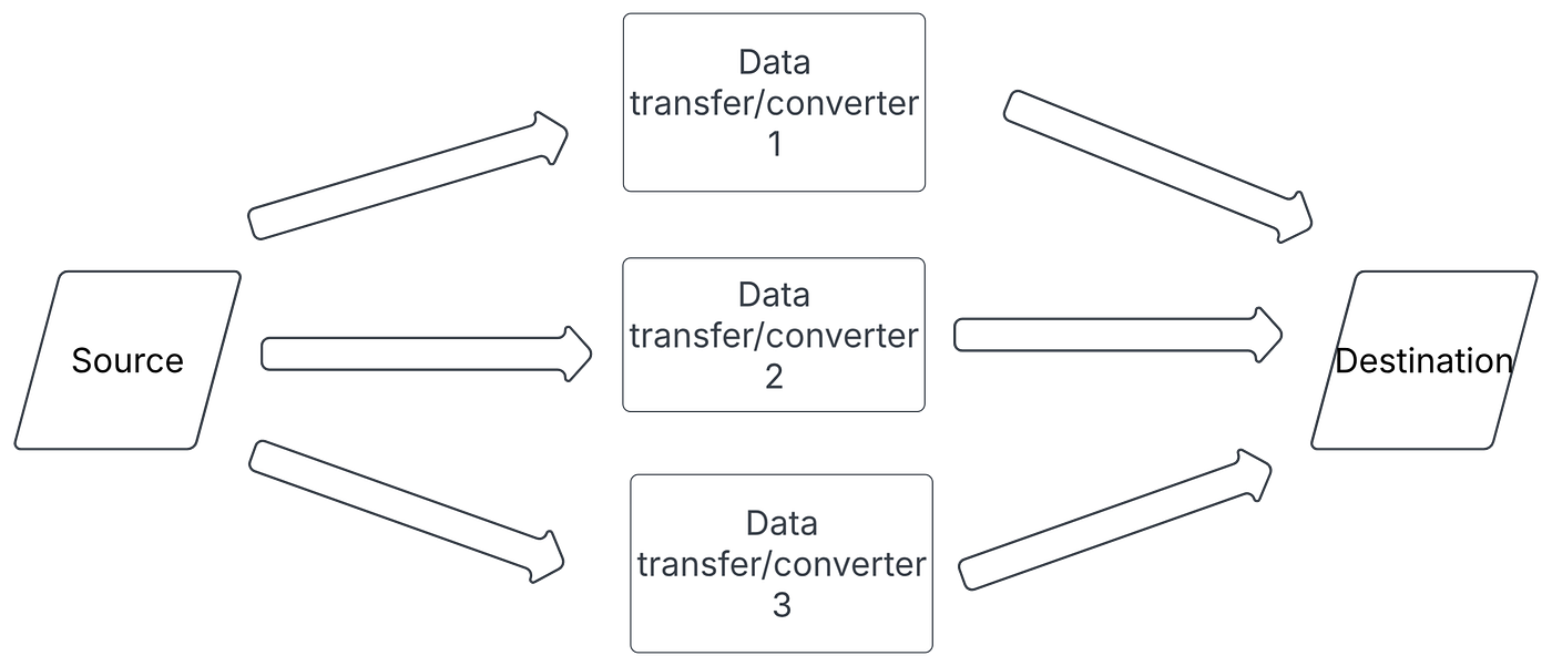
System design with multiple instances of data transfer/converters
Now, the system can process three times more data, and if required, we can add more instances to process even more data (Scalability). Furthermore, if an instance failed, the system works well, and users do not notice any failures (Reliability). Since the system works without any issues and still accepts data to be processed, the system provides high availability. Furthermore, we can deploy this system in a public cloud environment like Azure or AWS, so that the number of processing instances added or removed automatically (Auto Scaling). However, NIFI instances are stateful and shutting down a working instance can lose some data. So, removing a NIFI instance from the cluster is complex. Therefore, we will discuss those additional details later. Congratulations, we created a system to transfer/convert data from sources to the destination.
Now, the system is fine until the size of input items and the size of data items sent to the destination are the same. We can not guarantee against failure occurring outside of the system, like network failures in sources and destinations. Therefore, it is a good idea to keep track of each data item and some of the metadata, such as timestamp, size or some unique identifier, that align with the client agreement. This concept is widely known as data lineage. Therefore, we generate a unique ID using the Redis dataset method explained in this link. Redis is an in-memory key-value store, and we can use it to generate a unique ID by incrementing the current ID by 1 and returning it. This approach is faster than using an auto-incremented ID of RDBMS, as it does not require data to be persisted in hard disks (permanent storage). This approach is simple; however, it is not a scalable solution. But we use this approach for now; if we need a more scalable solution, we can upgrade the same approach to Snowflake’s unique ID-generating approach, which is described in the previous link. The generated data is embedded in the data item in the NiFi, and it will be saved in the MongoDB database with other metadata. We use MongoDB here because it supports write-heavy operations. We will name our current system as part 1, as we need to discuss some other aspects regarding part 1 with the remaining part (part 2) of the system.
System design with a unique ID generator (Part 1)
Now everything is fine, except our designed system is not a SaaS (Software as a Service), where the system supports any authorised user to log into the system and define their own sources, destinations and how the data should be transferred. However, our design does not support these functionalities. So, the proposed system should support at least the following functionalities.
-
The admin of the system should allow adding a new user.
-
The user should be able to log into the system (Authentication), and the user should be allowed to access functionalities assigned by the admin (Authorisation).
-
The user can define Sources and Destinations with required configurations.
-
The user can define the data pipeline with required processing (transferring, anonymisation, type conversion, etc.).
-
The user should be able to monitor the health of their data pipelines.
-
The user should receive notifications if there are any issues in their data pipelines.
Let’s begin with the first two use cases. To manage users, authentication and authorisation, we have two main options: we can build our own system, which is costly to develop as developers need to invest some time to develop the system, and more importantly, it can be more prone to failures. However, developing such a system on our own provides us with better flexibility. On the other hand, we can use existing well-established open source software such as Keycloak. Keycloak provide better reliability and supports industry-standard protocols like OpenID Connect (OIDC), OAuth 2.0, and SAML 2.0. Therefore, we use Keycloak for the first two use cases. Additionally, we use Nginx as a reverse proxy, defining all backend servers by unique URLs. Now the following design diagram supports all six use cases identified previously.
Part 2 of the system design (Part 1 is represented as one box at the top)
Now, the admin of the system can add users to the system, and users can log into the system with their credentials. Each user has a unique ID in the system, and each has a separate workspace. However, all the users share the same resources, and we will discuss how to assign limits for resource consumption on another day. The frontend application allows users to define sources, destinations, and data pipelines, and once they submit the final design, it will transfer to NIFI Manager. The NIFI manager then uses APIs of Apache NiFi to define the dataflow within the specific user’s workspace. Additionally, NIFI Manager will run periodic health checks for each dataflow, their backpressures, and save them in the MongoDB database. Additionally, that data will be sent to the backend application, so that the data can be displayed in the frontend dashboard. Now, in the MongoDB database, the following information is available.
-
Unique IDs of each data item with their metadata.
-
Anonymisation information, which needs to be used to deanonymise.
-
Health status history data of each dataflow with their time.
-
System logs.
-
Dataflow creation information, in case the NiFi cluster is destroyed and all the dataflow information is deleted (This is very rare to occur, but having a backup plan is always good).
We created two microservices: one for the front-end application and another to manage NiFi flows. The NIFI manager can manage NiFi instances through REST APIs. For example, we can send a request to create data from the front-end, and the request is sent to the NIFI manager through the backend service. The NiFi manager then converts the request into a set of REST API calls, executing them sequentially while ensuring the successful completion of each request (for example, creating a specific processor in NiFi). Since the NIFI manager takes a longer time to execute a request from the frontend, the communication between the Backend service and the NiFi Manager is asynchronous. Furthermore, we implement a rate limiter (Globally, not for specific users) for the NiFi manager to reduce the load for NiFi data flow modifications.
Furthermore, you may have one concern now, we designed the Part 1 of the system for high availability and scalability, making the NiFi cluster. However, we did not think of the availability and scalability of the Part 2. This is because there are not many throughput requirements for the Part 2. The most important part of the system is Part 2, and even in an unfortunate situation, we can shut down the Part 2 to reduce resource requirements for our system (Graceful degradation).
Drawbacks of this system design
- Single Point of Failure in MongoDB and all the data is saved in one database. However, we might need to transfer log data into Elastic Search, based on future requirements.
- Configuration information for sources and destinations is defined in the frontend. That data was saved as plain text, and that information contains credential data such as usernames, passwords, and tokens as well, posing a security threat.
- In NiFi, one client might send a large set of files or data, causing other clients to wait longer.
Congratulations, we designed our secure Data/File transfer platform as a SaaS application. Please comment on your ideas and opinions. So it helps me a lot to write more posts like this.
*Discreminer — Grammarly was used to check for grammar mistakes. No AI, except Grammarly, was used to write this article.
메타데이터
- post_id
- 3487a412c056
- slug
- how-do-i-design-a-secure-data-file-transferring-platform-as-a-saas-application-3487a412c056
- url
- https://medium.com/@lakmalv91/how-do-i-design-a-secure-data-file-transferring-platform-as-a-saas-application-3487a412c056
- canonical_url
- https://medium.com/@lakmalv91/how-do-i-design-a-secure-data-file-transferring-platform-as-a-saas-application-3487a412c056
- author_url
- https://medium.com/@lakmalv91
- status
- ok
- fetched_at
- 2026-06-11 22:20:54