Painting with Logic: My Journey Controlling RGB LEDs on the Nexys A7 FPGA Board
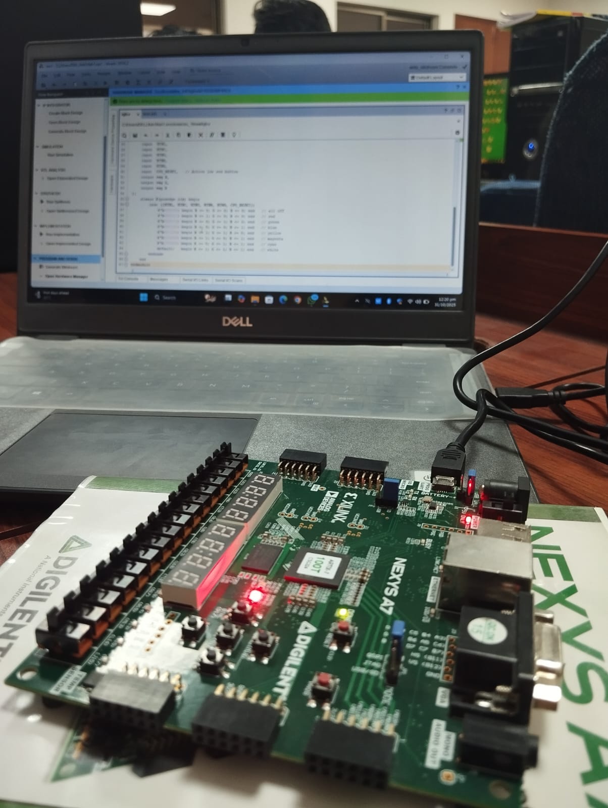
The moment I pressed that button and watched the LED glow a perfect cyan, I realized I wasn’t just turning on a light. I was sculpting…
Painting with Logic: My Journey Controlling RGB LEDs on the Nexys A7 FPGA Board
The moment I pressed that button and watched the LED glow a perfect cyan, I realized I wasn’t just turning on a light. I was sculpting logic.
It’s strange how a single flicker of color can make hours of debugging, pin mapping, and simulation suddenly feel worth it. That’s the magic of FPGA design, where code becomes circuit, and abstract logic transforms into something you can actually see.
This is the story of how a simple lab task assigning IO pins for tri-color RGB LED control on the Nexys A7 board turned into one of the most enlightening experiences of my digital design journey.
The Challenge: Making Colors from Logic
At first glance, the assignment sounded deceptively simple:
“Control the RGB LEDs on the Nexys A7 board by assigning IO pins and implementing logic in Verilog.”
I thought, okay, easy, just turn the LEDs on and off. But as soon as I opened the Nexys A7 reference manual, reality kicked in.
Each RGB LED on the board isn’t just one LED. It’s actually three LEDs packed together, red, green, and blue. By combining these three signals, you can produce up to eight distinct colors (including white and black).
- Black (000) all off
- Red (100)
- Green (010)
- Blue (001)
- Yellow (110)
- Magenta (101)
- Cyan (011)
- White (111)
That’s the theory. But FPGAs aren’t like Arduino, there’s no digitalWrite() or analogWrite(). Everything happens at the logic gate level. That meant I had to describe hardware that produces these color combinations, and then map it to the correct physical pins.
Step One: Understanding the Board
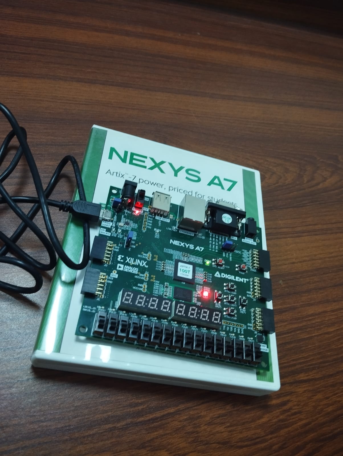
The Nexys A7 is based on the Xilinx Artix-7 FPGA, and it features two onboard tri-color RGB LEDs. These LEDs are controlled through transistors, which means the signals are active low.
Here’s the catch:
- Writing a logic ‘1’ turns the LED ON.
- Writing a logic ‘0’ turns it OFF.
This feels backwards at first, but it’s because the transistors invert the control logic. Also, the manual had a funny warning:
“Driving any input continuously high will result in an uncomfortably bright LED.”
Translation: never use 100% duty cycle.
For my first implementation, though, I kept it simple full brightness, full color, no PWM. I just wanted to understand the basics before diving into brightness control.
Step Two: Designing the Logic in Verilog
This is where the fun really began. I created a Verilog module that used switches as input and controlled the three color channels accordingly. Each combination of the three switches represented one of the eight colors.
Here’s the module that brought it all to life:
module RGB_Controller(
    input [2:0] SW,
    output reg R, G, B
);
always @(*) begin
    case(SW)
        3'b000: {R,G,B} = 3'b000;
        3'b001: {R,G,B} = 3'b001;
        3'b010: {R,G,B} = 3'b010;
        3'b011: {R,G,B} = 3'b011;
        3'b100: {R,G,B} = 3'b100;
        3'b101: {R,G,B} = 3'b101;
        3'b110: {R,G,B} = 3'b110;
        3'b111: {R,G,B} = 3'b111;
    endcase
end
endmodule
I remember simulating it in Vivado and watching the waveforms change exactly as I expected. Every time a switch bit flipped, the corresponding LED output toggled. But simulation is just theory the real test is making the actual LED on the board respond.
Step Three: The Bridge Between Logic and Reality
Here’s the part that many new FPGA learners underestimate: the XDC file.
In software, variables and memory addresses are abstracted away you don’t really care where things live. In FPGA design, you must explicitly tell the hardware which pin each signal connects to.
That’s what the Xilinx Design Constraints (XDC) file does it connects your logical ports (R, G, B) to physical pins on the board.
Here’s the snippet from my constraints file:
# RGB LED connections
set_property PACKAGE_PIN T8 [get_ports {R}]
set_property PACKAGE_PIN T7 [get_ports {G}]
set_property PACKAGE_PIN U7 [get_ports {B}]
set_property IOSTANDARD LVCMOS33 [get_ports {R}]
set_property IOSTANDARD LVCMOS33 [get_ports {G}]
set_property IOSTANDARD LVCMOS33 [get_ports {B}]
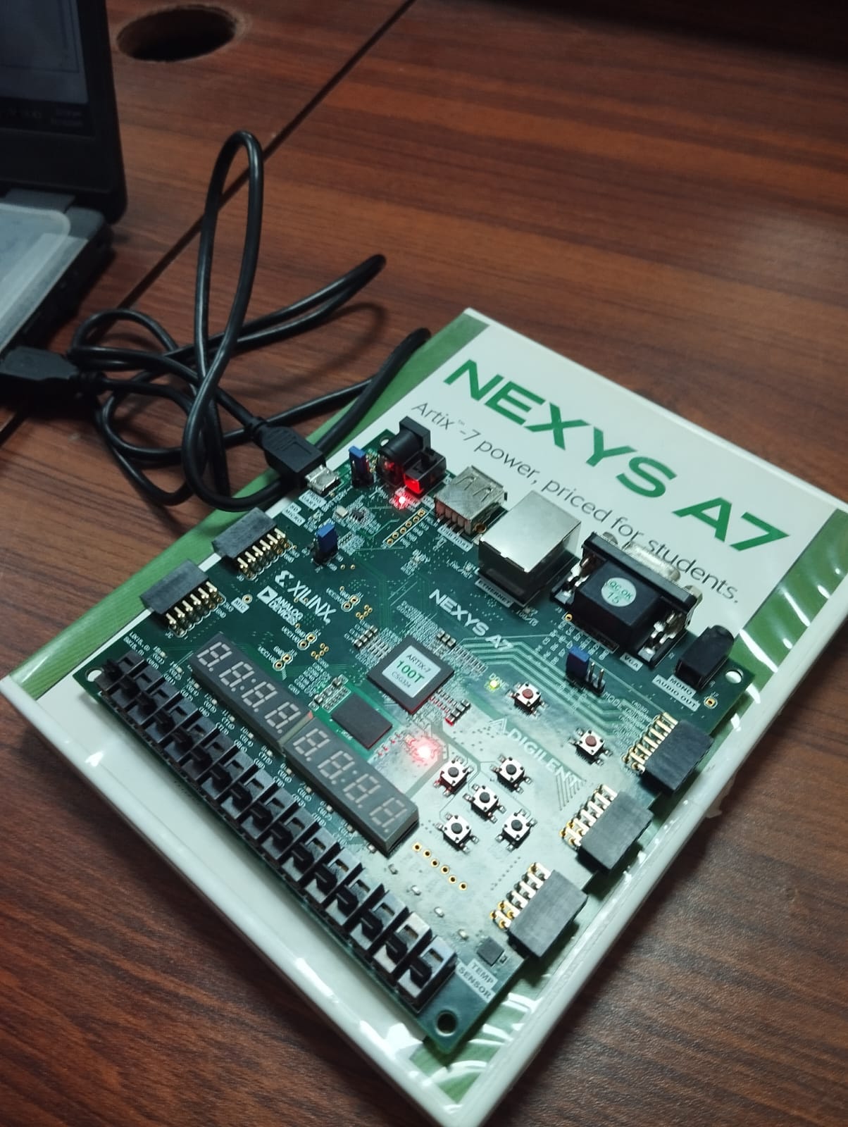
When I first programmed the FPGA, nothing happened. For a few minutes, I thought my Verilog was wrong until I realized I had mistakenly assigned the wrong LED pins (rookie mistake!). After correcting the pin mapping, I pressed Program Device again… and there it was, a glowing red LED. Then green. Then blue. Then, magenta was the exact mix I’d been waiting to see. That one color was my “it works!” moment.
What I Learned Along the Way
1. Hardware Thinks in Parallel
In software, everything happens line by line. In hardware, every process happens simultaneously. It’s not a set of instructions, it’s a network of circuits all responding at once. That one realization changes the way you think forever.
2. Timing Is Everything
When you use always @(posedge clk) In Verilog, you’re not just writing a loop. You’re defining when your circuit updates, synchronizing it with the clock. Without proper timing, you’ll see flickers, glitches, or colors that never stabilize.
3. Constraints Define Reality
No matter how perfect your code is, without an XDC file, the FPGA doesn’t know what’s connected where. The logic exists, but it’s floating in limbo.
4. Debugging Feels Physical
There’s no console, no print statement. Debugging happens with LEDs, waveforms, and careful observation. It’s less about “finding a bug” and more about understanding behavior.
5. Every LED Is a Lesson
That white LED at the end? It wasn’t just a color. It represented correct synthesis, successful mapping, and a deeper understanding of how digital design connects to the physical world.
Taking It Further
Once I got the basics down, I started exploring possibilities:
- Using PWM (Pulse Width Modulation) to control brightness
- Creating color transitions or fade effects
- Synchronizing LEDs with clock pulses or input buttons
- Building a simple color pattern generator
That’s when I truly saw how flexible FPGA design can be. It’s not just about LEDs, it’s about thinking like hardware.
Why It Matters
At first, this project might seem like a small lab exercise, just blinking lights. But in reality, it captures the essence of what makes hardware engineering so unique:
- You think in logic gates, not instructions.
- You connect abstract design to physical outcomes.
- And you see your code exists in the real world.
Those same principles scale up from a single RGB LED to entire communication systems, embedded controllers, and hardware accelerators. Understanding how to assign IO pins and control physical components is the foundation of all of it.
Final Thoughts
That moment when my LED glowed magenta wasn’t just satisfying it was symbolic. It marked the point where my understanding of digital design shifted from theory to reality.
Working with the Nexys A7 taught me that hardware design is both science and art. It’s logic, voltage, and timing, but it’s also creativity, precision, and patience.
Every color I produced was proof that my logic worked. Every signal that reached the correct pin was a small victory in understanding how digital systems breathe life into light.
And to anyone starting their FPGA journey: Start small. Blink an LED. Understand the signals. Because the moment that LED lights up in your chosen color, trust me, you’ll be hooked.
메타데이터
- post_id
- 400aeca6a947
- slug
- painting-with-logic-my-journey-controlling-rgb-leds-on-the-nexys-a7-fpga-board-400aeca6a947
- url
- https://medium.com/@muhammadsafeer025025/painting-with-logic-my-journey-controlling-rgb-leds-on-the-nexys-a7-fpga-board-400aeca6a947
- canonical_url
- https://medium.com/@muhammadsafeer025025/painting-with-logic-my-journey-controlling-rgb-leds-on-the-nexys-a7-fpga-board-400aeca6a947
- author_url
- https://medium.com/@muhammadsafeer025025
- status
- ok
- fetched_at
- 2026-08-06 17:27:03