Breaking Down WebRTC
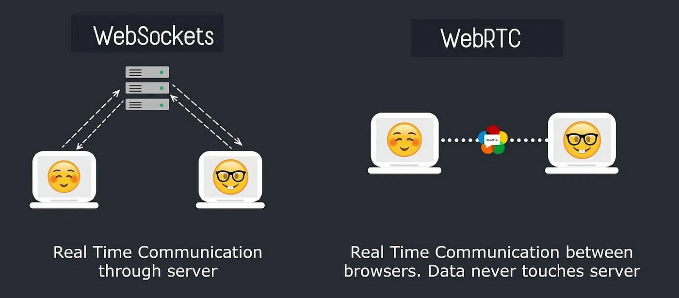
WebRTC (Web Real-Time Communication) connection does not need a server between clients to transfer data, unlike WebSockets. Clients will be…
Breaking Down WebRTC
WebRTC (Web Real-Time Communication) connection does not need a server between clients to transfer data, unlike WebSockets. Clients will be directly communicating with one another, and we call that peer-to-peer connection, which is the connection between clients without the need for a server in the middle. But how does that happen? Let me first introduce to you some essential topics to grasp the main idea behind WebRTC, especially during the “handshake” or connection establishment.
1. UDP
Please refer to this article that defines what UDP is and shows the difference between it and TCP. Keep in mind that WebRTC is mainly built over UDP, while WebSockets is built over TCP.
2. SDP
Session Description Protocol. As the name suggests, it’s a text-based format for describing session information, it just describes how the media (data) will be exchanged in the upcoming WebRTC peer-to-peer connection. So it’s like any “handshake” that happens as an initial setup/preparation before establishing a connection between two parties. Since it’s like a handshake, that concludes that any SDP will typically be divided into an SDP offer and an SDP answer requests or responses. However, you might need to send more than 1 SDP offer to upgrade the connection, like adding video media to an only-voice WebRTC connection.
The inside of an SDP message?
SDP uses various attributes within the message to describe the media capabilities and session details of a WebRTC device. Let’s have a look at some of the most common SDP attributes:
- Version indicates the version of the SDP protocol being used.
- Origin indicates where the message originates from. It includes the username, session ID, and network address.
- Session Name a human-readable name for the session.
- Media Types [ ] indicate what media types are being offered or answered to be transferred between the two parties (audio, video, application/data). Each media type will have its codecs, transport method, and directionality (send, receive, or both).
- Supported Codecs [ ] A codec is a method of compressing and decompressing audio or video (encoder and decoder). So both parties must agree to a specific codec to use.
- Encryption describes how the connection is secured. WebRTC requires encryption to prevent eavesdropping and validate that you’re talking to the intended peer. Encryption supported are DTLS and SRTP, one is for signaling, and the latter is for media, we’ll go through both later on.
- ICE Candidates which we will go deeply into later, but just know that they’re here ;)
And many more of course, but these are the most relevant to emphasize how an SDP offer/answer request/response actually holds all the essential information needed for a WebRTC connection to establish.
Fun activity: You can check this website, which takes the actual raw text of an SDP offer and explains the meaning behind every line in detail.
Signaling
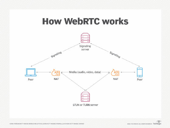
Signaling is just the process of establishing the connection between two clients, AKA it’s the process of sending an SDP offer and receiving an SDP answer. WebRTC itself does not define or implement a way for signaling, it’ll be up to the developer to implement signaling however they want, so you’ll be using external libraries to send your SDP. You can configure your client to send/receive them in any way, however, the most preferred way is to send them via WebSockets, meaning that there must be a server included, even though we just said that WebRTC does not need a server because it’s peer-to-peer, but we both now know that signaling is not part of the WebRTC data transfer process itself.
3. ICE
We’ll discuss what ICE is and why is it important, but first, we need to know the issue, which the ICE comes to solve.
NAT Mapping
WebRTC sends and receives data over UDP protocol, which is a connectionless protocol that just fires data and expects a data fired at any time. Now, we know that for an outgoing request to be sent to an IP, it passes through the NAT, so it maps this internal local IP to a public IP with special port, to know that if a response comes to that public IP:port, it passes it to this internal device.
Private/internal IP       Public IP:port
192.168.1.46 (PC)         203.0.113.50:5123
192.168.1.55 (Phone)      203.0.113.50:4332 #(same IP and different port, for mapping)
It now remembers the public IP/port maps to which internal private IP/port (device)So, for your network to forward a received packet/data to your private device, there has to be mapping for your device and that public IP/port receiving the data. If you’re initiating the sending, there’ll be no issue since the NAT will create that mapping after any outgoing request, but if you’re receiving first, NAT will not have that mapping exist, your public IP/port will receive some data, and doesn’t know where to redirect it in the private network. And that’s the main NAT issue, it’s great for security reasons, but not in UDP connectionless requests that might come without a connection being established (and thus no mapping in the NAT table).
This is where ICE comes into play.
ICE Comes to Help
ICE (Interactive Connectivity Establishment) is the process of successfully mapping a public IP:port to internal device IP, how is it done? Bear with me, this is so exciting...
The main issue is that a client needs a mapping for his current device, to a public IP:port address so that NAT can forward data on that public IP/port to your private device IP. Simply put, just create this NAT table entry by creating a "dummy" request to a server (STUN server) and get that exposed public IP:port (which now has a mapping in the NAT table and any data sent to that IP will be forward to my own device private IP) and send it to the other client during the signaling process for him to send the data to that public IP/port. Voila!
Let’s sum up everything now. Private IP device 192.168.1.200 needs to communicate with another private IP device 192.168.1.300 on a completely different network in another country, both must have a mapping through the NAT table and assign a public IP:port to the device, how to create that mapping? By sending a dummy server request, and get that exposed public IP/port to that server request. Now each client has a public IP:port that it used to send to a dummy server, therefore NAT table automatically creates the mapping, and we know that any data sent to that public IP/port address will be mapped directly to our own private device, because that's where was the dummy server request originated from.
That’s everything, except that the “dummy” STUN server request will typically be more than 1, so we’ll be mapping more than 1 public IP/port to our same private device, to give the other party a kind of choice to select the best working IP to send to, and we call them, ICE Candidates.
There’s a trivial ICE candidates type called Host Candidates which doesn’t need any public IP/port mapping and is only done in the private network between devices and each other.
Note that ICE Candidates are sent in the signaling process in the SDP offer/answer, we mentioned it earlier and said it’ll be covered throughout this article, so here you go.
ICE Servers
- STUN Server: It’s the main method to create the ICE Candidates via exposing NAT public IP/port and the most used, unless NAT is too strict. A client sends a request to a STUN server, NAT creates mapping, STUN server returns what it sees (the mapped public IP/port). Resulted candidates are called srflx candidates.
- TURN server: A very bad choice, which is used in case STUN fails, in case of strict NAT or firewall issues. NAT can be strict such as the symmetric NAT, which maps every outgoing request to a new public
IP:port, which means there won’t be a single publicIP:portto send/receive packets to. TURN server acts as a middleman server, which takes the data from one party and forwards it to the other. Resulted candidates are called relay candidates.
Now we can safely sum up everything to understand how WebRTC combines all these together, to establish a peer-to-peer connection between two parties.
WebRTC Architecture
To have a healthy WebRTC peer-to-peer UDP pipeline, the typical steps will be as follows:
- Configure your SDP object (media types, codes, encryption, …).
- Create your ICE candidates.
- Start the signaling process (send SDP offer or receive one and send SDP answer).
Note that some implementations use Trickle ICE, where ICE candidates are sent one after the other after the SDP offer/answer via the signaling channel.
- Voila.
The architecture itself is so simple and smart, all the understanding lie in the main side concepts. Enjoy UDP’ing.
References
[1] https://www.digitalsamba.com/blog/understanding-sdp-protocol [2] https://www.youtube.com/watch?v=AjLFvHuG0cE [3] https://webrtchacks.github.io/sdp-anatomy/
메타데이터
- post_id
- 44cd5c337482
- slug
- breaking-down-webrtc-44cd5c337482
- url
- https://medium.com/@loayahmed304/breaking-down-webrtc-44cd5c337482
- canonical_url
- https://medium.com/@loayahmed304/breaking-down-webrtc-44cd5c337482
- author_url
- https://medium.com/@loayahmed304
- status
- ok
- fetched_at
- 2026-06-25 16:53:31