Programming a hooded DECODE shooter
In FIRST Tech Challenge DECODE, teams must shoot projectiles into goals from various locations on the field. One method of aiming these…
Programming a hooded DECODE shooter
In FIRST Tech Challenge DECODE, teams must shoot projectiles into goals from various locations on the field. One method of aiming these projectiles is through a hooded flywheel shooter:
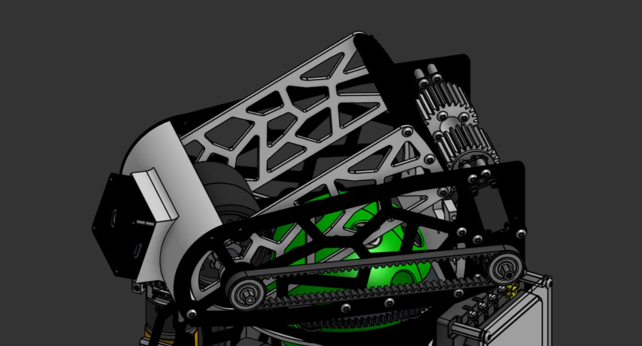
A hooded shooter design from FTC Team #5189 (not mine)
Like traditional flywheel shooters, these rely on a quickly-spinning flywheel to shoot up a ball. However, unlike fixed-angle shooters, they can use a hood to adjust the angle of the ball.
Why use a hooded shooter?
These are very difficult to model analytically, which is why I didn’t discuss them in my previous blog post. However, despite being more complex mechanically, they have the advantage that they allow teams to use the optimal angle for shooting, regardless of launch distance:
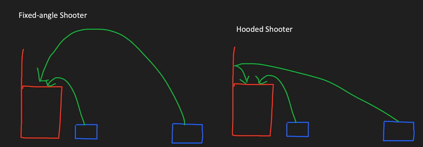
As you can see, the hooded shooter can shoot the projectile at a much more shallow angle when far away from the goal. This limits airtime which reduces the effects of aerodynamics and other sources of error on the ball, while still keeping the same range as a fixed-angle shooter. This should hopefully lead to more accurate, consistent shots, and also make things like shooting while moving easier. Considering these benefits, lets discuss how to program a hooded shooter!
Flywheel Velocity PID
The first step to implementing a hooded shooter is to control the velocity of the flywheel accurately. Unlike a fixed-angle shooter, a hooded shooter simply needs to maintain a constant velocity. Thus, it may be tempting to just set the power to 1.0 and let it spin at full speed. However, this has a critical problem: the speed will change based on the voltage of the battery, which in turn changes based on things like the power draw of your drivetrain. This will result in inconsistent shooting. Instead, you should use a velocity PID controller to accurately reach a speed that you know your flywheel can achieve, even at low battery voltages.
To determine a target speed, apply something like 10V to the motor (hopefully, your voltage doesn’t drop below this). You can do this by applying a power thats proportional to your battery voltage. For example, if your battery voltage is 13.5V, you would apply 10/13.5 = a power of ~0.75 to your motor. Then, measure the velocity with your encoder and save this as your target velocity.
As with pretty much every control system, you use PID to do the control. In this case, you use an integrator which is a PID controller where P and D are zero. That way, any error in the flywheel’s velocity leads to an increase in the motor’s voltage. This is because in velocity control you need to constantly apply a power to the motor to keep it spinning (unlike slides or an arm, where 0 power makes them stay the same), so the integrator needs to add up the velocity error.
You can also add a little bit of P to improve the controller’s transient response — how quickly the flywheel speeds up and slows down when its commanded to spin up or a disturbance occurs (e.g. a ball is launched). Once kI is tuned well I would slowly increase kP and test via a step response (basically tell it to go from 0 to 50% speed and vice versa) and plot the velocity on something like FTC dashboard. For example, here’s a step response of a (pretty terribly tuned) velocity controller I made a while back:
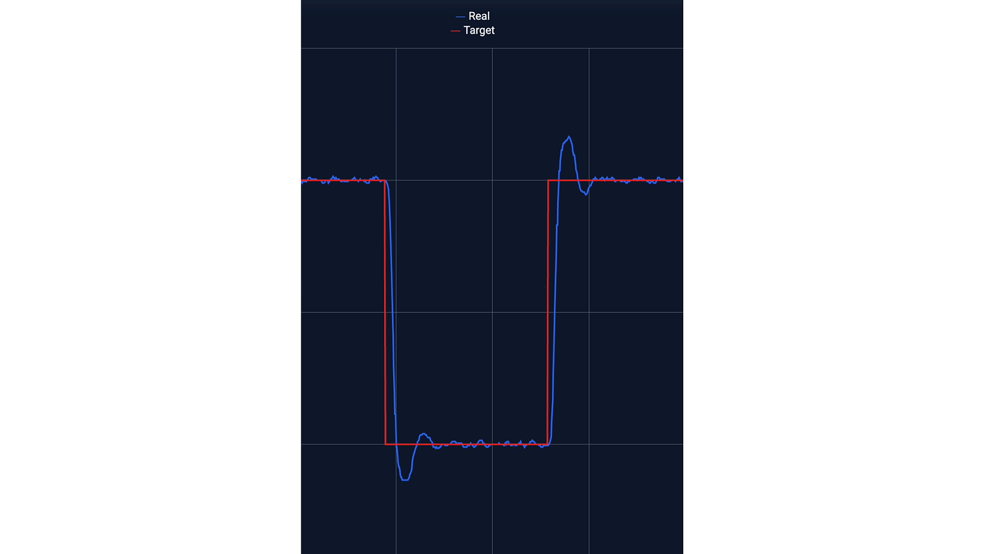
I believe my kI term was way too large and my kP term was slightly too small when I made this
You also want to design your flywheel to have a somewhat high moment of inertia so that disturbances like the ball going through the flywheel affect the speed less and spin-up is smoother.
Aiming at the goal (localization)
This section is copied from my previous blog post
The next programming challenge is aiming at the goal. To do this you need to know your position on the field — a problem called localization. I’ve found that using dead-wheel odometry with something like GoBilda Pinpoint works pretty well in the short term (maybe 30 seconds? do some testing and find out! the judges will love it (: ) but suffers from something called drift in the long term. Essentially, tiny errors in the localization add up over time causing inaccuracies after a lot of driving. To address this, you can use the April tags on the field — the weird things that look like QR codes:
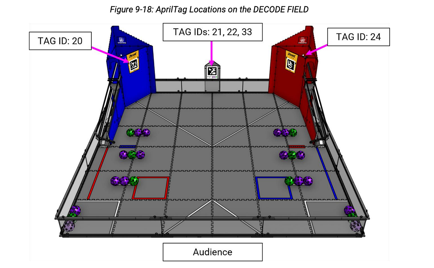
These are called fiducials, and computer vision code can be used to calculate the robot’s position by basically looking at how the corners are squished and twisted on the tag from the robot’s perspective.
There are many ways to determine your position from an April tag, including using the builtin SDK April tag pose estimator with a calibrated webcam or using a Limelight. I haven’t actually compared these so try them out and see which works better! You can simply overwrite your pose with the pose calculated from the April tag, a process called re-localization.
For maximum reliability I would recommend manually re-localizing (requiring the driver to press a button) because things like motion blur and camera delay can make automatically re-localizing error prone. Probably implement an algorithm to verify the new pose is correct too, maybe averaging out multiple values or comparing it to the old pose and ensuring they are roughly similar.
Once you know your position on the field you just need basic trigonometry to determine how to aim your turret or robot. You can use traditional PID, either with the drivetrain’s heading or with your turret to achieve this.
Aiming the Hood
Unfortunately, it is extremely difficult to derive an equation for how to aim the hood since there are so many complex phenomenon going on. Instead, we can use a more experimental approach!
In this experiment, the independent variable is the distance from the target, which is measured by the localizer. The dependent variable is the angle of the hood, which you need to find!
To figure out the angle of the hood you can position the robot at a series of known distances from the goal. Then, run the flywheel velocity PID and shoot while tuning the angle of the hood until the ball consistently goes in. This means that you would want to do several shots at each distance and ensure that they all go in. You can also do things like bouncing off the wall for more consistency. Once you’ve picked an angle for each distance, do two things:
- Write down the hood angle and distance (most likely the hood servo position)
- If you want to shoot while moving:
- You need to have something like an LED on your robot to indicate when the command to feed the ball into your shooter was issued
- Record a slow-mo video of the shot, and make sure to label the video with the shot distance
Make sure to test a lot of distances — at least five, but the more, the merrier! Additionally, make sure to only test distances that encompass the launch zones. Don’t waste time preparing for shots you don’t need to make :)
Once you have data for hood angle vs shot distance, you can either fit a regression or use an InterpLUT. To create a regression, you plot hood angle vs shot distance and use a tool like Excel or Desmos to fit a mathematical equation:
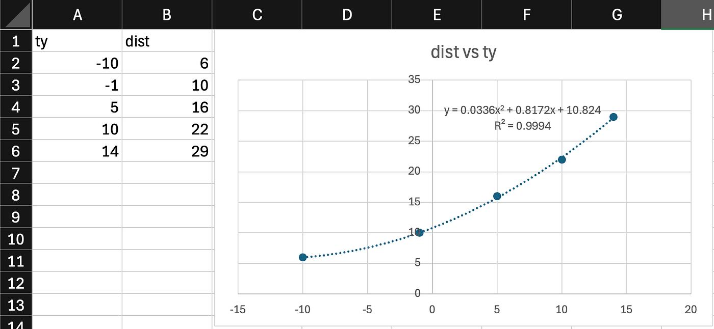
A polynomial regression for our Into The Deep vision code
Then, you can just copy this equation into your code and use it to calculate your hood angle.
The other option is to use an interpolated look-up table (you can find a good implementation on FTCLib). With this one you can just enter your data into your code, and it will linearly interpolate between each data point to calculate the hood angle. However, even if you are using an InterpLUT I would recommend at least plotting the data once, because these graphs help you gain a better understanding of your robot and also help you find any anomalies! (Pro Tip: put this in your engineering portfolio)
Combining it all together
Now that you understand each component of a hooded shooter, here’s how the process to tune one would work:
- Tune the flywheel velocity PID, using a tool like FTC Dashboard
- Record data for hood position vs shot distance
- Fit a regression or use an InterpLUT
To actually shoot, here’s how the process would work in the control loop:
- Update localization (e.g. query pinpoint, re-localize with AprilTags)
- Calculate the hood angle using the InterpLUT/regression, and move the servo to this position
- Spin the flywheel using the velocity controller
- Aim the turret/drivetrain using PID
- If the robot is aimed (e.g. turret/drivetrain error is <5deg) and the flywheel is at an appropriate speed (e.g. <50rpm of error), feed the ball into the shooter!
This method accounts for the time the robot takes to line up, and it also allows you to shoot as fast as possible while still maintaining accuracy, since it waits for the flywheel to spin back up before shooting another projectile.
Side Quest: Turret Hysteresis Control
To shoot while moving, or just to improve the performance of your shooter in general, a good method is to use a turret. However, these have a problem: range discontinuities. Since they can’t turn an infinite amount, at some point you need to flip between one side of the range and the other side of the range (unless you use a slip ring).
With a turret that has a range of +/-180 degrees, for every desired turret angle, there is one way to achieve this. This seems fine, but when you are driving backwards, your turret needs to be either at +180 or -180 degrees. If your robot hovers around this angle (due to noise or other factors), you will find your turret trying to rapidly go back and forth between the two, which is very undesirable.
To solve this you can use hysteresis, which essentially involves adding some buffer around this range. For example, if you had a turret with a range of +/- 200 degrees, you would now have two ways of achieving angles towards the end of the range. The logic is simply to pick the angle closest to the turret’s current angle, and only flip around if the desired angle is out of the range.
With this hysteresis control, let’s imagine your turret is at 180 degrees. Even if your robot varies by +/- 15 degrees around this, it will still be under 200 degrees, so the turret will not have to flip all the way around. If you vary +/- 15 degrees around a desired angle of 200 degrees, your turret will flip around to -160. Then, it will vary from -175 to -145 which also does not require the turret to flip. Thus, by adding 20 degrees of range to the turret you can eliminate the flipping issue.
Shooting while moving
To shoot while moving you need to be able to aim at the goal while driving — something only possible with turreted shooters or swerve drives, since Mecanum suffers from different driving speeds dependent on the direction you are driving. However, if you do have a turret or swerve system available, you can implement shooting while moving for two major benefits:
- You can avoid defense much more easily, since it is very difficult to defend against a moving robot
- You can cycle faster, since you don’t have to stop in between cycles
The core principle of shooting while moving is to basically imagine the goal has moved opposite to the direction you are moving. Specifically, you need to take the velocity of your robot (pinpoint tells you this) and multiply it by the shot time, and subtract that from the goal’s position when calculating the hood and turret/drivetrain angles.
To determine shot time, you can use (you guessed it) another InterpLUT/regression! This time, however, the independent variable is the hood angle, and the dependent variable is the shot time.
The shot time includes both the time for the ball to get fed into the shooter and the airtime. To fit this regression/InterpLUT you can use your slow-mo videos from before, counting the time in between the LED that indicates a shot has started and the ball reaching the goal.
This has a problem: you calculate your shot time based on your hood angle, which depends on your distance to the goal. However, your distance to the goal depends on your shot time (since you add that to the goal position), which depends on your hood angle! Therefore, the hood angle calculations depend on themselves! I think it should be fine to just iteratively converge on the right hood/turret angle with a few iterations of a loop like so:
- Define a hood angle variable outside of the loop
- IN THE LOOP (probably do 5–10 iterations, but try running some tests to see how many iterations it takes to converge):
- Calculate the shot time using the hood angle variable
- Calculate the new position of the goal using *-robot velocity shot time + original goal position**
- Calculate the hood angle and turret position to aim towards this new goal position, and save them to the variables outside of the loop
- Repeat!
If you are using a regression, it’s probably possible to do this analytically as well (but I’m too lazy to derive it).
Now, if you’re driving towards the goal, the robot will account for the fact that the ball will be launched at a faster speed towards the goal than if the robot was stationary, and thus will aim higher to account for it!
⚠️ WARNING: This shooting while moving method assumes that your robot’s velocity is constant in the time it takes for the ball to be go through the shooter. Make sure that your feeding mechanism is fast enough for this to be true!
You can now replace the hood and turret angle calculations from the previous control loop with your updated velocity-compensated versions, and you should be able to shoot while moving!
Implementation considerations
One reason this is significantly more difficult to implement is that your setpoints for the turret and hood angle are constantly changing — unlike with the stationary version, you aren’t guaranteed to achieve some level of low error after letting the turret/drivetrain PID run for a while, since it is constantly trying to follow a changing setpoint. To address this there are a few things I would do:
- Tune your PIDs well! I would spend a lot of time tuning the flywheel and turret/swerve PIDs to ensure that they have great transient response, so that you can shoot multiple shots in quick succession and handle their changing setpoints.
- Figure out the maximum error range that your turret can have before missing the goal. This should prevent your robot from trying to achieve an impossible level of turret accuracy while driving.
- Make sure your hood is faster than your turret! Most hoods are driven by servos that don’t have encoders, so you can’t actually ensure that the hood has reached the setpoint before shooting. However, if your hood moves faster than your turret then you don’t need to worry about your hood being too slow since your turret accuracy criteria will ensure the robot waits until the hood has reached the right spot.
- Slow down the maximum drivetrain speed when trying to shoot. This will ensure the setpoint isn’t changing too fast!
Questions?
If you have any questions feel free to DM me (nv7_) on Discord! I’m super excited to see what people develop for this game and I especially would love to see a robot that can shoot while moving. Good luck!
메타데이터
- post_id
- 463d6a71832f
- slug
- programming-a-hooded-decode-shooter-463d6a71832f
- url
- https://medium.com/@vikramaditya.nishant/programming-a-hooded-decode-shooter-463d6a71832f
- canonical_url
- https://medium.com/@vikramaditya.nishant/programming-a-hooded-decode-shooter-463d6a71832f
- author_url
- https://medium.com/@vikramaditya.nishant
- status
- ok
- fetched_at
- 2026-06-09 15:37:30