House-Made Wheelchair robotic arm
Introduction and Background
House-Made Wheelchair robotic arm

- Introduction and Background
One of the main difficulties found by people with disabilities is related to their mobility. Commonly wheelchairs require from the user their intact manipulation ability and even mechanical manual impulse. However, many people with disabilities do not have this manipulation ability or similar mechanical device, thus being unable to use this kind of wheelchair. (Cassemiro et al., 2004). Since 1980, several developments of robotic wheelchairs have been carried out with success. One popular example of this is the powered wheelchair that enable patients to physically continue with their activities of daily living (ADL). The main outcomes on initial on long-term experience of the users is based on providing them some autonomy and empowerment related with their increased ability to complete tasks.
One main area on which people with disabilities lose mobility and independency is in reaching task. For instance, a third of all stroke patients show poor or nonexistent residual hand and arm motor function despite of intensive rehabilitation after one year of treatment. For instance, approximately 80% of all stroke survivors experience some form of upper limb paresis, with only 18% of those gaining full motor recovery within the following year. Therefore, powered wheelchair arms have shown evidence to increase the mobility and autonomy from nursing staff in reaching task for people with moderate arm paresis like MANUS wheelchair-mounted wheelchair rehabilitation robot that has six degrees of freedom and a two-fingered gripper, and more than a thousand people used in Western Europe in their homes (Driessen et al., 2001; Volosyak et al., 2005).
However, outpatient therapy ends after 2–6 months for stroke patients. Since insurance will not pay for therapists to work with chronic patients, a good alternative is robotic rehabilitative devices. Unfortunately, few robots currently exist that are affordable and portable enough for patients to take home or even widespread use in clinical settings. In addition, to low cost and small size, a robot made for private use must be able to mitigate any safety concerns. (Sulzer et al., 2007). Therefore, the main aim of this project is to develop a 1 DOF (that is compatible for a 2 DOF modular extension) robotic mounted wheelchair arm that can help patients with motor low to moderate disabilities and low cognitive impairment to perform some ADL reaching tasks in an affordable and portable manner using a 5-bar slotted slider mechanism with a two fingered gripper.
- Design process:
Given the motivation described in the previous sections, a 5-bar slotted slider mechanism was designed to obtain a 1 DOF robotic wheelchair arm that includes a two-fingered gripper that can provide patients with disabilities that have low to moderate motor and low cognitive impairment to perform ADL of reaching tasks. The idea behind this mechanism is to develop a low-cost robotic mounted robotic rehabilitation arm for a wheelchair. The arm is design so as it can provide a range of different reaching constrained task in which the patient can grasp one determined object. The design will be in 2D (basically in the frontal plane) and will use a 5-bar slotted slider mechanism. The slotted part consists of an adjustable support link that will contribute to support the weight of the mechanism and reduce the necessary actuator torque and simplify the control approach for the robotic arm. It will involve a closed kinematic chain with a sliding link. The main goal of the mechanism is to provide a simple-controlled and low-cost mounted robotic rehabilitation wheelchair for reaching task of daily living. Some of the important design considerations are:
-
Determine a smooth trajectory for the input vs. output motions of the closed-loop kinematic chain because natural human reaching task are associated with smooth trajectories (minimizing the jerk of the upper-limb joints).
-
Design an effective, adjustable, and modular support that can easily be modified to increase the height of the location of the reaching object target. Furthermore, the support must manage most of the mechanism weight.
-
That the joints have low friction and are easy to control.
-
The plot of the input angle and input angular velocity vs. the slider (end effector) horizontal velocity must be a smooth curve (most likely and desirable a sinusoidal plot) that can be easily differentiable and without any asymptotes.
-
One of the success of the project is that the form of the plot is sinusoidal and that the sliding distance should be sufficient to provide a wide range of motion of the robotic arm (i.e., a total sliding distance of 30 cm).
-
The arm should be easily mounted, portable and user friendly for the patient. The patient will just need 4 buttons (in form of arrows), two of them to change the direction of the angular velocity of the input link (back and ford) and two to either close or open the gripper. For the gripper, the buttons will be sensitive enough to exert the necessary amount of force to hold tightly the object and move it from one side to another safely.
The Planar Mechanism Kinematic Simulator (PMKS) is a browser-based tool for simulating kinematic mechanism (https://designengrlab.github.io/PMKS/). The PMKS was used to test preliminary designs and outcome of the mechanism, changing, and defining parameters such as input angular velocity, link lengths, desire output motion and kinematics and position of grounds. Figures 1 and 2 show the final design obtained for the prototype of this project, including their components, link lengths and positions, type of joints, initial configuration. The model was amplified by a factor of 10 (the units of the position in this study were all in metric units) because the length of the links was small for the environment on which the PMKS was designed. The kinematic analysis and that were found by the tool are shown in the next sections. These results used the original link lengths and positions.

Figure 1: PMKS tool parameters

Figure 2: PMKS tool schematic design
Afterwards, the links and all the parts of the gripper were designed in Solidworks and then printed in TIW 3D printers. The main difference between the designed proposed in this project and mine was based on that the slider was horizontal rather than vertical mainly because for grasping you need a horizontal position and motion of the gripper to grab some object. The main components of the gripper were obtained from Grabcad (Steiner, 2020) and they were modified according to my design specifications. Moreover, the joints were designed so as they can easily rotate and have the lowest possible friction. For that, the design aimed to include wood sticks as pins in the revolute joints and the revolute and prismatic joints with bearings at both sides. However, the designs were performed previously to the arrival of the materials available in IDEA lab; thus, they were done in 3D printers. This is a major limitation of the design.
The control side was done using Matlab app Designer to control an ELEGO R3 Uno that basically includes the features of moving back and ford the slider, increasing the angular input velocity and acceleration of the motors of the 5-bar mechanism, and 2 buttons to close or open the gripper. An Polulu driver motor shield for Arduino was used to control the 2 motors used in this design. One for the 5-bar mechanism input and the other for closing and opening the gripper. A 12 V set of Ni-MH batteries was used to power the microcontroller and the motor shield because one of the design specifications is its portability and the short time needed to mount the arm.
- Kinematic analysis and synthesis:
The kinematic analysis performed by hand is shown in Figure 3–8. The main idea was to solve for the 5-bar slotted slider mechanism using closed vector loop equations of position, velocity and acceleration.
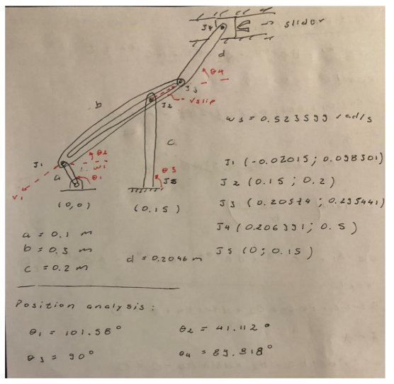
Figure 3: Kinematic analysis part 1

Figure 4: Kinematic analysis part 2

Figure 5: Kinematic analysis part 3

Figure 6: Kinematic analysis part 4

Figure 7: Kinematic analysis part 5

Figure 8: Kinematic analysis part 6
This is a one step solution for an instantaneous configuration of the system. This same principle and equations were applied for a cycle of input angle between 0 and 180 degrees (mainly because of space constrains). The MATLAB code use for this iterative procedure is shown here and the code for the animation (the code is attached to this final submission):
MATLAB code for kinematic analysis:
%Full Kinematic Analysis of Quick Return
% Gabriel Iturralde Duenas
close all
%Define constants
%Note: Constants are changed to allow full rotation
global b_0 A B C D E omega1 alpha1
b_0= 0.1982; A = 0.1; B = 0.3; C= 0.2; D= 0.2046; E=0.5; alpha1=-0.1; omega1 = 0.523599
%Define input vector
theta1 = linspace(deg2rad(0), deg2rad(180), 100);
%Empty vectors
P = zeros(1,100);
Pdot = zeros(1,100);
Pddot = zeros(1,100);
%plot in degrees
theta2_deg = linspace(0,180,100);
for i = 1:100
%find values of theta at current config through pos analysis
[theta2,theta4,bd_0] = posAnalysis(theta1(i));
P(i) = bd_0;
%find the velocity of the slider
[omega2,omega4, bdot] = velAnalysis(theta1(i),theta2,theta4,bd_0);
P_dot(i) = bdot;
%find the acceleration of the slider
[b_ddot alpha2 alpha4] = accAnalysis(theta1(i),theta2,theta4,omega2,omega4,bdot)
P_ddot(i) = b_ddot;
%plot
origin = [0; 0];
input = [0.15; 0];
L_A = [Acos(theta1(i)); Asin(theta1(i))];
L_B = L_A + [Bcos(theta2); Bsin(theta2)];
L_C = L_A + [bd_0cos(theta2); bd_0sin(theta2)]
L_E = [L_B(1)+Dcos(theta4); 0.5];*
figure(1)
plot(origin(1),origin(2),’ro’,’linewidth’,3)
hold on
plot(input(1),input(2),’ro’,’linewidth’,3)
plot(L_A(1),L_A(2),’ro’,’linewidth’,3)
plot(L_B(1),L_B(2),’ro’,’linewidth’,3)
plot(L_C(1),L_C(2),’ro’,’linewidth’,3)
plot(L_D(1),L_D(2),’ro’,’linewidth’,3)
plot(L_E(1),L_E(2),’ro’,’linewidth’,3)
line([origin(1) L_A(1)], [origin(2) L_A(2)],’linewidth’,3)
line([input(1) L_C(1)], [input(2) L_C(2)],’linewidth’,3)
line([L_A(1) L_B(1)], [L_A(2) L_B(2)],’linewidth’,3)
line([L_B(1) L_E(1)], [L_B(2) L_E(2)],’linewidth’,3)
title(‘Wheelchair robotic arm’,’fontsize’,15)
xlabel(‘x’,’fontsize’,15)
ylabel(‘y’,’fontsize’,15)
axis ([-0.2 2 0 0.8]); %equal
pause(0.05)
hold off
end
figure
hold on
%plot position
subplot(3,1,1)
plot(theta2_deg,P, ‘Linewidth’, 2)
title(‘Variations in B, Bdot, and Bddot’)
xlabel(‘\theta_2’)
ylabel(“B(theta2)”)
hold off
grid on
%plot velocity
subplot(3,1,2)
plot(theta2_deg,P_dot, ‘r’, ‘Linewidth’, 2)
xlabel(‘\theta_2’)
ylabel(“Bdot(theta2)”)
grid on
hold off
subplot(3,1,3)
plot(theta2_deg,P_ddot,’b’,’Linewidth’,2)
xlabel(‘\theta_2’)
ylabel(“Bddot(theta2)”)
grid on
hold off
function [theta2, theta4,bd_0] = posAnalysis(theta1)
global A B C D E b_0
theta2 = asin(C + Asin(theta1)/b_0);*
theta4 = asin((E -Asin(theta1) — b_0sin(theta2))/D);
bd_0 = sqrt((0.2-Asin(theta1))²+(0.15-Acos(theta1))²);
end
function [omega2,omega4, bdot] = velAnalysis(theta1,theta2,theta4,bd_0)
global A B D omega1
%solve for omega3
A1 = [cos(theta2) -bd_0sin(theta2); -sin(theta2) bd_0cos(theta2)];
B1 = [Aomega1sin(theta1); -Aomega1cos(theta1)];
C1 = A1\B1;
bdot = C1(1);
omega2 = C1(2);
omega4 = (-Aomega1sin(theta1)-bdotcos(theta2)-Bomega2sin(theta2))/(Dsin(theta4));
end
function [b_ddot alpha2 alpha4] = accAnalysis(theta1,theta2,theta4,omega2,omega4,b_dot)
global A B D omega1 alpha1
A2 = [cos(theta2) Bsin(theta2); sin(theta2) -Bcos(theta2)];
B2 = [-alpha1Asin(theta1)-omega1²Acos(theta1)-omega2b_dotsin(theta2)-omega2²Bcos(theta2); alpha1Acos(theta1)- omega1²Asin(theta1)-omega2b_dotcos(theta2)-omega2Bsin(theta2)];
C2 = A2\B2;
b_ddot = C2(1);
alpha2 = C2(2);
alpha4= (Aomega1²cos(theta1)-b_ddotcos(theta2)+b_dotomega2sin(theta2)-Bomega2cos(theta2)-Domega4²cos(theta4))/(Dsin(theta4));
end

Figure 8: Snapshot of the animation of Kinematic Analysis of the 5-bar slotted horizontal slider mechanism
Furthermore, the position, angular velocity and angular acceleration for the slotted bar prismatic and revolute link are shown in Figure 9:

Figure 9: position, angular velocity, and angular acceleration for the slotted bar prismatic and revolute link vs input link angle
As it can be observed, the 3 graphs show are smooth behavior which is desirable for the purpose of this project. In reaching task, is desired to have smooth trajectories that is a biomechanical natural mechanism to plan, execute and control human motor movement (normally the cost function of this optimal solution is the jerk of the trajectory of the arm). However, this is just the slotted bar (link 3) that is not the main target to look for a smooth solution.
Furthermore, the same analysis and graph was obtained for the horizontal slider. Figure 10 shows how the position, linear velocity, and linear acceleration changes for the slider in the 5-bar slotted slider mechanism:

Figure 10: horizontal position, linear velocity, and linear acceleration for the slider vs input link angle
As it can be observed, in Figure 10 the position, linear velocity and linear acceleration of the slider shows smooth curves and an interesting symmetric effect that might accelerates at some part of the trajectory and then decelerates at different points of the trajectory. This might be beneficial for practical applications of the robotic arm when sometimes you need more speed and others more precision.
Here is the MATLAB code for extracting data from the KPMG tool:
%% JOINT ASSEMBLY
a= 0.1;
b= 0.3;
c= sqrt((0.2–0.162)² + (0.5–0.299)²);
c=0.2046;
filename = ‘Design1a.csv’;
T = readtable(filename);
A = table2array(T);
figure(1);
grid on
hold on
plot(rad2deg(A(:,4)),A(:,1),’o’)
xlabel(‘Theta_2 [deg]’)
ylabel(‘Slider position [m]’)
hold off
figure(2);
grid on
hold on
plot(rad2deg(A(:,4)),A(:,2),’o’)
xlabel(‘Theta_2 [deg]’)
ylabel(‘Slider velocity [m/s]’)
hold off
figure(3);
grid on
hold on
plot(rad2deg(A(:,4)),A(:,3),’o’)
xlabel(‘Theta_2 [deg]’)
ylabel(‘Slider acceleration [m/s²]’)
hold off
- Manufacturing and Assembly:
The manufacturing of each of the links, joints, pins, and the gripper’s components were designed using Solidworks and then were 3D printed using the Craftware software and the specifications of the 3D printers at TIW. The material selected for printing the parts of the mechanism was PETG which has higher strength, temperature tolerance and it is better for outdoor use. These properties fit better the design specifications of the robotic wheelchair arm. Furthermore, the torque specifications for the motor were obtained based on force analysis using Newton-Euler derivation for the motor torque and speed. A 12 V DC motor of 0.2 Nm with a maximum speed rate of 500 rpm based on availability and price constrains. This motor was selected for powering the input link because the size of the links is big enough and it was desirable to have a considerable horizontal speed of the slider. Moreover, the motor for actuating the gripper is a small 6–12 V DC motor that can open or close for grasping objects. Based on force analysis the torque needed for the gripper was 0.1 Nm to have enough power to handle standard and common objects used for activities of daily living (ADL).
The mechanism was entirely design using the kinematic analysis presented in the previous section and all the power and stress analysis described above. Moreover, the gripper fingers and mechanism were modified based on an original project that is available online in Grabcad (Steiner, 2020) since its design was not the main target of the project and was an extra feature of the system. Important specifications like size, number of teeth of the gears and gear ratio were modified to increase the power of the gripper fingers while decreasing the motor input speed.
One schematic of each one of the processes are shown in Figure 8.


Figure 8: Steps 1–3 in manufacturing process
- Assembly:
The assembly process consisted in mainly establishing the appropriate coordination between the links, the slider, the joints, the grounds (attachments mounted to the wheelchair), the gripper and the pins. One main limitation of the design is based on that the pins and joints were designed based on hawing some low friction material (such as wood sticks) and two bearings attached to them. However, the designs and parts were developed and printed previously to the arrival of supplements and materials that arrive to the IDEA lab. Figure 9 shows an schematic of how the final mechanism was assembled. The idea behind the ground designs was that they can be easily mounted on any standard wheelchair.

Figure 9: Schematic of the mechanism assembly
List of links:
- Link 1 (grounded input)
- Link 2 (slotted bar)
- Link 3
- Link 4 (grounded)
- Link 5 (slider output)
List of joints:
- Joint 1: revolute — ground
- Joint 2: revolute
- Joint 3: revolute-prismatic
- Joint 4: revolute
- Joint 5: revolute-prismatic
Figure 9–12 show how the links, joints, grounds, slider, and gripper were assembled.

Figure 9: Assembly of link 2, link 3 and slidder

Figure 10: Assembly of ground 1, link 1 and link 2

Figure 11: Assemble of slider, griper and griper’s fingers

Figure 12: Assemble of ground 2, link 2 and link 4
- Electronics and software:
The electronics and software were developed using a MATLAB app using MATLAB app designer and the Arduino app for MATLAB in which the main functions of the motor input control were defined. The basic functions of this app were to modify the direction of rotation of the input link (clockwise or counterclockwise), the motor angular speed and the motor angular acceleration (this was programmed in the controller using increments or decrements in the motor angular speed with respect to time). The code for the MATLAB app is presented here:
classdef Home_RMD_Proj < matlab.apps.AppBase
% Properties that correspond to app components
properties (Access = public)
UIFigure matlab.ui.Figure
EditField_2 matlab.ui.control.NumericEditField
EditField_2Label matlab.ui.control.Label
Image3 matlab.ui.control.Image
Image2 matlab.ui.control.Image
AngvelocityrpmEditField matlab.ui.control.NumericEditField
AngvelocityrpmEditFieldLabel matlab.ui.control.Label
UpButton matlab.ui.control.Button
DownButton matlab.ui.control.Button
EditField matlab.ui.control.EditField
Image matlab.ui.control.Image
end
methods (Access = public)
end
properties (Access = private)
ang_vel;
ang_acc;
end
% Callbacks that handle component events
methods (Access = private)
% Callback function
function S2ButtonPushed(app, event)
end
% Button pushed function: UpButton
function UpButtonPushed(app, event)
a = arduino(‘COM4’,’Uno’); % define the Arduino Communication port
configurePin(a,’D10',’PWM’);
configurePin(a,’D5',’DigitalOutput’);
configurePin(a,’D6',’DigitalOutput’);
writeDigitalPin(a,’D5',1);
writeDigitalPin(a,’D6',0);
writePWMVoltage(a,’D10',(150*5)/200);
end
% Button pushed function: DownButton
function DownButtonPushed(app, event)
a = arduino(‘COM4’,’Uno’);
configurePin(a,’D10',’PWM’);
configurePin(a,’D5',’DigitalOutput’);
configurePin(a,’D6',’DigitalOutput’);
writeDigitalPin(a,’D5',1);
writeDigitalPin(a,’D6',0);
writePWMVoltage(a,’D10',(150*5)/200);
end
% Value changed function: AngvelocityrpmEditField
function AngvelocityrpmEditFieldValueChanged(app, event)
app.ang_vel = app.AngvelocityrpmEditField.Value;
end
% Callback function
function AngaccelerationEditFieldValueChanged(app, event)
app.ang_acc = app.AngaccelerationEditField.Value;
end
end
% Component initialization
methods (Access = private)
% Create UIFigure and components
function createComponents(app)
% Create UIFigure and hide until all components are created
app.UIFigure = uifigure(‘Visible’, ‘off’);
app.UIFigure.Color = [0.2392 0.2314 0.2392];
app.UIFigure.Colormap = [0.949 0.4902 0.0588;0.949 0.4902 0.0588;0.949 0.4902 0.0588;0.949 0.4902 0.0588;0.251 0.1608 0.7098;0.251 0.1686 0.7176;0.2549 0.1725 0.7294;0.2549 0.1765 0.7412;0.2588 0.1804 0.749;0.2588 0.1843 0.7608;0.2588 0.1882 0.7686;0.2627 0.1961 0.7922;0.2667 0.2 0.8039;0.2667 0.2039 0.8157;0.2706 0.2078 0.8235;0.2706 0.2157 0.8353;0.2706 0.2196 0.8431;0.2745 0.2235 0.851;0.2745 0.2275 0.8627;0.2745 0.2314 0.8706;0.2745 0.2392 0.8784;0.2784 0.2431 0.8824;0.2784 0.2471 0.8902;0.2784 0.2549 0.898;0.2784 0.2588 0.902;0.2784 0.2667 0.9098;0.2784 0.2706 0.9137;0.2784 0.2745 0.9216;0.2824 0.2824 0.9255;0.2824 0.2863 0.9294;0.2824 0.2941 0.9333;0.2824 0.298 0.9412;0.2824 0.3059 0.9451;0.2824 0.3098 0.949;0.2824 0.3137 0.9529;0.2824 0.3216 0.9569;0.2824 0.3255 0.9608;0.2824 0.3294 0.9647;0.2784 0.3373 0.9686;0.2784 0.3412 0.9686;0.2784 0.349 0.9725;0.2784 0.3529 0.9765;0.2784 0.3569 0.9804;0.2784 0.3647 0.9804;0.2745 0.3686 0.9843;0.2745 0.3765 0.9843;0.2745 0.3804 0.9882;0.2706 0.3843 0.9882;0.2706 0.3922 0.9922;0.2667 0.3961 0.9922;0.2627 0.4039 0.9922;0.2627 0.4078 0.9961;0.2588 0.4157 0.9961;0.2549 0.4196 0.9961;0.251 0.4275 0.9961;0.2471 0.4314 1;0.2431 0.4392 1;0.2353 0.4431 1;0.2314 0.451 1;0.2235 0.4549 1;0.2196 0.4627 0.9961;0.2118 0.4667 0.9961;0.2078 0.4745 0.9922;0.2 0.4784 0.9922;0.1961 0.4863 0.9882;0.1922 0.4902 0.9882;0.1882 0.498 0.9843;0.1843 0.502 0.9804;0.1843 0.5098 0.9804;0.1804 0.5137 0.9765;0.1804 0.5176 0.9725;0.1804 0.5255 0.9725;0.1804 0.5294 0.9686;0.1765 0.5333 0.9647;0.1765 0.5412 0.9608;0.1765 0.5451 0.9569;0.1765 0.549 0.9529;0.1765 0.5569 0.949;0.1725 0.5608 0.9451;0.1725 0.5647 0.9412;0.1686 0.5686 0.9373;0.1647 0.5765 0.9333;0.1608 0.5804 0.9294;0.1569 0.5843 0.9255;0.1529 0.5922 0.9216;0.1529 0.5961 0.9176;0.149 0.6 0.9137;0.149 0.6039 0.9098;0.1451 0.6078 0.9098;0.1451 0.6118 0.9059;0.1412 0.6196 0.902;0.1412 0.6235 0.898;0.1373 0.6275 0.898;0.1373 0.6314 0.8941;0.1333 0.6353 0.8941;0.1294 0.6392 0.8902;0.1255 0.6471 0.8902;0.1216 0.651 0.8863;0.1176 0.6549 0.8824;0.1137 0.6588 0.8824;0.1137 0.6627 0.8784;0.1098 0.6667 0.8745;0.1059 0.6706 0.8706;0.102 0.6745 0.8667;0.098 0.6784 0.8627;0.0902 0.6824 0.8549;0.0863 0.6863 0.851;0.0784 0.6902 0.8471;0.0706 0.6941 0.8392;0.0627 0.698 0.8353;0.0549 0.702 0.8314;0.0431 0.702 0.8235;0.0314 0.7059 0.8196;0.0235 0.7098 0.8118;0.0157 0.7137 0.8078;0.0078 0.7176 0.8;0.0039 0.7176 0.7922;0 0.7216 0.7882;0 0.7255 0.7804;0 0.7294 0.7765;0.0039 0.7294 0.7686;0.0078 0.7333 0.7608;0.0157 0.7333 0.7569;0.0235 0.7373 0.749;0.0353 0.7412 0.7412;0.051 0.7412 0.7373;0.0627 0.7451 0.7294;0.0784 0.7451 0.7216;0.0902 0.749 0.7137;0.102 0.7529 0.7098;0.1137 0.7529 0.702;0.1255 0.7569 0.6941;0.1373 0.7569 0.6863;0.1451 0.7608 0.6824;0.1529 0.7608 0.6745;0.1608 0.7647 0.6667;0.1686 0.7647 0.6588;0.1725 0.7686 0.651;0.1804 0.7686 0.6471;0.1843 0.7725 0.6392;0.1922 0.7725 0.6314;0.1961 0.7765 0.6235;0.2 0.7804 0.6157;0.2078 0.7804 0.6078;0.2118 0.7843 0.6;0.2196 0.7843 0.5882;0.2235 0.7882 0.5804;0.2314 0.7882 0.5725;0.2392 0.7922 0.5647;0.251 0.7922 0.5529;0.2588 0.7922 0.5451;0.2706 0.7961 0.5373;0.2824 0.7961 0.5255;0.2941 0.7961 0.5176;0.3059 0.8 0.5059;0.3176 0.8 0.498;0.3294 0.8 0.4863;0.3412 0.8 0.4784;0.3529 0.8 0.4667;0.3686 0.8039 0.4549;0.3804 0.8039 0.4471;0.3922 0.8039 0.4353;0.4039 0.8039 0.4235;0.4196 0.8039 0.4118;0.4314 0.8039 0.4;0.4471 0.8039 0.3922;0.4627 0.8 0.3804;0.4745 0.8 0.3686;0.4902 0.8 0.3569;0.5059 0.8 0.349;0.5176 0.8 0.3373;0.5333 0.7961 0.3255;0.5451 0.7961 0.3176;0.5608 0.7961 0.3059;0.5765 0.7922 0.2941;0.5882 0.7922 0.2824;0.6039 0.7882 0.2745;0.6157 0.7882 0.2627;0.6314 0.7843 0.251;0.6431 0.7843 0.2431;0.6549 0.7804 0.2314;0.6706 0.7804 0.2235;0.6824 0.7765 0.2157;0.698 0.7765 0.2078;0.7098 0.7725 0.2;0.7216 0.7686 0.1922;0.7333 0.7686 0.1843;0.7451 0.7647 0.1765;0.7608 0.7647 0.1725;0.7725 0.7608 0.1647;0.7843 0.7569 0.1608;0.7961 0.7569 0.1569;0.8078 0.7529 0.1529;0.8157 0.749 0.1529;0.8275 0.749 0.1529;0.8392 0.7451 0.1529;0.851 0.7451 0.1569;0.8588 0.7412 0.1569;0.8706 0.7373 0.1608;0.8824 0.7373 0.1647;0.8902 0.7373 0.1686;0.902 0.7333 0.1765;0.9098 0.7333 0.1804;0.9176 0.7294 0.1882;0.9255 0.7294 0.1961;0.9373 0.7294 0.2078;0.9451 0.7294 0.2157;0.9529 0.7294 0.2235;0.9608 0.7294 0.2314;0.9686 0.7294 0.2392;0.9765 0.7294 0.2431;0.9843 0.7333 0.2431;0.9882 0.7373 0.2431;0.9961 0.7412 0.2392;0.9961 0.7451 0.2353;0.9961 0.7529 0.2314;0.9961 0.7569 0.2275;0.9961 0.7608 0.2235;0.9961 0.7686 0.2196;0.9961 0.7725 0.2157;0.9961 0.7804 0.2078;0.9961 0.7843 0.2039;0.9961 0.7922 0.2;0.9922 0.7961 0.1961;0.9922 0.8039 0.1922;0.9922 0.8078 0.1922;0.9882 0.8157 0.1882;0.9843 0.8235 0.1843;0.9843 0.8275 0.1804;0.9804 0.8353 0.1804;0.9765 0.8392 0.1765;0.9765 0.8471 0.1725;0.9725 0.851 0.1686;0.9686 0.8588 0.1647;0.9686 0.8667 0.1647;0.9647 0.8706 0.1608;0.9647 0.8784 0.1569;0.9608 0.8824 0.1569;0.9608 0.8902 0.1529;0.9608 0.898 0.149;0.9608 0.902 0.149;0.9608 0.9098 0.1451;0.9608 0.9137 0.1412;0.9608 0.9216 0.1373;0.9608 0.9255 0.1333;0.9608 0.9333 0.1294;0.9647 0.9373 0.1255;0.9647 0.9451 0.1216;0.9647 0.949 0.1176;0.9686 0.9569 0.1098;0.9686 0.9608 0.1059;0.9725 0.9686 0.102;0.9725 0.9725 0.0941;0.9765 0.9765 0.0863;0.9765 0.9843 0.0824];
app.UIFigure.Position = [100 100 640 480];
app.UIFigure.Name = ‘MATLAB App’;
% Create Image
app.Image = uiimage(app.UIFigure);
app.Image.Position = [1 359 133 122];
app.Image.ImageSource = ‘NEURO BIONIKS_Mesa de trabajo 1 copia 4.png’;
% Create EditField
app.EditField = uieditfield(app.UIFigure, ‘text’);
app.EditField.HorizontalAlignment = ‘center’;
app.EditField.FontName = ‘Calibri’;
app.EditField.FontSize = 22;
app.EditField.FontWeight = ‘bold’;
app.EditField.FontColor = [1 1 1];
app.EditField.BackgroundColor = [0.2392 0.2392 0.2314];
app.EditField.Position = [166 381 335 66];
app.EditField.Value = ‘Main menu’;
% Create DownButton
app.DownButton = uibutton(app.UIFigure, ‘push’);
app.DownButton.ButtonPushedFcn = createCallbackFcn(app, @DownButtonPushed, true);
app.DownButton.BackgroundColor = [0.2392 0.2314 0.2314];
app.DownButton.FontName = ‘Calibri’;
app.DownButton.FontSize = 22;
app.DownButton.FontWeight = ‘bold’;
app.DownButton.FontColor = [1 1 1];
app.DownButton.Position = [280 32 164 133];
app.DownButton.Text = ‘Down’;
% Create UpButton
app.UpButton = uibutton(app.UIFigure, ‘push’);
app.UpButton.ButtonPushedFcn = createCallbackFcn(app, @UpButtonPushed, true);
app.UpButton.BackgroundColor = [0.2392 0.2314 0.2392];
app.UpButton.FontName = ‘Calibri’;
app.UpButton.FontSize = 22;
app.UpButton.FontWeight = ‘bold’;
app.UpButton.FontColor = [1 1 1];
app.UpButton.Position = [272 200 163 167];
app.UpButton.Text = ‘Up’;
% Create AngvelocityrpmEditFieldLabel
app.AngvelocityrpmEditFieldLabel = uilabel(app.UIFigure);
app.AngvelocityrpmEditFieldLabel.HorizontalAlignment = ‘right’;
app.AngvelocityrpmEditFieldLabel.FontName = ‘Calibri’;
app.AngvelocityrpmEditFieldLabel.FontSize = 22;
app.AngvelocityrpmEditFieldLabel.FontColor = [1 1 1];
app.AngvelocityrpmEditFieldLabel.Position = [1 200 175 40];
app.AngvelocityrpmEditFieldLabel.Text = ‘Ang. velocity (rpm)’;
% Create AngvelocityrpmEditField
app.AngvelocityrpmEditField = uieditfield(app.UIFigure, ‘numeric’);
app.AngvelocityrpmEditField.ValueChangedFcn = createCallbackFcn(app, @AngvelocityrpmEditFieldValueChanged, true);
app.AngvelocityrpmEditField.FontName = ‘Calibri’;
app.AngvelocityrpmEditField.FontSize = 22;
app.AngvelocityrpmEditField.FontWeight = ‘bold’;
app.AngvelocityrpmEditField.FontColor = [1 1 1];
app.AngvelocityrpmEditField.BackgroundColor = [0.2392 0.2314 0.2392];
app.AngvelocityrpmEditField.Position = [191 209 61 39];
% Create Image2
app.Image2 = uiimage(app.UIFigure);
app.Image2.Position = [313 270 77 112];
app.Image2.ImageSource = ‘Button_up.PNG’;
% Create Image3
app.Image3 = uiimage(app.UIFigure);
app.Image3.Position = [333 0 57 118];
app.Image3.ImageSource = ‘Button_down.PNG’;
% Create EditField_2Label
app.EditField_2Label = uilabel(app.UIFigure);
app.EditField_2Label.HorizontalAlignment = ‘right’;
app.EditField_2Label.Position = [664 117 56 22];
app.EditField_2Label.Text = ‘Edit Field’;
% Create EditField_2
app.EditField_2 = uieditfield(app.UIFigure, ‘numeric’);
app.EditField_2.Position = [735 117 100 22];
% Show the figure after all components are created
end

Figure 11 shows the MATLAB app final GUI and a video of how it is operated is attached to this project folder

Figure 12: MATLAB app GUI for controlling the Elegoo R3 Uno and the input link motor
Furthermore, the electronics used in this project were an Elegoo R3 Uno microprocessor that was directly connected by USB port to the MATLAB app, the 12V DC motor of 300 rpm and 0.2 Nm, a 12 V Ni-MH set of 10 AA rechargeable battery, a L298N motor shield for Arduino Uno. The schematic of the electronics used in this system is shown in Figure 12. Here the push button and the potentiometer functions were replaced with the MATLAB app:

Figure 13: Schematic of the electronics for this system (Retrieved from Arduino tutorials)
The final electronic setup is shown in Figure 13 on which, the PC where the MATLAB app was designed, the Elegoo Uno microcontroller, the 12V DC motor and the L298N are presented.
An alternative Elegoo Uno was developed using Arduino IDE to test the basic functions of the motor controller. The code use is shown here:
int motorPin = 3;
const int pwm = 10;
const int ford = 5;
const int back = 6;
void setup() {
// put your setup code here, to run once:
pinMode(motorPin, OUTPUT);
pinMode(pwm,OUTPUT);
pinMode(ford,OUTPUT);
pinMode(back,OUTPUT);
digitalWrite(ford,HIGH);
digitalWrite(back,LOW);
}
void loop() {
// put your main code here, to run repeatedly:
delay(3000);
digitalWrite(ford,HIGH);
digitalWrite(back,LOW);
analogWrite(pwm,150);
delay(1000);
delay(3000);
delay(3000);
digitalWrite(ford,HIGH);
digitalWrite(back,LOW);
analogWrite(pwm,150);
}
- Final prototype:
The final prototype is shown in Figure 14–18. The videos that show the final prototype mechanism and the electronics setup are attached in the folder of the final report. Because of time constrains it was not possible to attach the input motor to input link efficiently, but this can be easily accomplished for future work. The gripper motor was also not included in the final mechanism prototype due to time constrain, however the controller and electronics were ready for its setup.

Figure 14: Final assemble- side view

Figure 15: side view of final prototype

Figure 16: front view of the robotic wheelchair arm

Figure 17: side view of the final prototype

Figure 17: final view of the prototype

Figure 18: Design of the electronics setup of the final prototype
- Conclusions and future work:
Therefore, the main objective of this project was to to develop a 1 DOF (that is compatible for a 2 DOF modular extension) robotic mounted wheelchair arm that can help patients with motor low to moderate disabilities and low cognitive impairment to perform some ADL reaching tasks in an affordable and portable manner using a 5-bar slotted slider mechanism with a two fingered gripper. For that, some important design specifications such as having a smooth trajectory for the slider with respect to the input angle of the mechanism played a key role because it is well-known that this is naturally the way that the human body performed most of reaching task in a natural manner, in terms of engineering, by optimizing the jerk of the trajectory. This was successfully accomplished with the design and kinematic analysis. However, the final prototype had limitations on having a smooth motion and coordination between the links mainly because of the friction generated by the 3D printed pins that were designed as an alternative because the original design did not account for the size of the available pins (wood sticks and bearings). There were several strategies to reduce friction between links and joint that mainly were using lubricant products in all the joints and links and polishing all the links, joints and pins surface made of PETG. Another main limitation of the prototype was that link 4 that is the one attached to ground 2 and connected to link 2 (the slotter bar that has a revolute and prismatic joint) was printed incorrectly for 4 consecutive times by the TIW stuff. This was a problem based on the amount of workload and the printing time of each links that were of big size and had an average printing time of 12 h. Moreover, link 4 has to be reconstructed by cutting similar parts from other links and melting the surfaces and cooling them down in order to at least obtain a similar shape and try as it was possible to do not lose the mechanical properties and design properties that this link was aimed to have. Furthermore, another limitation was based on a printing error that link 2 because of its design and size and had a repeated printing error (in the TIW) that cause the part to break 4 times when it was ready. Finally, extra supports were added to warranty that the part will not have an error while printing and also additional features in the design were added to increase the mechanical safety after solidworks stress analysis. Mainly the added features were fillets and rounded surfaces to decrease any stress concentration. However, the original design had 3 safety factor under typical maximum operating conditions.
The electronics and software were developed using the MATLAB app designer to control via an app the motor speed, direction and angular acceleration using an Elegooo R3 Uno microcontroller, a 12V DC motor, a 12V Ni-MH 10 AA battery package (that was easily mounted and portable) and a L298N. The electronics were ready to be implemented in the input link as well as in the fingered gripper but due to time constrains it was not possible to accomplish that goal.
Therefore, the main objectives of this project and the design specifications and aims were accomplished in the design process and a considerable part of them by the final prototype. For future work, link 4 has to be properly printed and assembled to the mechanism, reducing a lot of friction and limitation of the mechanism movement. Include a better pin design using wood sticks and bearings in each of the links and though the implementation of the motor and electronics to the input link and to the 2 fingered griper. Additionally, a modular design of the grounds that can be electronically actuated can be added to increase or decrease the vertical position of the slider. This will provide an additional degree of freedom to the mechanism in a easy and affordable manner.
- References:
-
Sulzer, J. S., Peshkin, M. A., & Patton, J. L. (2007, June). Design of a mobile, inexpensive device for upper extremity rehabilitation at home. In 2007 IEEE 10th International Conference on Rehabilitation Robotics (pp. 933–937). IEEE.
-
Voznenko, T. I., Chepin, E. V., & Urvanov, G. A. (2018). The control system based on extended bci for a robotic wheelchair. Procedia computer science, 123, 522–527.
-
Bailey, M., Chanler, A., Maxwell, B., Micire, M., Tsui, K., & Yanco, H. (2007, June). Development of vision-based navigation for a robotic wheelchair. In 2007 IEEE 10th International Conference on Rehabilitation Robotics (pp. 951–957). IEEE.
-
Díaz, I., Gil, J. J., & Sánchez, E. (2011). Lower-limb robotic rehabilitation: literature review and challenges. Journal of Robotics, 2011.
-
Volosyak, I., Ivlev, O., & Graser, A. (2005, June). Rehabilitation robot FRIEND II-the general concept and current implementation. In 9th International Conference on Rehabilitation Robotics, 2005. ICORR 2005. (pp. 540–544). IEEE.
-
Bastos-Filho, T. F., Cheein, F. A., Müller, S. M. T., Celeste, W. C., de la Cruz, C., Cavalieri, D. C., … & Carelli, R. (2013). Towards a new modality-independent interface for a robotic wheelchair. IEEE Transactions on Neural Systems and Rehabilitation Engineering, 22(3), 567–584.
메타데이터
- post_id
- 48e69ea4c811
- slug
- house-made-wheelchair-robotic-arm-48e69ea4c811
- url
- https://medium.com/kairi-ai/house-made-wheelchair-robotic-arm-48e69ea4c811
- canonical_url
- https://medium.com/kairi-ai/house-made-wheelchair-robotic-arm-48e69ea4c811
- author_url
- https://medium.com/@gabriel.iturra93
- status
- ok
- fetched_at
- 2026-07-20 04:21:39