FlyOver: Part 2
Hello everyone! In this part I will talk about environment mapping, HDR tonemapping, texturing, creating a cosine wave water plane, reading…
FlyOver: Part 2
Hello everyone! In this part I will talk about environment mapping, HDR tonemapping, texturing, creating a cosine wave water plane, reading 3D meshes and a proper third person orbiting camera. This will build upon the previous blog post where I talked about terrain generation and rendering using b-splines, and quaternion cameras. I briefly mentioned at the start of the previous blog post that the second homework of the course this series is a part of might be a continuation of the first one, and as you can see it turned out to be just that.
I don’t know yet if the next homework will be on the same topic, but even this foundation feels strong so I’ll perhaps build upon this even after the end of the term. Nevertheless I wanted to give this project an overall name so it stays coherent when I further add new features. The name I came up with is FlyOver, because we fly over a generated terrain following a plane model. I will also talk about some new cool features that could be added to the project that would make it even cooler and perhaps take it to the next level.
The previous part of this project is already public. You can find this public version of the code on my GitHub profile in a couple of weeks: https://github.com/distortedfuzz.

FlyOver Image
HDR and Tonemapping
I have previously implemented this stuff as part of the Advanced Ray Tracer project. You can check out a more thorough explanation in part 5 of that project if you want. Here, I will focus on the real-time OpenGL side of HDR rendering.
HDR Framebuffer
Generic, also called LDR rendering has a problem where every color value must be in the range [0, 1]. This creates a problem in the sense that we lose a lot of the color data which makes a huge visual difference. To keep all the juice in the images, we first render the image without limiting everything to the [0, 1] range. After rendering the whole scene like that pixel by pixel, we then apply tonemapping, where we map every color value so that all the differences are visible, and we can properly see the relative color changes.
To keep the initially rendered color values, we create a framebuffer (FBO) of the same size of the window. In this framebuffer, I used a 16-bit floating point texture as its color attachment, which can store values well beyond the tiny [0, 1] range. All rendering we do initially goes into this texture instead of directly rendering to the screen. The fourth channel of this kind of texture or color (alpha) is normally used for transparency, but in this case, we use it to store the log luminance of each separate pixel. Each fragment shader writes this value explicitly each time it’s called like:
float luminance = dot(color.rgb, vec3(0.2126, 0.7152, 0.0722));
frag_color = vec4(color.rgb, log(luminance + 0.00001));
This is the commonly used luminance formula. It is the formula that converts RGB colors to a single value which represents perceived brightness. The formula takes into consideration the human eyes and their sensitivity to different colors. As you can see, the green channel has the most weight and blue the least. This is because the cones in our eyes that observe the color green are the most numerous, and blue is the least.
We also need the average luminance of the whole scene for later tonemapping. This is where mipmaps come in. They are progressively halved versions of a texture, and we can halve the texture up until 1x1. An example continuation could look like this: 1000x800, 500x400, 250x200, 125x100 ….. 1x1. In OpenGL, these are generated using glGenerateMipmap, it does this halving and averages the values from the level above. So at the end the final 1x1 mip level contains the average log luminance of every pixel. This gives us the mean luminance value we will use.
HDR Environment Map
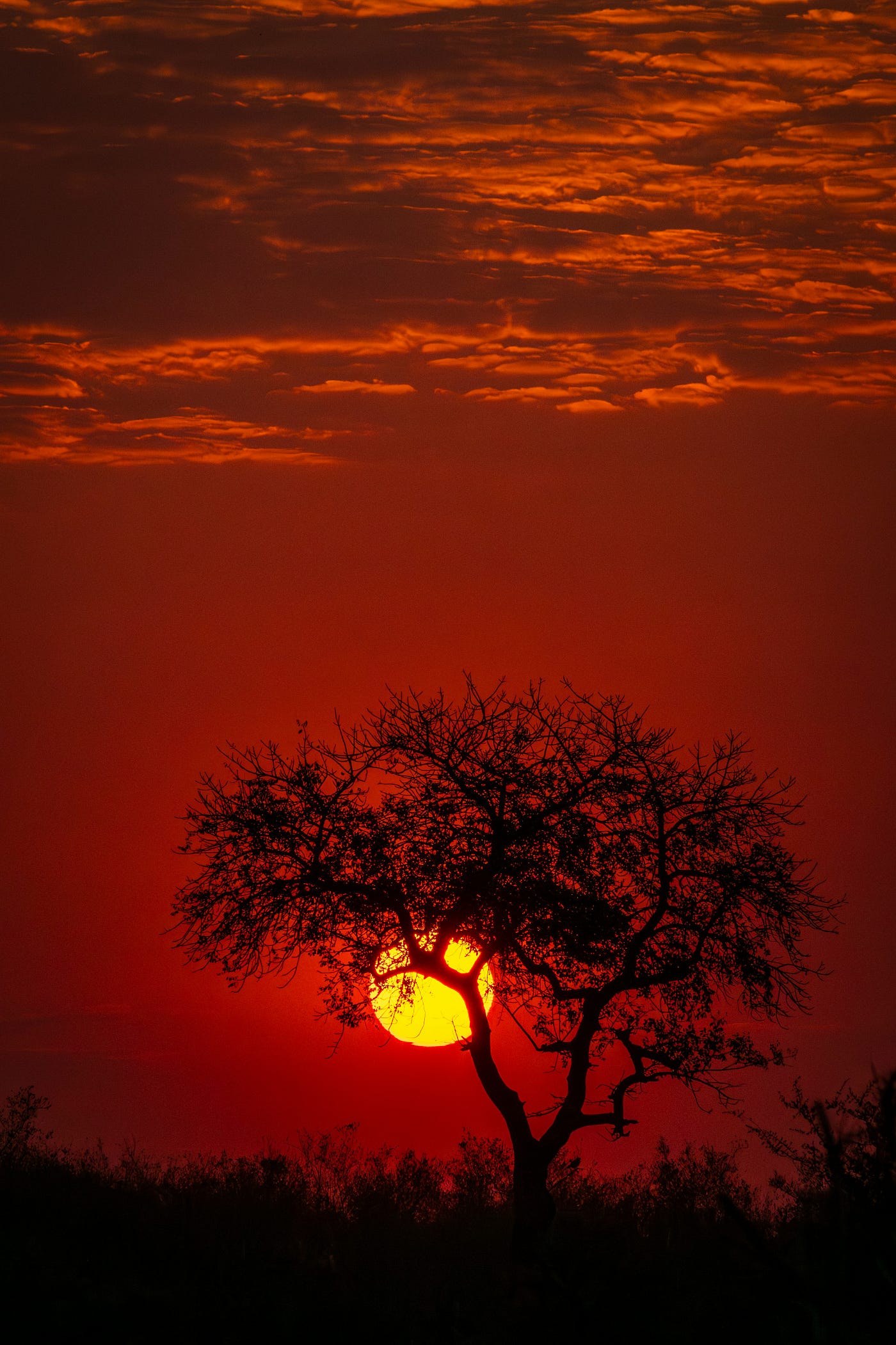
An environment map is a spherical panoramic image that spans the whole space. Everywhere we look we should basically see the environment map. As you might guess, these are usually sky images that cover especially the entire upper hemisphere. Again, these are spherical panoramic images, and equirectangular projection is used to map them into 2D properly, a concept I talked about in the previous part.
We need to read these images in some way different than normal images, as they are not just 8-bit integers in the range [0, 255]. This project uses stb_image to read these HDR texture images. The stbi_loadf function just handles this and we can store everything as a GL_RGB16F texture.
So let’s say we load one of these images, and want to render them all over the scene. To do that, we create a quad which covers the entire screen in NDC space. In the fragment shader of this environment map quad, we reconstruct the world space view direction by multiplying through inverse projection and inverse view matrices for each pixel, and we sample the HDR environment map with these directions. We put this quad at the very back of everything, so it doesn’t cover any object, but acts as the environment.
Another critical issue here is that we have to sample the environment map texture by using these directions. We do this by using the formula:
float u = atan(direction.z, direction.x) / (2.0 * PI) + 0.5;
float v = asin(clamp(direction.y, -1.0, 1.0)) / PI + 0.5;
These are just generic spherical coordinates, the atan part forms the longitude and asin the latitude. There are a ton of resources on the math behind this formula, and it’s quite easy to grasp. I talked about it more in detail again in part 5 of the Advanced Ray Tracer project I believe, you can look into that.
At this point we have an environment map that we can see as the environment from the camera, also if we wanted to use the environment map for the rendering of some other object, we can just use this environment map sampling method to get the environment color of the reflection or normal directions.
Reinhard Tonemapping Operator
The steps of Reinhard tonemapping are these 4: luminance mapping, sigmoidal compression (the core Reinhard operator), burnout and gamma correction. Gamma correction might actually not be considered as a part of Reinhard tonemapping, but it is nonetheless a part of the full tonemapping pipeline. I will explain each part separately, provide the code snippets, and also explain why they’re important to the pipeline.
Luminance Mapping: First, we want to scale the HDR color values so that the average brightness of the scene lands at a perceptually neutral middle grey (Advanced Ray Tracer: Part 5 for further explanation). This scales down the bright scenes and scales up the dark ones. This is like an initial mapping of any scene to an acceptable starting point.
float avg_luminance = clamp(exp(textureLod(hdr_map, uv_coords, 10000.0).a), 0.1, 2.0);
float exposure = 1.0 / (avg_luminance + 0.00001);
color_val = color_val * exposure;
The middle grey value is actually 0.18, but I didn’t quite like the image that value produced. It made everything look a little dark for my liking, maybe that’s because the environment map is a little too grey. So I changed that value until I liked it. I could’ve used ImGUI to change this middle grey value interactively, but that seemed like too much work, so I didn’t.
Reinhard Operator (Sigmoidal Compression): Second, we map everything to the [0, 1) range using sigmoidal compression. This mainly helps that dark values don’t change much, middle values change slightly, but very bright values get compressed, but still pushed toward white. This also ensures that every color value gets a unique output.
color_val = color_val / (color_val + vec3(1.0));
Sigmoidal Compression (Reinhard TMO) from CENG469 Course Notes (Akyuz, 2025–2026)
Burnout: Third, we can apply burnout above a certain luminance value. Burnout refers to allowing the brightest highlights to clip to pure white. We can add this for artistic effect, but it doesn’t have much practicality for our use. I also didn’t add it in this part, but here’s the formula:

Burnout Formula from CENG469 Course Notes (Akyuz, 2025–2026)
Gamma Correction: This is the last step. The issue this step solves is that monitors do not display light linearly, instead they apply a power curve to input values. Gamma correction basically compensates for that later power curve by applying the inverse curve beforehand. This makes the final image look correct on the screen when we actually see it.
color_val = pow(color_val, vec3(1.0/2.2));After completing all these steps, we can see a nice environment map by drawing the environment quad:

HDR Environment Map Image 1

HDR Environment Map Image 2
Texturing
Terrain Textures
As you might remember from part 1, I used different colors for each height range. In this part we have something way better, we have 4 textures to properly visualize all different height values: shore, grass, rock and snow. The important thing here is that the texture is tiny compared to the terrain. So we need to properly tile the texture on it. For this we need to read the texture with the setting GL_REPEAT, so when we read the texture with a larger value than 1, it repeats itself. But we also need to properly set up repeating coordinates in the fragment shader. We can just do this by multiplying the current uv coordinate of that point by a larger constant. This can be the same for all of the terrain. I decided to make this tiling constant 50, which visibly repeats itself, but not that much stretching is seen.
Texture Mixing
In the previous part the different color mixed smoothly near layer change heights. In this case, we can again sample the current layer’s and the next layer’s textures, and then mix these two color values by weighing using height linear interpolation. I used the mix() function for the shore-grass and grass-rock transitions after using linear interpolation weight values. For the rock-snow transition I used smoothstep() to find the mixing weight so that the snow texture doesn’t dominate the larger heights.
This produced great looking results:

Textured Terrain Image 1

Textured Terrain Image 2
As you can see we can clearly see the same texture tiling over and over again when we see the full terrain. Also you can see that the side that’s looking at the direction of the sun is brighter, and the other side is just in front of some clouds so it is visibly darker. That’s because in the shading step, I used the current point’s normal to sample the environment map for more realism.
Water Plane
Generating the Plane Mesh
The water plane is just a flat plane that exists at a certain height at first. This is extremely easy to create as I implemented tesselation in the previous part. There, I sampled splines to later create a terrain mesh, here the job is way easier. I just create a plane using a function that takes the 4 corners, the plane normal and the vertical and horizontal resolutions as input. Then we can just uniformly sample in between these points row by row and triangulate to form the mesh. After this we do the OpenGL array/buffer creation and upload steps and we’re done.
Cosine Waves
At this point we only have a flat mesh, but we want waves on our seas. We can see effects like these in a few ways. The most apparent could be changing the vertex positions using vertex shaders by using a trigonometric wave like cosine with a time parameter. This is the same as seeing a cosine wave on a plane instead of the 2D coordinate system.
Here, we can merge more than one cosine wave with different magnitudes, offsets and periods. By combining with different settings we can get more intriguing waves. Another thing to consider is that Y is the upper direction, whereas X and Z are the actual directions our water plane resides on. Instead of making the cosine waves move on just one direction, we can make them change with respect to both X and Z and have diagonal waves on the water plane. I tried a lot of different combinations here, and saw that when there are many waves, and also waves with small periods, the water looks tiled from certain angles. Because of that I decided to go with larger and more sparse waves by combining three cosine waves:
    float w = 0.0;
    w += 2000.0 * cos(0.00007 * position.x + time * 1.5);
    w += 1500.0 * cos(0.00009 * position.z + time * 0.9);
    w += 1000.0  * cos(0.00012 * (position.x + position.z) + time * 2.3);
    return w;
Normal Calculation
At this point the vertex coordinates change, but we also need to change the normals so that shading looks on point. I used the finite difference method here. We just get the height value of the current position, and the height value at a slightly x-offset height and a slightly z-offset height. Then we use these 3 new 3D coordinates to extract 2 tangent vectors and take the cross product to get the normal. We then reflect the viewing direction using this normal and sample the HDR environment map using this reflection vector. This is an extremely simple and intuitive method which gives good results.
Here are the sea and terrain meshes combined:

Waves and Terrain Image
As you can see, the environment map is also sampled similar to the terrain for shading, which gives us nice looking reflections.
Plane Model
Combining the Plane Model Components
The given plane model has 4 separate meshes to be combined: body, propeller, cables and cockpit. These are given as .obj files which are easy to parse so I’ll just pass that part. Three of these (propeller, cables and cockpit) require transformations to align to the body mesh. This is normal with most models as they are usually modeled separately and then combined into one. If you know the adequate transformation that lines up the parts, you can just pass that as the modeling matrix to the vertex shader, which is easy and what I did. But this will require some more work when the plane moves, and when we rotate the propeller. Another thing to note is the 3 plane parts propeller, cables and body use the same vertex and fragment shaders as they’re really straight forward, but the cockpit has separate ones as it needs careful attention about reflection.
Propeller Rotation Animation
This is relatively simple as we just rotate the propeller around its local Z direction before the other plane alignment and movement transformations. This is easily done by calculating a rotation angle based on time, and applying that. Here’s the propeller modeling transformation code:
propeller_angle += delta_time * 700.0f;
glm::mat4 propeller_rot_transform = propeller_transformation
                           * glm::rotate(glm::mat4(1.0f),
                   glm::radians(propeller_angle), glm::vec3(0.0f, 0.0f, 1.0f));
plane_shader.set_uniform("model", plane_world * propeller_rot_transform);
Cockpit Reflection
All 3 meshes other than the cockpit have textures and are straightforward. But the cockpit doesn’t have a texture, it needs to properly reflect the HDR environment map making it look like a shiny glass surface. This uses a similar technique to the water. The viewing direction from the camera to the cockpit point is reflected against the surface normal, and we just sample the HDR map with the resulting reflection direction.

Plane Model Image 1

Plane Model Image 2

Plane Model Image 3
As you can see the plane body is shaded with the environment map, which creates some nice visuals. Observing the reflection of the cockpit is harder, as it is smaller and wide, but I rotated to show how it looks:

Plane Cockpit Image
Orbiting Camera and Controls
Third Person Plane Camera
In the previous part, we controlled the camera. In this part, we mainly apply the same quaternion movements to the plane and follow it from a third person camera. The big difference is that the plane doesn’t have lateral movement like the previous camera. Other than that, we apply the exact same quaternion transformations to the plane position and orientation, then find the full transformation for all its vertices. While this happens, we need the camera to follow the plane from a distance.
Orbiting and Zooming
I use spherical coordinates to position the camera around the plane, basically using two orbit angles: orbit yaw and pitch. This defines the direction vector of the camera with respect to the plane, which gives us the camera’s orientation. There’s also a camera distance value I hold. When we scale this direction vector by the camera distance and transform it into world space using the plane’s orientation, we get the camera’s world position by adding it to the plane’s position.
The camera orbits around the plane by holding the right mouse button (RMB) and simultaneously moving the mouse. We can also zoom in and out to the plane by using the scroll wheel. This operation has some bounds that limits the camera getting too close to or too far from the plane.
The New Plane Flight Controls
The plane controls are extremely similar to the previous camera controls. Q and E apply yaw rotation which is exactly the same. W and S increase and decrease the plane’s forward speed instead of changing its absolute coordinates like before. Pressing the left alt and the left mouse buttons at the same time (LeftAlt + M1) while moving the mouse applies pitch and yaw with that single operation. There’s no roll here right now, which would be unrealistic for an actual flight simulation or game, but for this case it seems enough and makes things simpler.

FlyOver Image 2
Conclusion
This part was definitely interesting and took things to a more complete state. It was fun to work on top of something I have completed before, I like the progression. This also feels more applied and real world, also nice in terms of the project’s nature. Other than that, I have always liked how HDR environment maps looked. In the Advanced Ray Tracer project, it was one of my favourite parts, I think they look so cool. It was nice to see it in real-time while moving around. The environment shading on the plane and the water also looked really nice.
I believe other stuff that could be added to the project that might make it a full-fledged OpenGL game. One idea is procedural terrain generation, where we can use Perlin noise to create grids with different levels of detail with respect to how close we are to them. This would ensure we do not actually see the ends of our terrain, and different grids connecting smoothly would be interesting to work on. The second thing could be instead of approaching the water as a global plane, putting smaller water layers to valleys or holes that are guaranteed to not produce weird waves. And also better and more complex wave simulations can be applied with similar structure. Another would be to actually implement realistic plane physics with gravity and perhaps wind. Combining all this stuff with a menu, a nice looking HUD and perhaps checkpoints to fly the plane through to get points make this a really nice and complete game.
I believe I will continue working on this project even if the next homework isn’t a continuation of it. But anyways, see you in the next part!
References
Akyüz, A. O. (2025–2026). CENG469 Computer Graphics II course notes. Middle East Technical University, Department of Computer Engineering.
메타데이터
- post_id
- 512fdde1f314
- slug
- flyover-part-2-512fdde1f314
- url
- https://medium.com/@Ksatese/flyover-part-2-512fdde1f314
- canonical_url
- https://medium.com/@Ksatese/flyover-part-2-512fdde1f314
- author_url
- https://medium.com/@Ksatese
- status
- ok
- fetched_at
- 2026-07-13 06:23:13