Episode 5: NTN Architecture & Payload Types
Welcome to Episode 5! In Episode 4, we charted the cosmic highway and compared LEO, MEO, GEO, and HAPS platforms. Now we descend from…
Episode 5: NTN Architecture & Payload Types
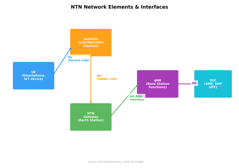
Figure 1: Episode 05 Elements
Welcome to Episode 5! In Episode 4, we charted the cosmic highway and compared LEO, MEO, GEO, and HAPS platforms. Now we descend from orbital mechanics into architecture — the engineering blueprint that determines how 5G signals actually traverse non-terrestrial segments.
The central question of this episode: Does the satellite just relay RF signals (transparent/bent-pipe), or does it actually process and regenerate them (regenerative)? The answer profoundly impacts latency, complexity, cost, capacity, and how 3GPP’s protocol stack maps onto the space segment.
The 3GPP NTN Reference Architecture

Figure 2: NTN Architecture
3GPP defines the NTN reference architecture in TR 38.821 and TS 38.300, identifying these key network elements:
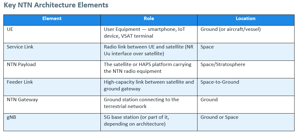
The critical architectural decision is: Where does the gNB functionality live?
Architecture A: Transparent (Bent-Pipe) Payload

Figure 3: Transparent Vs Regenerative
In the transparent architecture, the satellite is essentially a relay in the sky — it receives the signal on the service link, frequency-converts and amplifies it, and retransmits it on the feeder link (and vice versa). The satellite performs no baseband processing of the 5G NR signal.
How It Works
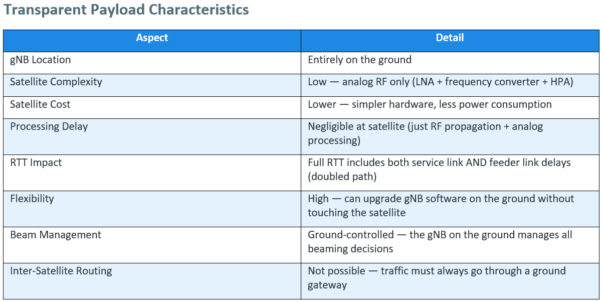
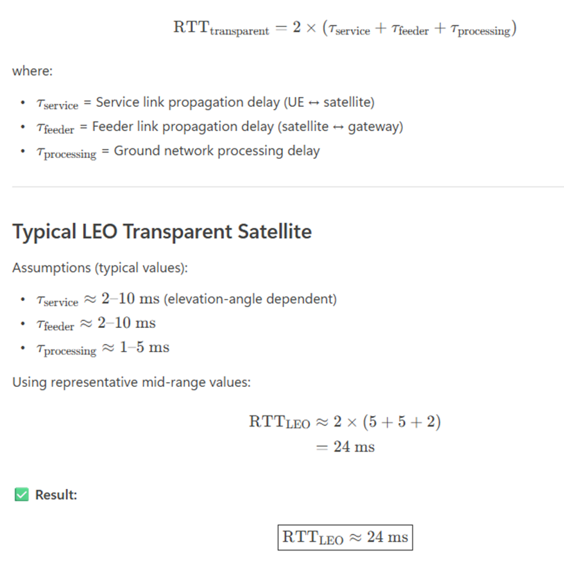
RTT Calculation — Transparent LEO (550 km)
For a UE communicating through a transparent LEO satellite:
RTT Calculation — Transparent GEO
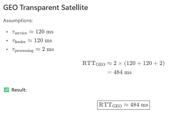
LEO transparent RTT (~24 ms): Suitable for interactive broadband and real‑time services.
GEO transparent RTT (~484 ms): Challenging for interactive applications, but acceptable for:
- Broadcasting
- IoT / M2M
- Maritime and aeronautical safety‑of‑life services
Architecture B: Regenerative Payload

Figure 4: 3GPP Timeline
In the regenerative architecture, the satellite carries some or all of the gNB functionality on-board. The satellite receives the NR signal, demodulates/decodes it, processes it at the baseband level, and re-encodes/modulates it for the feeder link. This is often described as putting a “gNB in space.”
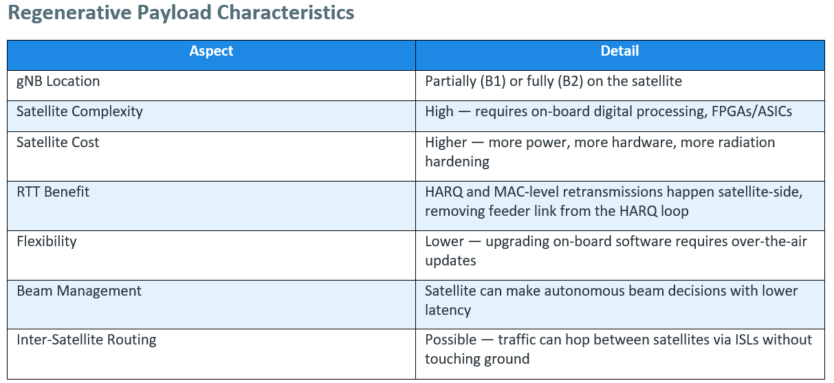
Regenerative Sub-Options (3GPP Classification)
3GPP defines two regenerative variants:
Option B1: gNB-DU on satellite, gNB-CU on ground
- The satellite carries the DU (Distributed Unit) — PHY, MAC, RLC layers — The CU (Central Unit) — PDCP, RRC, SDAP — remains on the ground — Connected via the F1 interface between satellite (DU) and ground (CU) — This is the most discussed regenerative option in Rel-17/18
Option B2: Full gNB on satellite
- The entire gNB stack (DU + CU) is on the satellite — Only the NG interface connects the satellite to the 5G core on the ground — Maximum independence — the satellite can operate with minimal ground connectivity
Architecture Decision Flow
RTT Calculation — Regenerative LEO (550 km)
For the HARQ loop (MAC-level retransmission) with a regenerative satellite:

Compare this to the transparent case where the HARQ loop includes the feeder link:
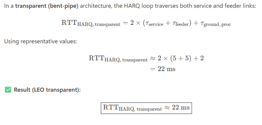
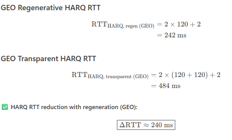
For GEO regenerative, the HARQ benefit is even more dramatic:
Key Takeaways
LEO: Regenerative payloads reduce HARQ RTT by ~45%, improving throughput and scheduler efficiency.
GEO: Regeneration is almost mandatory for interactive services.
Transparent GEO: HARQ RTT (~484 ms) severely limits:
- TCP efficiency
- Real‑time applications
- NR MAC performance
Transparent vs. Regenerative — Head-to-Head
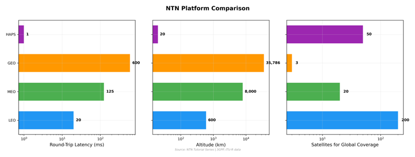
Figure 5: Orbit Comparison

The Feeder Link Advantage
One under-appreciated benefit of regenerative payloads: feeder link efficiency. In a transparent satellite, the feeder link must carry the raw NR waveform (same bandwidth as the service link). In a regenerative satellite, the feeder link carries processed data — after channel coding gain, the feeder link bandwidth requirement can be 60–80% less than the service link bandwidth. This is crucial when feeder link spectrum is scarce.
The F1 Split — Why It Matters for NTN

Figure 6: Coverage Gap
3GPP’s F1 interface separates the gNB into: — gNB-DU (Distributed Unit): PHY, MAC, RLC — time-critical, close to the antenna — gNB-CU (Central Unit): PDCP, RRC, SDAP — higher-layer, less time-sensitive
In regenerative NTN Architecture B1: — gNB-DU rides on the satellite → handles HARQ, scheduling, and beam management locally — gNB-CU stays on the ground → handles RRC (connection management), security, and core network interaction
The F1 interface between them is designed to tolerate higher latency than the FAPI or lower-layer interfaces. This makes the CU-DU split perfect for NTN, where the satellite-to-ground link adds significant delay.
F1 Delay Tolerance: — F1 can tolerate 10s to 100s of ms of delay (designed for fronthaul/backhaul scenarios) — FAPI (PHY-MAC interface) requires <1 ms latency — only feasible if PHY and MAC are co-located (both on satellite or both on ground)
This is a key design principle for our DU codebase — the split between time-critical DU functions and delay-tolerant CU functions aligns beautifully with the satellite architecture.

Trends: The Future Is Hybrid
The industry is moving toward hybrid architectures that combine transparent and regenerative elements:
-
Software-Defined Payloads: Satellites with reprogrammable digital processors that can switch between transparent and regenerative modes based on demand. Thales Alenia Space’s “Space Inspire” platform is a leading example.
-
Disaggregated Space Networks: Multiple small satellites forming a distributed system — some handling RF relay, others providing on-board processing, connected via ISLs. This mirrors the terrestrial RAN disaggregation trend (O-RAN).
-
Edge Computing in Space: With regenerative payloads, it’s possible to run edge compute workloads on the satellite — processing data closer to the source for applications like Earth observation analytics or autonomous vehicle support.
-
Multi-Orbit Integration: Systems that integrate LEO (low latency), MEO (medium capacity), and GEO (wide coverage) satellites, routing traffic dynamically based on application needs. SES’s multi-orbit strategy with O3b mPOWER (MEO) and Astra (GEO) is a prime example.
Key Takeaways
-
3GPP defines three NTN architectures: Transparent (bent-pipe), Regenerative B1 (gNB-DU on satellite, F1 split), and Regenerative B2 (full gNB on satellite) — each trading off complexity, cost, latency, and flexibility.
-
Transparent payloads are simpler and cheaper but add feeder link delay to every HARQ loop and cannot support inter-satellite routing.
-
Regenerative payloads put baseband processing on the satellite, cutting HARQ RTT nearly in half by eliminating the feeder link from the retransmission loop.
-
The F1 CU-DU split is architecturally ideal for NTN — the DU handles time-critical PHY/MAC on the satellite while the delay-tolerant CU (PDCP/RRC) stays on the ground.
-
Feeder link efficiency: Regenerative payloads can reduce feeder link bandwidth by 60–80% since processed data (not raw waveform) is transmitted to ground.
-
Real-world deployments span the spectrum: Starlink and AST SpaceMobile use regenerative, OneWeb and Lynk use transparent, and the industry trends toward hybrid software-defined payloads.
-
ISL routing is only possible with regenerative payloads — enabling pole-to-pole connectivity without ground hops, a critical advantage for global latency-sensitive services.
-
Architecture choice cascades through every NTN design decision — from satellite power budget to protocol stack to ground infrastructure requirements, as we’ll explore further in Episode 6.
Next Episode Preview
In Episode 6: NTN Protocol Stack & 3GPP Standards, we’ll map the familiar 5G NR protocol stack — PHY, MAC, RLC, PDCP, RRC, SDAP — onto the NTN architecture. We’ll trace every frame from the UE through space to the core network, decode the key 3GPP specifications (TS 38.300, TR 38.821, TS 38.213), and understand what changes (and what doesn’t) when the radio link traverses hundreds of kilometers of vacuum instead of a few hundred meters of air. Protocol nerds, this one’s for you.
Disclaimer: Published for educational purposes only. References to 3GPP, ITU‑R, and other industry sources are cited above.
NTN #5G #SatelliteArchitecture #TransparentPayload #RegenerativePayload #BentPipe #gNB #CU_DU_Split #F1Interface #3GPP #TR38821 #Starlink #OneWeb #AST #InterSatelliteLinks #SpaceComms #NTNArchitecture #TelecomTutorial
메타데이터
- post_id
- 52d7af8cf0ca
- slug
- episode-5-ntn-architecture-payload-types-52d7af8cf0ca
- url
- https://medium.com/@bcut.sunil/episode-5-ntn-architecture-payload-types-52d7af8cf0ca
- canonical_url
- https://medium.com/@bcut.sunil/episode-5-ntn-architecture-payload-types-52d7af8cf0ca
- author_url
- https://medium.com/@bcut.sunil
- status
- ok
- fetched_at
- 2026-06-12 18:14:10