Where a Robot Lives in Space: The URDF Mental Model I Wish I Had on Day One
Frames, origins, and axes sound simple until you try to describe a robot with them. Here is the progressive story that finally made URDF…
Where a Robot Lives in Space: The URDF Mental Model I Wish I Had on Day One
Frames, origins, and axes sound simple until you try to describe a robot with them. Here is the progressive story that finally made URDF click for me.
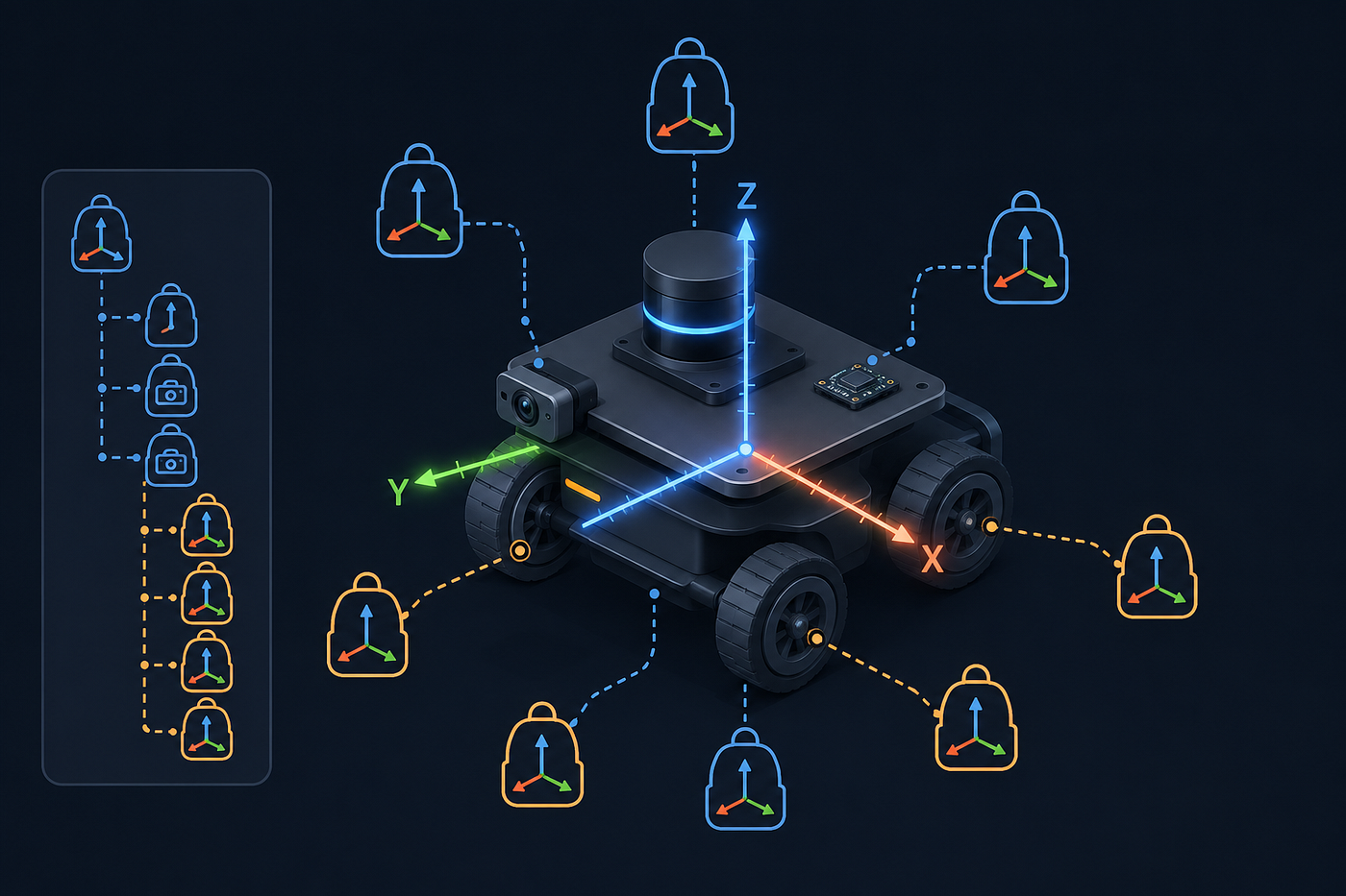
I thought I understood coordinates.
I had used x, y, and z in math class, in comuter vision, in CAD tools. So when I opened my first URDF file and saw origin xyz="0 0.15 0.05", I assumed it meant "this thing is at position (0, 0.15, 0.05)."
That assumption cost me one hour of debugging a wheel that rendered inside the chassis.
The problem was not the math. The problem was that URDF uses ordinary words — frame, origin, axis, link, joint — with meanings that feel familiar but are narrowly technical. Until you map those words precisely, URDF feels like magic. Once you map them, it becomes mechanical.
This post is the map I wish I had on day one.
The Real Question URDF Answers
Forget XML for a moment. Imagine a box on a table. I ask you: “Where is the box?”
You cannot answer without choosing a reference. “Two meters forward” only makes sense if we agree on a starting point and a direction. In robotics, that agreement is called a frame.
A frame is three things together:
- An origin — the zero point.
- Three perpendicular axes — X, Y, Z — that define forward, left, and up.
- A body those axes are attached to.
The third point is the one I missed. A frame is not a coordinate system floating in space. It is a tiny ruler glued to a specific object. If the object moves, the frame moves. If the object rotates, the frame rotates.
This is why the word “frame” is so easy to misunderstand. In everyday English, a frame is a border. In robotics, a frame is a body with a ruler attached.
A Robot Is a Family of Frames
A mobile robot is not one solid block. It is a chassis, two drive wheels, a caster, a LiDAR, a camera, and an IMU. Each of those pieces is a rigid body, and each rigid body gets its own frame.
For the robot I built while learning this, the frames looked like this:
base_link— center of the chassis, on the floor.left_wheel_link— center of the left wheel.right_wheel_link— center of the right wheel.caster_wheel_link— center of the caster sphere.laser_frame— center of the LiDAR sensor.camera_frame— center of the camera.imu_frame— center of the IMU.
URDF’s entire job is to tell ROS where each of these frames is relative to the others. That is it. Every tag in URDF serves that one purpose.
The Two Kinds of Origin
Here is where I got stuck. The word origin appears in two places in URDF, and they mean different things.
Origin in a joint
A joint connects two links. Its origin says: "The child frame lives here, measured from the parent frame."
<joint name="left_wheel_joint" type="continuous">
  <parent link="base_link"/>
  <child link="left_wheel_link"/>
  <origin xyz="0 0.15 0.05"/>
</joint>
This says: start at base_link, walk 0 m forward, 0.15 m left, and 0.05 m up. That is where the left wheel's frame is.
The ruler here is the parent’s frame.
Origin in a link
A link describes a rigid body. Inside the link, the origin says: "The geometry or mass lives here, measured from the link's own frame."
<link name="base_link">
  <visual>
    <origin xyz="0 0 0.075"/>
    <geometry>
      <box size="0.30 0.20 0.15"/>
    </geometry>
  </visual>
</link>
Here, base_link's frame is on the floor, but the chassis box is 0.15 m tall. To center the box vertically, the visual geometry must shift up by half the height. The ruler here is the link's own frame.
Two rulers. Same word. That is the two-ruler problem.
The moment this clicked, URDF stopped being confusing. Every time I saw origin, I asked: "Whose ruler am I reading?"
Position: xyz Is a Walk, Not a Point
When you see xyz="0 0.15 0.05", do not read it as "the point (0, 0.15, 0.05)." Read it as a set of instructions:
- Start at the reference frame’s origin.
- Walk 0 m along X.
- Walk 0.15 m along Y.
- Walk 0.05 m along Z.
In ROS, the convention is:
AxisPositive directionXforwardYleftZup
A negative Y value means right. A negative Z value means down.
This sounds trivial, but it matters because every xyz is relative. You cannot say "the kitchen is at (3, 4)" without saying "relative to my house." Likewise, you cannot say xyz="0 0.15 0.05" without knowing the parent frame.
Rotation: Why My Wheel Was Wrong
A cylinder in URDF is tall along the Z axis by default. If you want a wheel that rolls along the ground along X, you need the cylinder’s axle to point along Y.
To do that, you rotate the cylinder 90° around the X axis:
<origin rpy="1.5708 0 0"/>Roll-pitch-yaw means: rotate around X, then Y, then Z. For a simple wheel, only one of those three numbers is non-zero.
My first attempt used rpy="0 1.5708 0" — rotation around Y. That made the cylinder's axis point along X, so the wheel would roll along Y instead of X. The robot looked like it had two tiny barrels mounted sideways.
The lesson: rotation order and axis matter. When in doubt, physically trace where the Z axis of the geometry ends up after the rotation.
Axis: The Pin the Joint Spins Around
For a moving joint, you must also define an axis:
<axis xyz="0 1 0"/>This is the direction of the imaginary pin that the joint spins around. A wheel rolling forward along X spins around its Y axle. If the axis were 0 0 1, the wheel would spin like a top.
The axis is defined in the joint’s own frame. Combined with the geometry rotation, this determines which way the wheel actually turns when the joint receives a velocity command.
Why This Matters for Sensors
Every sensor produces data in its own frame:
- A LiDAR returns distances in
laser_frame. - A camera returns pixels that project into
camera_frame. - An IMU returns accelerations in
imu_frame.
The navigation stack needs all of this data in a common frame, usually base_link or map. URDF is the source of truth that says:
*“laser_frameis 0.17 m abovebase_link, facing forward.""*
If that frame is wrong by even a few centimeters, the obstacle at (1, 0, 0) in laser coordinates will appear in the wrong place in base coordinates. The robot will think a wall is where it is not.
This is why coordinate frames are not an academic exercise. They are the foundation of sensor fusion.
Inertial: The Physics of the Frame
If you only care about visualization, geometry is enough. If you care about physics, you need inertial properties.
Three things matter:
- Mass — how much matter is in the link.
- Center of mass — the average location of that matter.
- Moment of inertia — how the mass is distributed, which determines resistance to rotation.
For simple shapes, you can compute inertia with standard formulas. You do not need to memorize them, but you need to know that Gazebo requires them. A link with zero or wrong inertia will behave unpredictably in simulation: it might jitter, flip, or fall through the floor.
URDF as a Story
Once you see URDF this way, every tag has a clear role:
<link>— here is a rigid body.<joint>— here is how two bodies connect.<origin>— here is where the child frame or geometry lives.<axis>— here is how the joint moves.<visual>— here is what it looks like.<collision>— here is the simplified shape for physics and planning.<inertial>— here is how it behaves under force.
Every line answers one specific question about where something is or how it moves.
What I Got Wrong (So You Can Skip It)
- I treated
xyzas an absolute point. It is a displacement from a parent frame. - I confused joint origin with link origin. Joint origin uses the parent’s ruler; link origin uses the link’s own ruler.
- I rotated the wheel around the wrong axis. A Z-aligned cylinder needs roll around X to become a wheel rolling along X.
- I forgot that continuous joints need joint states.
robot_state_publishercannot compute wheel transforms without/joint_states. Fixed joints do not have this problem. - I put the caster inside the chassis. The first position I chose was entirely occluded by the chassis box. Visualizing immediately revealed the mistake.
The One-Sentence Summary
A robot is a family of frames. URDF tells ROS where each frame lives, how it moves, and what physical properties it has.
If you are starting URDF and feeling lost, do not memorize tags. Memorize this sentence. The tags are just the syntax for expressing it.
메타데이터
- post_id
- 537aac323d1e
- slug
- where-a-robot-lives-in-space-the-urdf-mental-model-i-wish-i-had-on-day-one-537aac323d1e
- url
- https://medium.com/@shoaib6174/where-a-robot-lives-in-space-the-urdf-mental-model-i-wish-i-had-on-day-one-537aac323d1e
- canonical_url
- https://medium.com/@shoaib6174/where-a-robot-lives-in-space-the-urdf-mental-model-i-wish-i-had-on-day-one-537aac323d1e
- author_url
- https://medium.com/@shoaib6174
- status
- ok
- fetched_at
- 2026-06-21 07:44:09