AWS VPC Explained: Subnets, Route Tables, and Security Groups
Four hours of debugging. One connection timeout. One concept never properly understood. This is the deep explanation with every diagram…
AWS VPC Explained:
Subnets, Route Tables, and Security Groups
Four hours of debugging. One connection timeout. One concept never properly understood. This is the deep explanation with every diagram that would have saved that time.
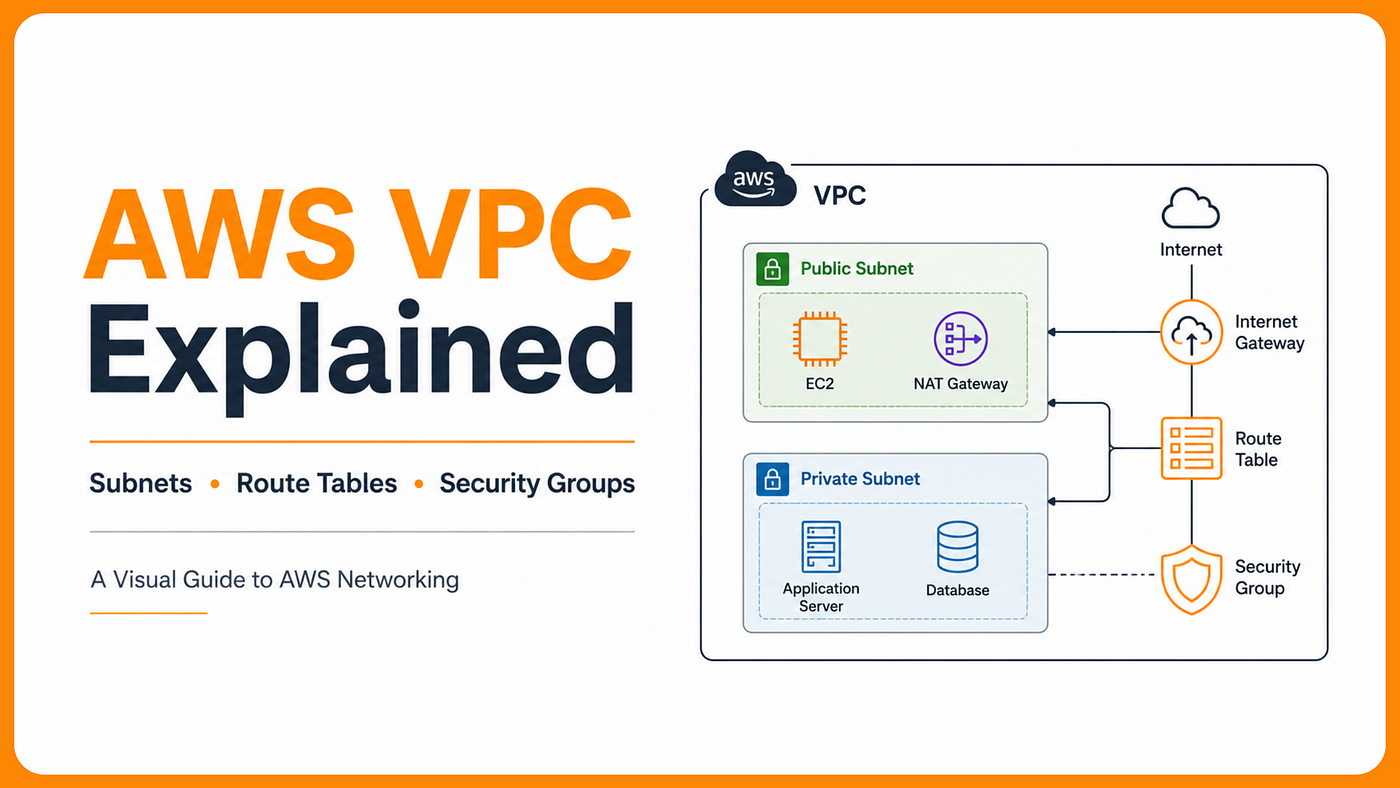
If you’ve read my earlier article, “AWS VPC Advanced: A Deep Dive into Intricate Networking and Security,” you’re already familiar with the broader networking landscape like VPC Peering, VPNs, Direct Connect, Transit Gateways, PrivateLink, and Infrastructure as Code (IaC) with Terraform.
This article returns to the foundation that powers all of those technologies: the Amazon VPC itself. But instead of covering the basics, we’re diving deep into the mechanics that most engineers never explore.
We’ll go beyond simple explanations of subnets and route tables to examine how the VPC router evaluates routes, why CIDR design directly impacts scalability and future growth, how Security Groups and Network ACLs interact at the packet level, and how to translate these concepts into production-ready Terraform modules.
Let’s dive in.
VPC as a Software-Defined Network
A VPC isn’t just a CIDR block with some subnets. It’s a fully software-defined network (SDN) layer that AWS implements via its Hyperplane and Nitro infrastructure. Every “router,” “gateway,” and “table” you configure is a logical construct a set of rules the underlying AWS network fabric enforces at the hypervisor level, not a physical box you’re provisioning.
This matters because it explains behaviors that confuse engineers coming from on-prem networking. There’s no broadcast domain: ARP, broadcasts, and multicast don’t work the way they do on a physical LAN. The VPC router is implicit and omnipresent: every subnet gets a router at the .1 address of its CIDR range automatically. Route evaluation, security group evaluation, and NACL evaluation all happen per-packet at line rate, distributed across the underlying fabric.
CIDR sizing you actually need to get right
A /16 gives 65,536 addresses. AWS reserves 5 per subnet. But the real question is how to size subnets for what they'll hold at peak — especially if you run Kubernetes, where each pod consumes one IP from the subnet, not just each node.
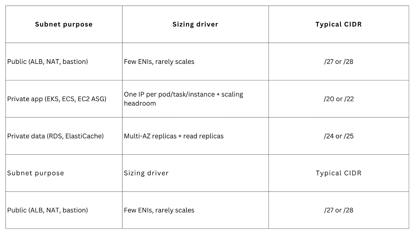
EKS Pod Exhaustion: Why Your Cluster Fails Before Your Nodes Do
By default, the AWS VPC CNI plugin assigns an IP address from your VPC subnet to every Kubernetes pod. This means IP consumption grows quickly as your cluster scales. For example, a subnet with a /24 CIDR block provides only about 251 usable IP addresses, which can be exhausted surprisingly fast by a large Amazon EKS node group running hundreds of pods. Once the subnet runs out of available IPs, new pods cannot be scheduled even if the nodes still have CPU and memory available.
To avoid this problem, AWS recommends using larger subnets such as /19 or /20 for EKS workloads. Another option is to enable Prefix Delegation by setting ENABLE_PREFIX_DELEGATION=true. Instead of allocating individual IP addresses one by one, Prefix Delegation assigns a /28 IP prefix to each Elastic Network Interface (ENI). This allows the ENI to manage multiple pod IPs more efficiently and can increase pod density by roughly 16 times, significantly reducing the risk of subnet IP exhaustion.
VPC Structure: The Three-Tier Architecture
Every production AWS network starts with the same foundation: one VPC spanning all availability zones in a region, with three tiers of subnets per AZ. The color coding in this diagram isn’t decoration, it encodes internet exposure. Teal can talk to the internet both ways. Amber can initiate outbound only. Coral has no internet path at all.
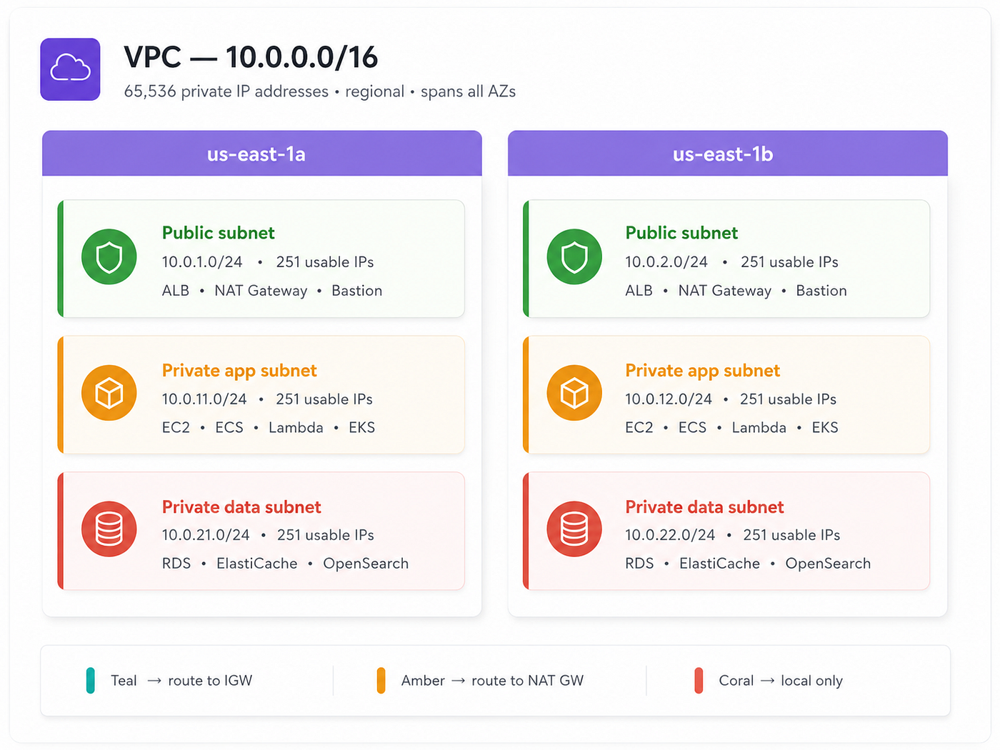
The three-tier pattern is not a suggestion; it’s the production standard for a reason. Putting your RDS instance in a public subnet to “make it easier to connect” is one of the most common security incidents in AWS. The data subnet having no internet route at all isn’t a firewall rule you could accidentally disable; it’s a missing route entry that simply doesn’t exist.
Traffic Flow: IGW and NAT Gateway
The internet gateway (IGW) is the front door of your VPC. Attaching it doesn’t make anything public; it just makes the door available. The route table decides which subnets can use it. For resources in private subnets that need to initiate outbound internet calls (downloading packages, calling external APIs), the NAT gateway acts as a proxy: it goes out so the private resource doesn’t have to expose itself.
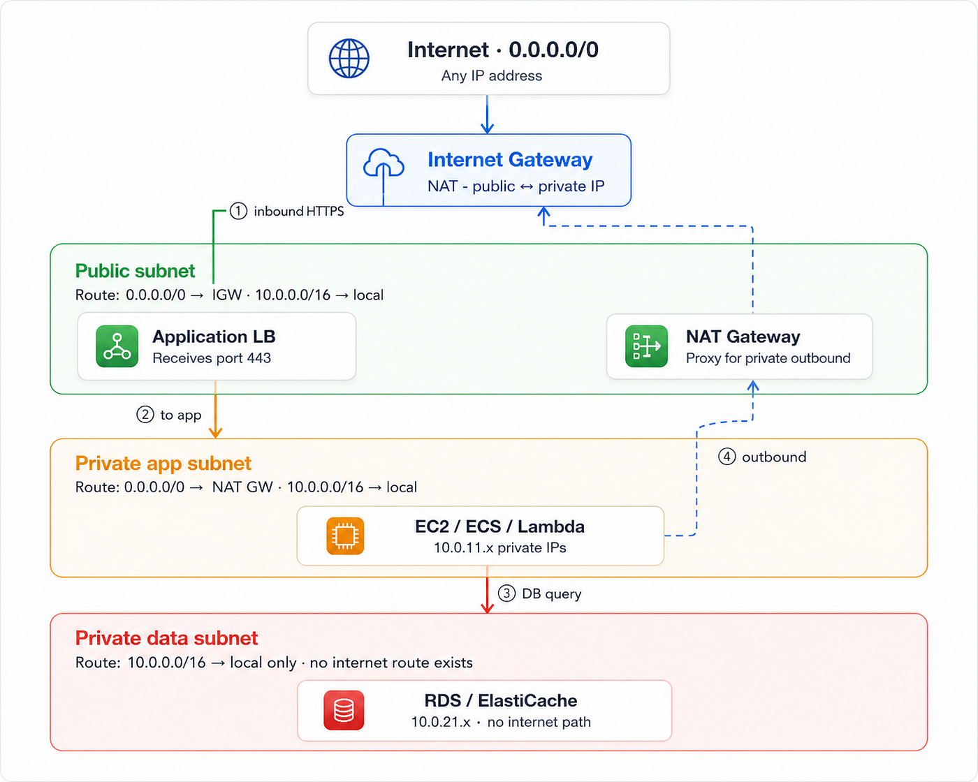
Follow the numbered arrows:
① inbound hits IGW → ALB,
② ALB to app servers,
③ app queries DB,
④ dashed = outbound-only via NAT GW → IGW.
The data subnet has no second route; no path exists by design, not by firewall.
One NAT gateway per AZ, not per region
A NAT gateway operates in one AZ. If us-east-1a and us-east-1b both route through a single NAT in us-east-1a, you incur cross-AZ data transfer charges on every packet and if that AZ goes down, both private subnets lose internet access simultaneously. Create one NAT gateway per AZ; route each AZ’s private subnet RT through the NAT in the same AZ.
Route Tables: How the VPC Router Decides
A route table is a set of rules that determines where traffic goes based on destination IP. The VPC router evaluates them using longest prefix match; the most specific CIDR wins.10.0.0.0/16 — local always beats 0.0.0.0/0 — IGW for intra-VPC traffic because /16 is more specific than /0.
The local route is immutable; it cannot be removed, and it always matches intra-VPC traffic first. This means you can never “break” VPC-internal connectivity through route table misconfiguration alone. You can only break outbound-to-internet or cross-VPC paths. Static routes also always beat BGP-propagated routes of equal prefix length, which matters when debugging hybrid connectivity.
Security Groups: Stateful, Chainable, Reference-Based
A security group is a virtual firewall attached to an individual resource, not a subnet, not a floor, a specific resource. Being in the right subnet gets traffic to the hallway. The security group is the lock on the door that decides who actually enters.
Security groups are stateful: if you allow inbound port 443, the return traffic for that TCP session is automatically permitted outbound; the security group tracks the connection. This is fundamentally different from NACLs, which are stateless and require explicit rules for both directions, including ephemeral return ports (1024–65535).
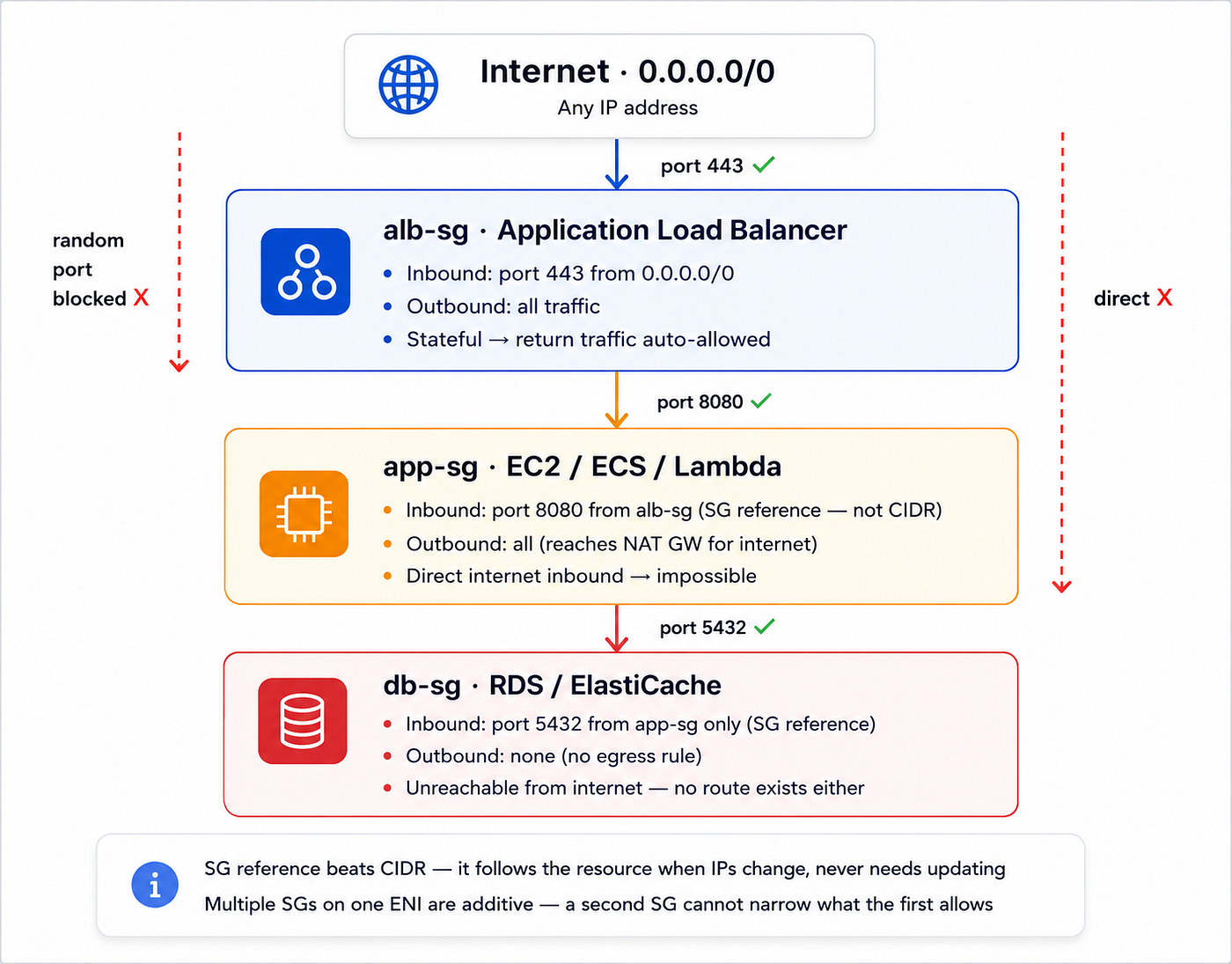
Red dashed lines show what gets blocked: random ports to the ALB, direct internet-to-app, direct anything-to-DB. The chain uses security group references so new resources inherit access automatically when they join the right SG.
NACLs vs security groups, when to use each
Use security groups for everything internal: they’re stateful, resource-scoped, and use SG references. Reserve custom NACLs for coarse subnet-level blocking: denying a known-bad IP range from your entire public subnet tier regardless of which security group a resource has. Never replicate SG rules in NACLs; it doubles maintenance for no real security gain.
Advanced Connectivity: TGW, Peering, VPC Endpoints
The single-VPC three-tier model is the foundation. At scale, production environments extend it in three directions: VPC Peering for simple point-to-point connections, Transit Gateway for multi-VPC and hybrid topologies, and VPC Endpoints for pulling AWS service traffic off the public internet entirely.
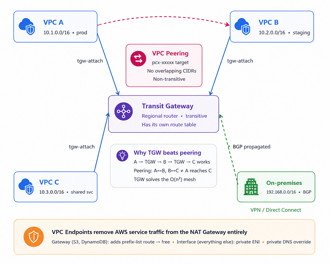
Transit Gateway is a hub each VPC attaches once and can reach every other attachment transitively. VPC Peering (dashed arc) is point-to-point and non-transitive. On-prem connectivity via VPN/DX arrives at the TGW via BGP-propagated routes, a separate route table from your VPC’s.
The most subtle bug in hybrid connectivity: a packet from your VPC toward on-prem is evaluated by two independent route tables, your VPC’s subnet route table (which must have a tgw-xxx target for the on-prem CIDR) and the Transit Gateway’s own route table (which must know which VPN/DX attachment to forward to). Both must be correct or traffic silently drops.
Production Terraform Module
The following builds on the three-tier foundation from the basic version and adds what production actually needs: VPC Flow Logs for REJECT traffic (your primary debug signal), a Gateway Endpoint pulling S3 traffic off the NAT Gateway, and an Interface Endpoint pattern for Secrets Manager. The outputs are structured for consumption by a separate Transit Gateway module.
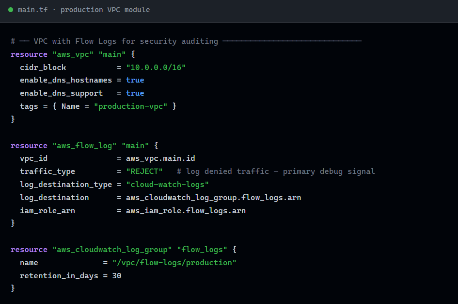
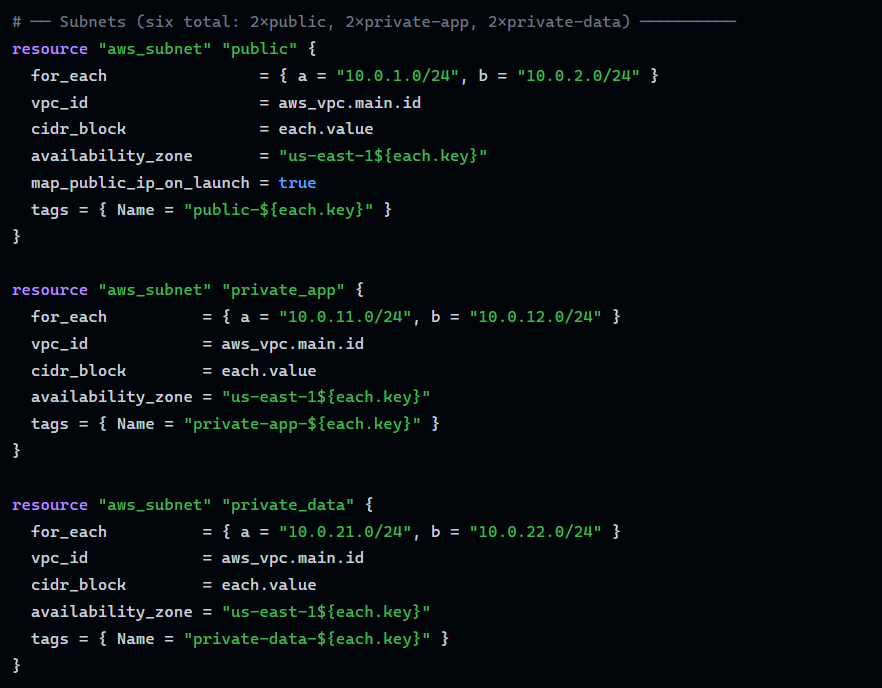
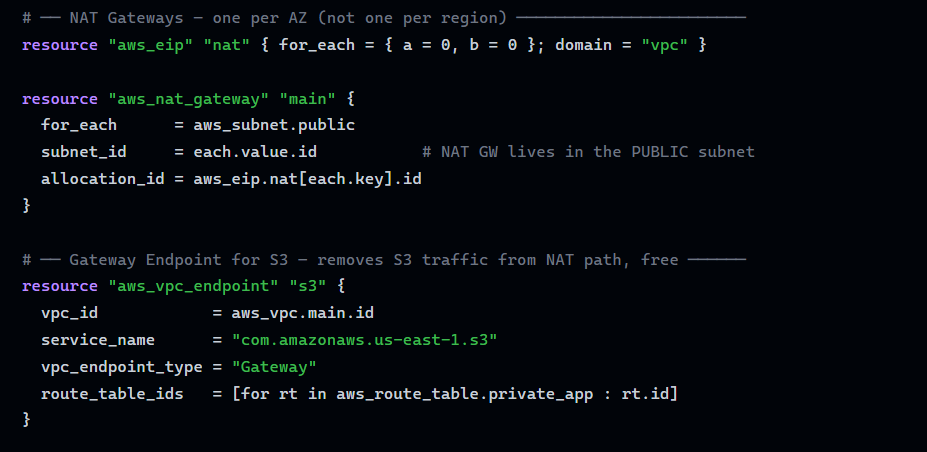
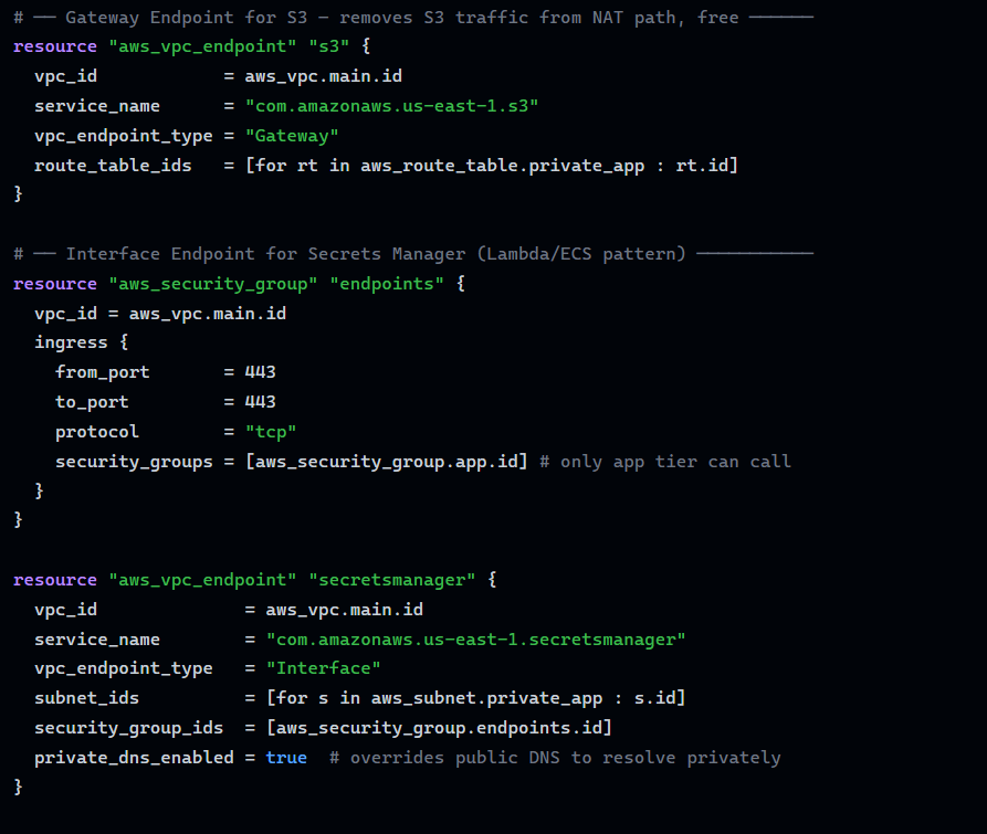
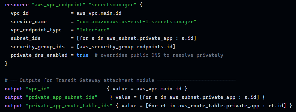
The private_app_route_table_ids output is the integration point: a separate TGW module (see the companion article) consumes this list to inject aws_route resources pointing non-local CIDRs at the TGW attachment without this module needing any knowledge of the TGW topology. VPC module owns local routing; the TGW module owns cross-VPC routing.
Debugging Checklist
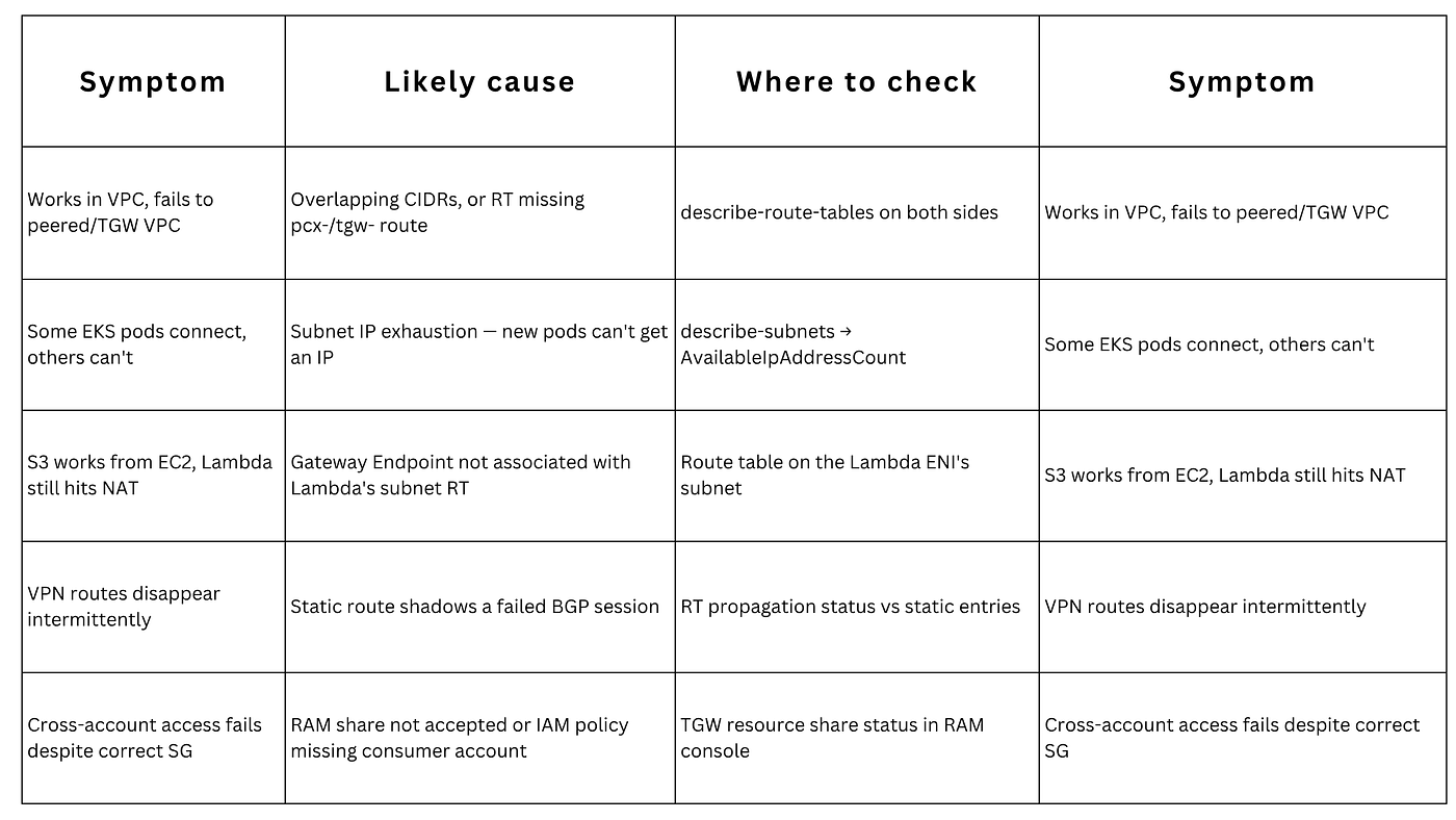
The five original mistakes (subnet labeled “public” but no IGW route, Lambda in VPC with no NAT, SG allows wrong source, single NAT gateway for multiple AZs, default VPC in production) remain the most common single-VPC causes. At scale, add these advanced failure modes.
1. Subnet called “public” but has no IGW route
Creating a subnet does not make it public. Only a route table with 0.0.0.0/0 IGW does.
Fix: Create a route table with 0.0.0.0/0 → your IGW. Associate it with the subnet explicitly.
2. Lambda in VPC with no NAT gateway
Putting Lambda in a VPC removes its default internet access. Without a NAT GW in the private subnet’s route table, it cannot call external APIs or reach AWS public endpoints.
Fix: Add NAT GW to a public subnet and add a route in the Lambda’s private subnet RT, or use VPC Endpoints for AWS services to skip the NAT GW entirely.
3. Security group references wrong source
The inbound rule says “allow port 5432 from 10.0.0.0/8,” but the app server’s IP is 172.16.x.x. Rule never matches.
Fix: Use security group references (from app-sg) instead of CIDR ranges for all internal traffic; it follows the resource regardless of IP.
4. One NAT gateway for multiple AZs
Cross-AZ NAT traffic incurs data transfer charges. More critically, if the NAT GW’s AZ fails, all private subnets across all AZs lose internet simultaneously.
Fix: One NAT GW per AZ. Each AZ’s private subnet RT points to the NAT GW in the same AZ.
5. Interface Endpoint reachable but connection refused
Lambda or ECS can resolve the endpoint’s private DNS, but gets “connection refused.” The endpoint’s ENI has its own security group.
Fix: Add an inbound rule to the endpoint’s security group allowing port 443 from the caller’s security group (app-sg).
Advanced failure mode reference
Where This Leaves You
The mental model from the foundational article subnets for location, route tables for direction, security groups for permission still holds. What changes as you scale is that route tables stop being single-VPC artifacts (they now route toward peering connections, Transit Gateways, and VPN/Direct Connect attachments), security groups stop being the only enforcement layer (PrivateLink endpoints carry their own), and CIDR planning becomes an organization-wide constraint, not a per-VPC decision.
If you haven’t yet, the companion piece “What is AWS VPC Advanced: A Deep Dive into Intricate Networking and Security” covers the peering, Transit Gateway, PrivateLink, and IaC patterns referenced throughout this article in full depth, including the multi-account RAM sharing patterns and security best practices that sit one layer above everything covered here.
The mental model that makes VPCs click:
Subnets for location · Route tables for direction · Security groups for permission
메타데이터
- post_id
- 562e622be858
- slug
- aws-vpc-explained-subnets-route-tables-and-security-groups-562e622be858
- url
- https://towardsaws.com/aws-vpc-explained-subnets-route-tables-and-security-groups-562e622be858
- canonical_url
- https://towardsaws.com/aws-vpc-explained-subnets-route-tables-and-security-groups-562e622be858
- author_url
- https://medium.com/@servifyspheresolutions
- status
- ok
- fetched_at
- 2026-06-23 03:48:11