Get Started with MSP430 MCU and Mecrisp Cross
Tethered Forth and Serial Protocol
Get Started with MSP430 MCU and Mecrisp Cross
Tethered Forth and Serial Protocol
With the success of my earlier digital dice project, I picked up another chance to use Mecrisp Cross on a low RAM resource MSP430 MCU (i.e. MSP430G2452). The project is to implement a serial bit protocol, like the Parallax Propeller firmware loader protocol.
1. Mecrisp Cross
Mecrisp Cross is a tethered Forth between the host and the target. The host acts like a code debugger, but with Forth scripting capability. The target is a MSP430 MCU that doesn’t have enough RAM resource to run Forth by itself. The host Forth runs on a STM32F407 and connects to the target over the standard MSP430 2-wire SWDIO/SWCLK debug bus.
With tethered Forth, you can develop and debug MSP430 Forth code interactively on the target (MSP430G2452). And once the code is completed, it is compiled into binary without any overhead from the host’s Forth environment itself.
2. MSP430 MCU
After a MSP430 MCU in this case MSP430G2452 is selected, some essential information comes from its MCU datasheet:
2.1 terminal functions table
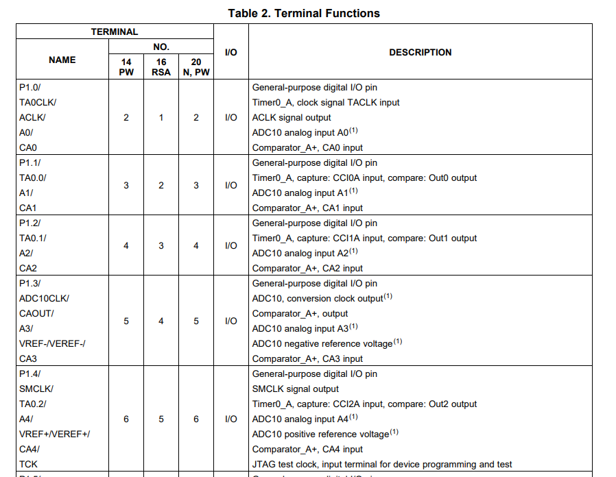
For example, not all GPIO pin can serve as ADC10 analog input, similarly Timer0 capture can only happen on certain pins for example. These will determine the pinouts of your schematic design.
2.2 Various memory address of registers and interrupt vector addresses


Mecrisp Forth/Cross already has these register addresses defined as constants. Fortunately a lot of MSP430 MCUs adopt the same address constants. So these tables are almost universal across different MSP430 MCUs.
The bit fields for each register is detailed inside the user manual.
For example, TACTL register has a lot of bit fields. Here is an example table in “Timer_A” chapter of the user manual:

The next important question is how to set these register fields in order to use the timer hardware module. The c-code examples in the zip file (SLAC467) are very helpful. It has plenty of examples showing these bit fields configured in various timer applications.
Note that C code also defines a bunch of address constants in a “msp430.h” file. It’s helpful to find the corresponding “msp430g2452.h” file for our MCU.
The next step is to turn the knowledge from relevant C examples into Forth code.
3. Mecrisp Cross Forth Code
The following is a very verbose way of defining all the bit fields for TACTLand BCSCTL3 registers.
host
new
+jtag
target

 : TA0CTL_MC<< ( x -- ) 4 lshift ; \ Timer A mode control 1
      0 constant MC_0      \ Timer A mode control: 0 - Stop
      1 constant MC_1      \ Timer A mode control: 1 - Up to CCR0
      2 constant MC_2      \ Timer A mode control: 2 - Continous up
      3 constant MC_3      \ Timer A mode control: 3 - Up/Down
 : TA0CTL_ID<< ( x -- ) 6 lshift ; \ Timer A clock input divider 1
      0 constant ID_0      \ Timer A input divider: 0 - /1
      1 constant ID_1      \ Timer A input divider: 1 - /2
      2 constant ID_2      \ Timer A input divider: 2 - /4
      3 constant ID_3      \ Timer A input divider: 3 - /8
 : TA0CTL_TASSEL<< ( x -- ) 8 lshift ; \ Timer A clock source select 1
      0 constant TASSEL_0      \ Timer A clock source select: 0 - TACLK
      1 constant TASSEL_1      \ Timer A clock source select: 1 - ACLK
      2 constant TASSEL_2      \ Timer A clock source select: 2 - SMCLK
      3 constant TASSEL_3      \ Timer A clock source select: 3 - INCLK
 : BCSCTL3_LFXT1S<< ( x -- ) 4 lshift ; \ Mode 0 for LFXT1 (XTS = 0)
      0 constant LFXT1S_0      \ Mode 0 for LFXT1 : Normal operation
      1 constant LFXT1S_1      \ Mode 1 for LFXT1 : Reserved
      2 constant LFXT1S_2      \ Mode 2 for LFXT1 : VLO
      3 constant LFXT1S_3      \ Mode 3 for LFXT1 : Digital input signal

 : configure ( -- )
 \ timer clock                    \ LFXT1 feeds ACLK
  LFXT1S_2 BCSCTL3_LFXT1S<<       \ VLO = 12 kHz  (or LFXT1S_0 = 32768-Hz crystal on MSP430G2201)
              BCSCTL3 cbis!       \ note: XTS = 1 is not supported in MSP430G2201 devices
 \ timer
   MC_2 TA0CTL_MC<<
    ID_0 TA0CTL_ID<<
     TASSEL_1 TA0CTL_TASSEL<<
              + + TACTL bis!     \ TA0CTL @ bin. 0000000100100001 ok.
 ;

 : main ( -- ) cr
   configure
   0 TAR !        \ clear counter
   TAR @ . cr     \ read free running counter
   TAR @ . cr
   TAR @ . cr
   TAR @ . cr
   TAR @ . cr
   TAR @ . cr
   TAR @ . cr
   TAR @ . cr
 ;

mainlshift, cbis! and cbic! are used to manipulate the bit fields of the MSP430 registers. Mecrisp Cross dictionary contains many other Forth primitives on the target device. Once you are familiar with these constants, the code doesn’t have to be that verbose.
In the last step, the complete binary code, both “main” and “IRQ” functions are stored in the vector table like this:
 host           \ leave target mode, enter host mode
  $FFE4 vector P1.3-int-handler        \ push button interrupt vector
  $FFFE vector main crosscompile flashtarget -jtag run     \ crosscompile the code above and flash it to the target
\ hexdump          \ print a neat hexdump of the cross compiled binary
\ t-listing          \ t-listing shows what the cross compiler did
\ disimage      \ disamige produces a disassembly listing of the target binary
See example interrupt vector functions.
hexdumpcan produce bin file to be programmed into MSP430 flash with its UNIFLASH directly, especially for mass production.
4. Parallax Propeller Serial Protocol
The goal of the project is to implement a serial data protocol like the one used by Parallax Propeller MCU to flash its firmware.
It is a time slot based bit protocol. The BIT_ZERO is represented by 2T time slot, BIT_ONE is represented by 1T time slot. Once triggered by a falling edge, the receiver samples at 1.5T time slot to determine whether it’s a BIT_ZERO or BIT_ONE.
The nice thing about this protocol is that 1T or 2T aren’t predetermined. To establish the timing, the sender will send two calibration pulses one with 1T time slot and the other with 2T time slot, before sending the following data bits.
A typical RS232 serial protocol can be hijacked to implement this serial protocol. Because sending 0xF9 on a serial bus will appear as
0_1_0_0_1_1_1_1_1
Note that the first zero of 1T is the start bit, and the second zeros of 2T is due to RS232 sending LSB first of byte 0xF9.
Similarly to send BIT_ZERO, one sends byte 0xFF over the serial bus; to send BIT_ONE, one sends byte 0xFE instead.
Here is FSM code in Forth to detect BIT_ZERO and BIT_ONE with the help of MSP430 timer capture/compare functions.
new
+jtag
target

$166 constant TACCTL2
$176 constant TACCR2

0 constant IDLE
1 constant HL_E1   \ to derive 1t
2 constant LL_E2
3 constant HL_E2   \ to derive 2t
4 constant BIT_LL
5 constant BIT_HL  \ magic byte 0x78
6 constant TX_BIT
7 constant EXIT    \ failed

0 variable state
0 variable t_LL_E1
0 variable t_HL_E1
0 variable t_LL_E2
0 variable t_HL_E2
0 variable t_1
0 variable t_1p5
0 variable bit_cnt
0 variable byte_in
0 variable byte_cnt
0 variable byte_out

: fsm
state @ CASE
  IDLE OF
     taccr0 @ dup t_LL_E1 !   \ save falling edge time from TAR
     $4910 tacctl0 !          \ rising edge+cap+int
     60000 + taccr2 !         \ xms timeout
     16 tacctl2 !             \ enable int
     HL_E1 state !
  ENDOF
  HL_E1 OF
     taccr0 @ t_HL_E1 !  \ save rising edge time from TAR
     $8910 tacctl0 !     \ set to capture next falling edge
     LL_E2 state !
  ENDOF
  LL_E2 OF
     taccr0 @ t_LL_E2 !  \ save falling edge time from TAR
     $4910 tacctl0 !     \ rising edge cap int
     HL_E2 state !       \ set state to LL_E2
  ENDOF
  HL_E2 OF
     taccr0 @ t_HL_E2 !                                \ save rising edge time from TAR
     t_HL_E1 @ t_LL_E1 @ - t_1 !                       \ save 1t time
     t_HL_E2 @ t_LL_E2 @ - t_HL_E1 @ t_LL_E1 @ -  2dup \ calculate time between edges
     - 0< if
        EXIT state !                                   \ calibration failed; jump to EXIT
     else
        + 2/ t_1p5 !                                   \ set to compare at 1.5t
        8 bit_cnt !                                    \ set bit counter to 7
        0 byte_in !
        0 byte_cnt !
        $8910 tacctl0 !                                \ set to capture next falling edge
        BIT_LL state !
        tar @ 60000 + taccr2 !                         \ kick timeout
     then
  ENDOF
  BIT_LL OF
    t_1p5 @ taccr0 +! \ 1.5T later
    $0010 tacctl0 !   \ switch to comp mode
    tar @ 60000 + taccr2 !                         \ kick timeout
    BIT_HL state !
  ENDOF
  BIT_HL OF
    1 10 lshift tacctl0 bit@  if \ read scci high
       byte_in @ shl 1+ byte_in !
    else
       byte_in @ shl byte_in !
    then

    bit_cnt @ 1- dup
    0= if \ byte received
      drop
      byte_cnt @ case
        0 of \ header byte
         byte_in @ $78 = if       \ compare with 0x78
           tar @ 60000 + taccr2 ! \ kick timeout
           0 byte_in !
           $8910 tacctl0 !        \ set to capture next falling edge
           BIT_LL state !
           8 bit_cnt !            \ set bit counter to 8 for second byte
         then
        ENDOF
        1 of                           \ cmd byte
          1 7 lshift byte_in bit@  if  \ MSB HIGH
            TX_BIT state !
            tar @ 60000 + taccr2 !     \ kick timeout
            103 byte_out !             \ test value only
            byte_out @ shl  byte_out ! \ add zero as start bit
            11 bit_cnt !               \ preset + start bit + 8-bit + end
            tar @ 200 + taccr1 !       \ kickstart first int
            1 4 lshift tacctl1 bis!    \ int
          else
            byte_in @ p1out c!         \ set 5 bits: p2.7(H2), p2.6(H1), p1.7(S3), p1.6(S2), p1.5(S1);
          then
        ENDOF
      ENDCASE
      byte_cnt @ 1+ byte_cnt !
   else
     bit_cnt !
     $8910 tacctl0 ! \ set to capture next falling edge
     BIT_LL state !
    then
  ENDOF
  TX_BIT OF
    t_1 @ taccr1 +!
    1 6 lshift p1out cxor!    \ test signal

    bit_cnt @ 1- dup
    0= if
       1 2 lshift tacctl1 ! \ set
    else
       bit_cnt !
       1 byte_out bit@ if
         1 7 lshift tacctl1 bic!      \ outmod 001 (set)
       else
         1 7 lshift tacctl1 bis!      \ outmod 101 (reset)
       then
       byte_out @ shr byte_out !
    then
  ENDOF
  EXIT OF
    IDLE state !         \ set next state to IDLE
    $8910 tacctl0 !      \  falling edge sync. cap int
    0 tacctl2 !          \ clear timeout
    1 5 lshift tacctl1 ! \ outmod 001 (set)
    lpm1                 \ sleep
  ENDOF

ENDCASE
;

: ser_tx_init
  1 2 lshift p1dir cbis!  \ p1.2 output
  1 2 lshift p1sel cbis!  \ p1.2 timer function
  1 2 lshift tacctl1 bis! \ output high
  1 5 lshift tacctl1 !    \ outmod 001 (set)
;

: init                      \ signal on negative input; reference on positive input
   16MHz
   1 p1dir cbis!            \ p1.0 output
   1 6 lshift p1dir cbis!   \ p1.6 output
   1 1 lshift p1ren cbis!   \ p1.1 timer function; pull-up
   1 1 lshift p1dir cbic!   \ p1.1 as input
   1 1 lshift p1out cbis!
   1 1 lshift p1sel cbis!
   $220 TACTL  !            \ smclk, cont. Mode
   ser_tx_init
   EXIT state !
   fsm
;

: timer_int
  wakeup  \ wakeup from sleep
  fsm
;

: timer_int2
  taiv @ case
    2 OF \ cc1
      fsm
    ENDOF
    4 OF \ cc2
      EXIT state !
      fsm
     1 6 lshift p1out cxor!
    ENDOF
  endcase
;

: main
  init
  eint
;

host               \ leave target mode, enter host mode
$fff2 vector timer_int                 \ timer t0 interrupt vector
$fff0 vector timer_int2        \ timer t1 interrupt vector
$FFFE vector main
crosscompile flashtarget -jtag run     \ crosscompile the code above and flash it to the targe
The rest of the functions are listed below. The FSM function is triggered by timer (CC0) interrupt on each signal transition, either rising or falling edge. Time out (CC2) jumps FSM to the beginning if something goes wrong.
: init                      \ signal on negative input; reference on positive input
   16MHz
   1 p1dir cbis!            \ p1.0 output
   1 6 lshift p1dir cbis!   \ p1.6 output
   1 1 lshift p1ren cbis!   \ p1.1 timer function; pull-up
   1 1 lshift p1dir cbic!   \ p1.1 as input
   1 1 lshift p1out cbis!
   1 1 lshift p1sel cbis!
   $220 TACTL  !            \ smclk, cont. Mode
   ser_tx_init
   EXIT state !
   fsm
;

: timer_int
  wakeup  \ wakeup from sleep
  fsm
;

: timer_int2
  taiv @ case
    2 OF \ cc1
      fsm
    ENDOF
    4 OF \ cc2
      EXIT state !
      fsm
     1 6 lshift p1out cxor!
    ENDOF
  endcase
;

: main
  init
  eint
;

host               \ leave target mode, enter host mode
$fff2 vector timer_int                 \ timer t0 interrupt vector
$fff0 vector timer_int2        \ timer t1 interrupt vector
$FFFE vector main
crosscompile flashtarget -jtag run     \ crosscompile the code above and flash it to the targe
Here is the sequence of serial bytes to send over P1.1 (MSP430 RX)
0xF9, 0xFE, 0xFF, 0xFF, 0xFF, 0xFF, 0xFE,0xFE,0xFE, …
corresponds to:
calibration byte, BIT0, BIT1, BIT1, BIT1, BIT1,BIT0, BIT0, BIT0, …
The magic number 0x78 is used as a header preceding the rest of the payload bytes.
Currently the sender can use 115200baud rate serial port to send these data. For slower baud rate, when MCLKat 16MHz is faster enough to measure 1.5T with enough counts.
To serial TX data back is a bit tricky. Notice that in order to send out 8-bit, the timer interrupt needs to be triggered 11 times.
The outmode of set/reset is happening on the timer compare next interrupt (taccr1 == tar). So it’s a bit like writing Verilog sequential code, where things happen at the next clock cycle.
1 byte_out bit@ if
  1 7 lshift tacctl1 bic!      \ outmod 001 (set)
else
  1 7 lshift tacctl1 bis!      \ outmod 101 (reset)
then
Here is the confusing c-code snippet.
 else
    {
      CCTL0 |=  OUTMOD2;                    // TX Space
      if (RXTXData & 0x01)
      CCTL0 &= ~ OUTMOD2;                   // TX Mark
      RXTXData = RXTXData >> 1;
      BitCnt --;
    }
But as long as you realize CCTL0 bit setting only takes effect at next timer interrupt, these set/reset steps aren’t worrying.
메타데이터
- post_id
- 62eef912a2bf
- slug
- get-started-with-msp430-mcu-and-mecrisp-cross-62eef912a2bf
- url
- https://medium.com/@circuit4us/get-started-with-msp430-mcu-and-mecrisp-cross-62eef912a2bf
- canonical_url
- https://medium.com/@circuit4us/get-started-with-msp430-mcu-and-mecrisp-cross-62eef912a2bf
- author_url
- https://medium.com/@circuit4us
- status
- ok
- fetched_at
- 2026-07-20 07:29:46