How I Tuned a PID Controller for DC Motor Speed Control — And What the Graph Revealed
A practical walkthrough of implementing proportional-integral-derivative control on a real DC motor system
How I Tuned a PID Controller for DC Motor Speed Control — And What the Graph Revealed
A practical walkthrough of implementing proportional-integral-derivative control on a real DC motor system
Introduction
Speed control is one of the most fundamental challenges in motor-driven systems. Whether you’re building a robotic arm, a conveyor system, or a precision fan controller, the ability to command a motor to reach and hold a target speed — accurately and quickly — is non-negotiable.
In this project, I implemented a PID (Proportional-Integral-Derivative) controller to regulate the speed of a DC motor. The goal was simple: minimize settling time and reduce steady-state error to near zero. The results exceeded my expectations.
Why PID?
PID is the workhorse of industrial control systems. It’s not the newest algorithm, but it remains the most widely deployed controller in the world — and for good reason.
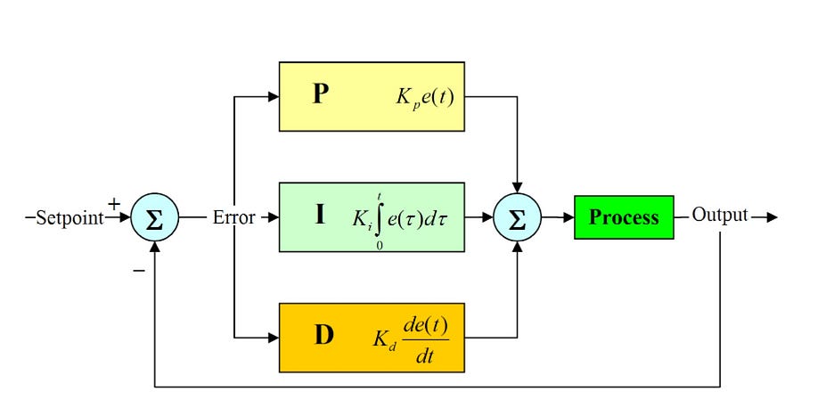
A PID controller computes an output based on three terms:
∙ P — Proportional: Generates a corrective output proportional to the current error. Fast but can cause overshoot.
∙ I — Integral: Accumulates past errors to eliminate steady-state offset. Essential for accuracy.
∙ D — Derivative: Predicts future error based on rate of change. Acts as a brake to reduce overshoot and oscillation.
The combined output:
u(t) = Kp·e(t) + Ki·∫e(t)dt + Kd·de(t)/dt
The Experiment Setup
The system consisted of:
∙ A DC motor with encoder feedback
∙ A microcontroller running the PID algorithm in real time
∙ A real-time speed graph to visualize the system response
The reference (setpoint) was set, the system was powered on, and the controller was tasked with bringing the motor speed to the target as fast and accurately as possible.
Tuning the Gains
Gain tuning is where most engineers spend 80% of their time. Too much Kp → oscillation. Too little Ki → persistent error. Too much Kd → noise amplification.
After careful tuning:
∙ The rise time was fast
∙ The overshoot was kept minimal
∙ The settling time was excellent
∙ The steady-state error was nearly eliminated
The response graph captured live during testing confirmed a textbook-quality second-order system response.
What the Graph Tells You
The real-time graph is the most honest feedback you can get. It reveals:
∙ Whether your Kp is too aggressive
∙ If the integrator is winding up
∙ How quickly the derivative term is suppressing oscillations
In my experiment, the graph showed a clean, fast rise to setpoint with negligible overshoot and a flat, stable steady-state — exactly what you want.
Key Takeaways
-
PID remains a powerful and practical control strategy for motor systems
-
Gain tuning is iterative — start conservative and increase gradually
-
Real-time feedback (graphs, encoders) is critical for validation
-
The derivative term is your friend for reducing overshoot — if your signal isn’t too noisy
Interested in control systems, embedded engineering, or motor control? Follow me for more practical experiments.
메타데이터
- post_id
- 6ed0901ef011
- slug
- how-i-tuned-a-pid-controller-for-dc-motor-speed-control-and-what-the-graph-revealed-6ed0901ef011
- url
- https://medium.com/@ameenullahi/how-i-tuned-a-pid-controller-for-dc-motor-speed-control-and-what-the-graph-revealed-6ed0901ef011
- canonical_url
- https://medium.com/@ameenullahi/how-i-tuned-a-pid-controller-for-dc-motor-speed-control-and-what-the-graph-revealed-6ed0901ef011
- author_url
- https://medium.com/@ameenullahi
- status
- ok
- fetched_at
- 2026-06-09 15:37:30