The Ion Cooling Engine: Anatomy of a fanless machine.
Inside the corona discharge physics, electron avalanches, ion mobility, and electrode geometry, that let engineers turn a 300-year-old…
The Ion Cooling Engine: Anatomy of a fanless machine.
Inside the corona discharge physics, electron avalanches, ion mobility, and electrode geometry, that let engineers turn a 300-year-old electrostatic curiosity into a working thermal engine with no moving parts.
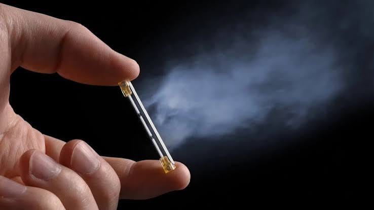
Ion Cooling Engine
Every cooling system ever built for consumer electronics shares one design assumption: to move air, you need a solid surface pushing against it. A blade. A membrane. A piston. The assumption is so old it doesn’t register as an assumption anymore.
It comes with hard limits anyway. A fan’s cooling capacity is bounded by blade diameter, RPM ceiling, bearing life, and the noise generated by turbulence and friction working together. Silicon has scaled past what those limits comfortably allow, more transistors, higher clocks, tighter thermal envelopes, thinner chassis, and fans have had to spin faster to keep up. Faster fans are louder and less reliable, which is exactly the wrong direction when devices are being asked to get quieter and thinner at the same time.
Electrohydrodynamic cooling removes the solid surface from the equation entirely. An electric field accelerates charged particles. Those particles drag neutral air along by collision. No blade, no membrane, no bearing, ionized gas doing the mechanical work a motor used to do.
The phenomenon itself is not new. Francis Hauksbee noted “electric wind” effects from charged points as early as 1709; Michael Faraday studied the same behavior in the 1830s without a way to make it useful. Christenson and Möller formalized it as a thrust mechanism in 1967. What’s new is not the discovery, it’s that electrode engineering has finally caught up to a three-century-old observation, close enough that the technology now ships in TDP-rated commercial hardware.
The Physics, From First Principles
- 1 What a Corona Discharge Actually Is
Two electrodes, very different in shape. One sharp, a fine wire or a needlepoint. One blunt, a plate, a mesh, a cylinder. Separate them by a few millimeters to a few centimeters of air, and apply a DC potential across the gap, typically 3–15 kV.
Here is the subtlety that makes the whole device possible. The average field across the full gap sits far below air’s dielectric breakdown strength, roughly 3 MV/m at sea level. But the field isn’t uniform. It concentrates near the sharp electrode the way mechanical stress concentrates at the tip of a crack. Close enough to that point, the local field exceeds breakdown even while the bulk gap stays safely under it.
Free electrons already exist in the air in trace amounts, seeded by cosmic rays and background radioactivity. In that small high-field pocket, they get accelerated hard enough between collisions to knock additional electrons off neutral N₂ and O₂ molecules. Each ionizing collision produces a positive ion and a fresh free electron. That electron accelerates too, and ionizes more molecules. The multiplication is exponential, a Townsend avalanche, the same mechanism, at a drastically smaller scale, behind lightning.
The result, in a positive corona, is a thin glowing sheath of ionized air clinging to the emitter, continuously shedding positive ions into the drift region toward the collector.
1.2 The Drift Region: Where the Wind Actually Gets Made
A positive ion born at the edge of the corona sheath drifts toward the grounded collector, pulled by the same field that made it. Its velocity follows a simple relation:
v_ion = μ · E
μ is ion mobility, roughly 2 × 10⁻⁴ m²/(V·s) for positive ions in air, an order-of-magnitude figure that shifts with humidity, temperature, and species. E is the local field strength. Structurally, it’s Ohm’s law wearing a different costume: mobility here plays the role conductivity plays in a wire.
The ion doesn’t drift through empty space. It shares the region with a population of neutral molecules large enough that it’s effectively swimming through a sea of them. The exact ratio depends on current and geometry rather than any fixed number, but the imbalance is what matters. Collision after collision, the ion hands off a sliver of its momentum to a molecule that had been sitting still. One collision, alone, is nothing. Billions of them, compounding across the drift length, become a wind.
You are not moving ionized air. You are moving ordinary, neutral air, using a small fraction of ionized air as the hand that pushes it.
1.3 The Force Equations: Quantifying Thrust
Momentum conservation in the drift region gives the net EHD force per unit electrode length:
F_EHD = (I / μ) · d_eff
It is discharge current per unit length, μ is ion mobility, d_eff is an effective distance integrated across the electrode’s surface geometry. Call this the engineer’s equation, not the physicist’s, d_eff stands in for electrode curvature and space-charge density effects that don’t collapse into a clean closed form for arbitrary shapes. It’s what you reach for when sizing a device, not what you’d defend in a derivation.
What it tells you immediately: thrust scales with the current-to-mobility ratio. Not voltage. Voltage only sets the ceiling on how much current you can push before arcing or ozone production take over. Current is the driver; voltage is just the permission slip.
The complete balance subtracts drag:
T = F_EHD − F_D
F_D is drag on the collector, imposed by the very airflow the device generates, a propeller taxed by its own wake. Since F_D scales with wind velocity, and velocity scales with roughly the square root of current, net thrust rises sub-linearly. Push harder, gain less.
Engineers call the resulting efficiency θ (N/W), the EHD analog of CFM-per-watt on a fan datasheet. θ falls as F_EHD climbs. There is no escaping this trade in ionic cooling any more than there is in a mechanical fan; the difficulty simply relocates, from bearings and blade aerodynamics to electrode geometry and plasma chemistry.
1.4 Why Geometry Beats Voltage
A single needle emitter concentrates enormous fields at one point and wastes the rest of its own surface. An array, many fine points, a serrated strip, spreads current density across a larger effective area, multiplying total ion output without pushing any single point past its breaking threshold.
This is the lever that actually moved. Recent electrode geometries report roughly a tenfold gain in electricity-to-airflow conversion over earlier corona-wind attempts. Not a voltage record. Not a new material. A differently shaped piece of metal, arranged so the same field does more collision work per volt. Every architecture in Part II, emitter arrays, DBD surfaces, multi-stage stacks, descends from this one fact: in EHD cooling, shape carries more of the burden than power.
Real Devices: How this becomes a cooling product
2.1 The standard DC Corona architecture
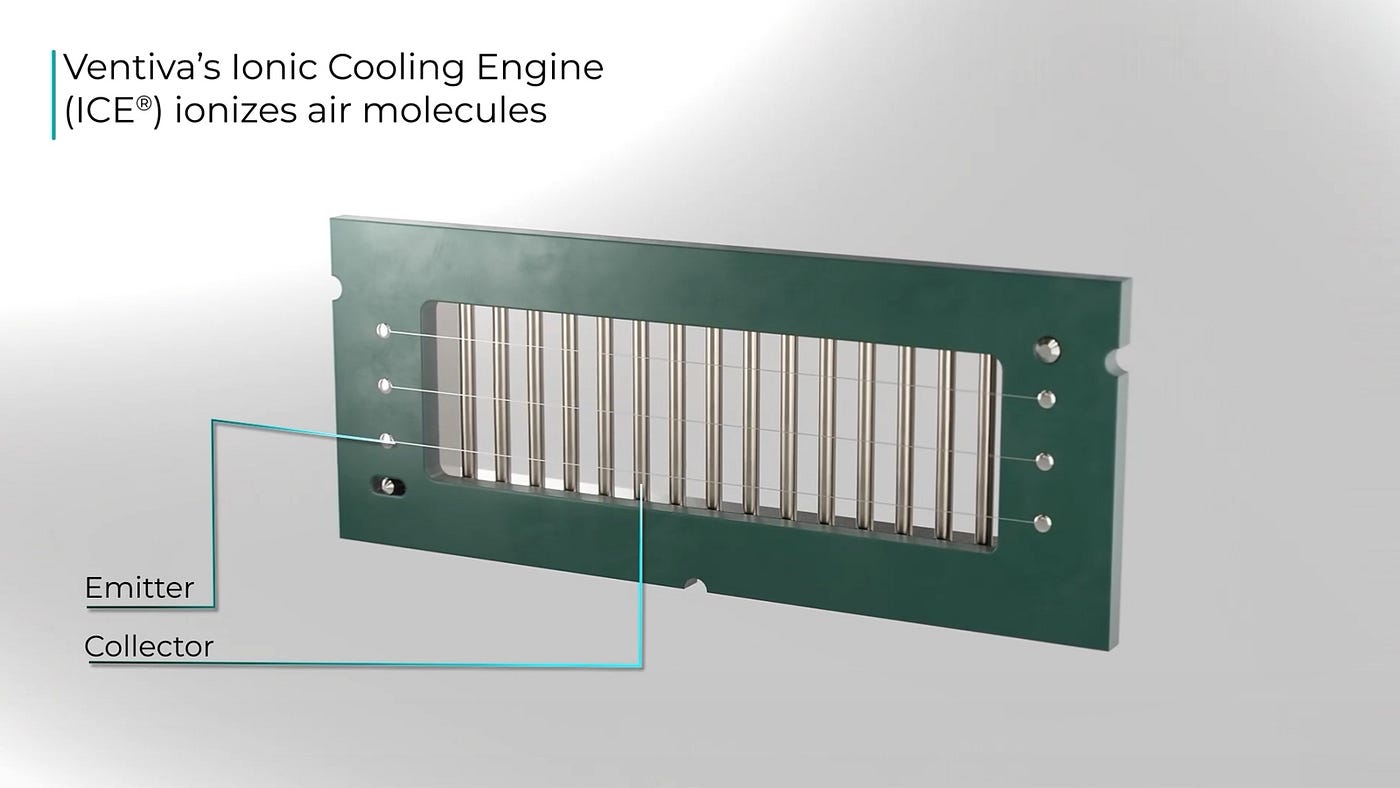
Every subsystem in a laptop-class module exists to protect or exploit that same emitter geometry. The high-voltage generator, a boost converter stepping device-level voltage into the multi-kV range corona onset demands, has one job beyond producing the field: fitting inside a chassis a few millimeters thick. Nontrivial, but secondary. The real center of gravity is the emitter array, deliberately not a single needle, because a needle is precisely the geometry that wastes the electrode’s own potential.
The grounded collector does double duty: completing the circuit, ducting the resulting airflow across the heat sink. The thermal controller, modulating voltage against sensed junction temperature, is where EHD earns its first unambiguous edge over a fan, output adjusts electrically, instantly, with none of the spin-up lag that governs how fast a spinning mass can respond to a thermal spike.
2.2 The DBD Variant: A Sibling Technology
A related approach swaps the open air gap for a dielectric barrier discharge actuator: electrodes separated by a thin dielectric layer, driven by AC instead of DC. The result is a sheet of surface plasma that pushes air along the actuator’s surface rather than across an open gap.
In 2026, this variant was mounted directly on an NVIDIA Jetson Orin Nano at Computex, cooling the module across its full 7–25 W range, including its 25 W “Super Mode”, and reaching steady state in roughly ten minutes. A real edge-AI chip, not a heated test plate.
2.3 Who’s Actually Building This
Every figure in this section is a company’s claim about its own product, worth saying before the numbers, not after.
Ventiva’s Ionic Cooling Engine is rated, by Ventiva, up to roughly 100 W, pitched as a direct fan replacement for lightweight, vibration-sensitive devices. Ionic Wind, the Empa/ETH spin-off behind the tenfold efficiency claim in 1.4, demonstrated at CES 2026 and closed pre-seed funding that March. YPlasma’s DBD approach is what powered the Jetson demonstration above.
None of these numbers have been reproduced by an independent lab under controlled conditions, as far as the public record shows, a distinction that matters more here than in most technology reporting, since thermal-ceiling specs are exactly the kind of number that softens under third-party testing.
Benchmarking Against the Alternatives
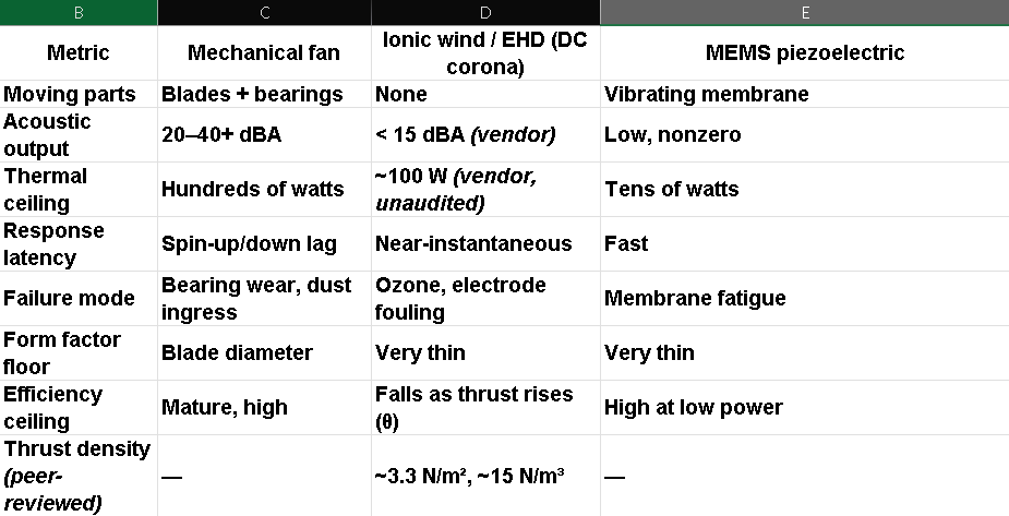
Vendor specs sit above the line; independently published physics sits below it. A reader shouldn’t have to guess which is which.
A comparison worth sitting with: at 3.3 N/m², an EHD array would need roughly the wing area of a small aircraft to lift a housecat. This is not a propulsion technology for anything larger than the air inside a laptop, and that’s precisely the niche it was never trying to leave.
What’s Still Unsolved
Ozone. Unavoidable, chemically, ionizing oxygen-containing gas produces it as a matter of course. What’s condition-dependent is how much: yield rises with current density, rises in dry air, and runs lower in positive coronas than negative ones, though the size of that polarity gap shifts with electrode material rather than holding as a fixed ratio. Outside, it’s background noise. Sealed inches from a face, it’s a constraint every company above has to engineer around, through electrode material, polarity, sometimes catalytic scrubbing. A fan needs none of this.
The airflow ceiling. Low absolute airspeed is the reason three centuries of documented “electric wind” never left the lab until now. Geometry broke the ceiling. Voltage never did.
Fouling. The mechanism depends on a precisely shaped high-field tip. Dust distorts the field. This is a genuinely different failure mode than a worn bearing, and nobody has run it for the number of dusty years that would prove it out.
The tradeoff you can’t skip. θ falls as thrust rises. There is no version of this technology where you simply add current and get fan-competitive output for free, only multi-stage arrays and better geometry, layered carefully.
What a skeptic would say. The honest counterargument is that EHD may be permanently capped below the thermal loads that matter most, a 500 W desktop GPU is not a 25 W edge module, and nothing in the current force equation suggests geometry alone closes that gap. Thrust density scales with electrode area, and electrode area is exactly what a thin laptop chassis won’t give you more of.
The gap in the equation itself. d_eff is a stand-in for curvature and space-charge effects that resist a clean closed form. Full analytical models handle specific geometries more rigorously, at the cost of the simple intuition the approximate equation offers. Rigor against usability, a small version of the same tension running through the rest of this piece.
Where This Actually Lands First
Not the data center. The comparison in Part III settles that: hundreds of watts for mechanical systems against roughly 100 W, vendor-claimed, for the best EHD hardware available. The near-term home is anywhere where silence and thinness outrank raw thermal headroom, thin laptops, fanless edge-AI modules, sealed enclosures where intake vents would otherwise be the design’s weak point.
Three centuries separate Hauksbee’s curious observation from a chip cooling itself in a Computex demo booth. Nothing about the underlying physics changed in that span, the avalanche, the mobility, the force balance were all knowable from the start. What took three hundred years was building a piece of metal precise enough to make the effect useful rather than merely observable. That’s the pattern worth remembering the next time an old, well-understood phenomenon looks like it has nothing left to give: sometimes physics was never the bottleneck. The manufacturing was.
This account reflects the public record as of July 2026, in a space moving fast enough that today’s vendor figures are a snapshot, not a ceiling.
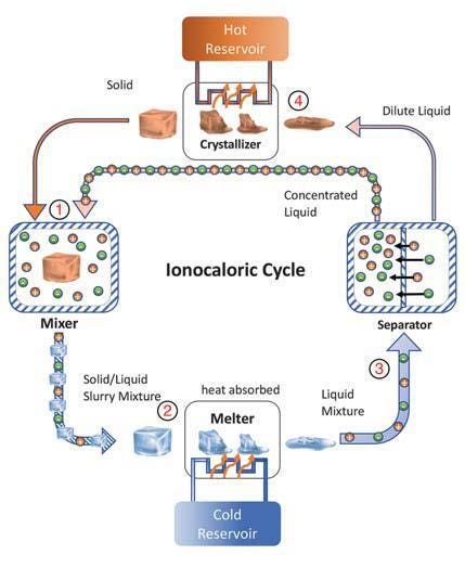
Working
References;
1. Gilmore, C. K. & Barrett, S. R. H. (2015). Electrohydrodynamic thrust density using positive corona-induced ionic winds. Proceedings of the Royal Society A, 471(2175).
2. Kim, C. et al. (2020). Analytical model for electrohydrodynamic thrust. Proceedings of the Royal Society A, 476(2241).
3. Loeb, L. B. (1965). Electrical Coronas: Their Basic Physical Mechanisms. University of California Press.
4. Corke, T. C., Enloe, C. L. & Wilkinson, S. P. (2010). Dielectric barrier discharge plasma actuators for flow control. Annual Review of Fluid Mechanics, 42.
5. Chang, J. S., Lawless, P. A. & Yamamoto, T. (1991). Corona discharge processes. IEEE Transactions on Plasma Science, 19(6).
메타데이터
- post_id
- 70986acb0ce4
- slug
- the-ion-cooling-engine-anatomy-of-a-fanless-machine-70986acb0ce4
- url
- https://medium.com/no-time/the-ion-cooling-engine-anatomy-of-a-fanless-machine-70986acb0ce4
- canonical_url
- https://medium.com/no-time/the-ion-cooling-engine-anatomy-of-a-fanless-machine-70986acb0ce4
- author_url
- https://medium.com/@aashishhhhh
- status
- ok
- fetched_at
- 2026-07-10 13:32:34