How to work with a Mifare DESFire EVx NFC tag on an ESP32 with PN532 reader (Starter tutorial part…
This is part 2 of the tutorial — here I explain the communication with the Mifare DESFire EVx tag in detail. I’m strongly recommending to…
How to work with a Mifare DESFire EVx NFC tag on an ESP32 with PN532 reader (Starter tutorial part 2)
This is part 2 of the tutorial — here I explain the communication with the Mifare DESFire EVx tag in detail. **I’m strongly recommending to read part 1 first, as I’m referring to some explanations made there.**
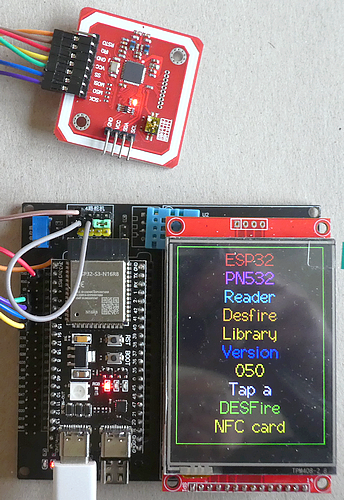
In **part 1 I explained the necessary Hard- and Software, the basics of the DESFire tags and all theoretical stuff to understand those NFC tags, in part 2 (this part) the communication with the card is shown. These are the topics of the tutorial:**
- the basic communication method DF_BasicTransceive
- Get Free Memory of the tag
- Get Version of the tag
- Get More Data command
- Create an Application on the tag
- Select an Application on the tag
- Create a Standard Data file with Free Access Rights within the new application
- Error code overview
- Get File Settings
- Write to a file with Free Access Rights
- Read from a file with Free Access Rights
- Error Code overview
- Summary
Update Nov. 20th 2025: To work with the library with as few errors as possible, it is necessary to modify the Arduino_PN532 library (file “Adafruit_PN532.cpp”) in two places. Firstly, the read and write buffer (“PN532_PACKBUFFSIZ”) must be increased from 64 bytes to 255 bytes. The second change concerns the timeout in the inDataExchange method, which needs to be increased from 1000 milliseconds to 5000 milliseconds. My GitHub repository has a subfolder “Adafruit_PN532_modified” where I provide the modified version (as of version 1.3.4).
The basic communication method DF_BasicTransceive
This is the place where all communication between our sketch and the Adafruit_PN532 library is done. I put it in a method, because that way I can easily get the send and response data for a printout when logging:
ESP32_DESFire::DF_StatusCode ESP32_DESFire::DF_BasicTransceive(byte* sendData, byte sendLen, byte* backData, byte* backLen) {
  ESP32_DESFire::DF_StatusCode result;
  bool success;
  DF_StatusCode statusCode;
  byte bLen = 255;
  if (COMM_DEBUG_PRINT) {
    Serial.printf("Send length %d\n", sendLen);
    printHex(sendData, sendLen);
    Serial.println("");
  }
  success = nfcLib->inDataExchange(sendData, sendLen, backData, &bLen);
  if (COMM_DEBUG_PRINT) {
    Serial.printf("Recv length %d\n", bLen);
    printHex(backData, bLen);
    Serial.println("");
    *backLen = bLen;
    return DF_STATUS_OK;
  } else {
    *backLen = 0;
    return DF_STATUS_ERROR;
  }
}
In the end, it uses the “inDataExchange” method of the PN532 library to send the command and receive a response. If the communication was successful (important: not the result of the command) it returns a “DF_STATUS_OK” to the calling method.
Get Free Memory of the tag
As this is the first command we are running, I’m explaining it in detail; the following commands are less intensive.
byte sendData[5];
sendData[0] = 0x90;                     // CLA
  sendData[1] = DESFIRE_GET_FREE_MEMORY;  // CMD 0x6E
  sendData[2] = 0x00;                     // P1
  sendData[3] = 0x00;                     // P2
  sendData[4] = 0x00;                     // Le
  byte backData[61];
  byte backLen = 61;
  DF_StatusCode statusCode;
  statusCode = DF_BasicTransceive(sendData, sizeof(sendData), backData, &backLen);
  if (statusCode != DF_STATUS_OK)
    return statusCode;
  if (backLen < 2)
    return DF_WRONG_RESPONSE_LEN;
  if (backData[backLen - 2] != 0x91 || backData[backLen - 1] != 0x00)
    return DF_InterpretErrorCode(&backData[backLen - 2]);
  if (backLen != 5)
    return DF_WRONG_RESPONSE_LEN;
  memcpy(backRespData, backData, backLen - 2);
  *backRespLen = backLen - 2;
  return DF_STATUS_OK;
We are defining an array of 5 bytes; the first byte is set to the class 0x90h, followed by the DESFire command 0x6Eh. The next two parameters are set to 0x00h, followed by the “Le” parameter that is usually 0x00h as well. You may notice that the “Lc” parameter is missing — this is due to the fact that there is no additional data to send to the PICC.
The card is responding with 5 bytes in total, and the response is of two parts:
Recv length 5
 80 00 00 91 00
The first three bytes (0x800000h) is the remaining (“free”) memory on the card. It is a 3 byte number, the Lowest significant byte is at the beginning (“LSB” order). To get the numerical value, need to multiply and add the single bytes:
0x80h = 128d * 1   = 128
0x00h = 0d * 256   =   0
0x00h = 0d * 65536 =   0
                     ---
Sum                  128 bytes
The free memory is 128 bytes.
The second two bytes are very important when analyzing the response: the best response we could get is “0x9100h”, as this tells us: the requested command was successful. All other responses need to get analyzed before proceeding with the next step(s). These two bytes are named “Status Bytes”.
Congratulations: you mage your first communication with the DESFire EVx tag.
Get Version of the tag
I’m explaining this command, as it is useful to examine which NFC card was presented to the reader. It is important to distinguish between different card types, as older card types may not run some commands available on newer cards.
The send array is 5 bytes long as before but with a different command: DESFIRE_GET_VERSION (0x60h). This is how the log data is displayed:
Get Version
Send length 5
 90 60 00 00 00
Recv length 9
 04 01 01 33 00 18 05 91 AF
You will notice, that the last byte of the response is “0xAFh” instead of “0x00h”. This is the awaited response that is positive — this is not an error information. You can spell “AF” like “Awaiting Following Data”, meaning the card wants to send more data. The question arises: “why does the card does not send all data in one response” ? The answer is simple: in former times, the (read) buffer in the NFC Reader was small, and the module could not read more data, so the response is chunked in 3 peaces. So we send a:
Get More Data command
Again, we send a 5 bytes long sequence with DESFIRE_GET_MORE_DATA (0xAFh):
Get More Data
Send length 5
 90 AF 00 00 00
Recv length 9
 04 01 01 03 00 18 05 91 AF
Again, the card is notifying us that more data will follow, and we send the command again:
Send length 5
 90 AF 00 00 00
Recv length 16
 04 35 68 DA 05 1A 90 20 82 62 30 30 34 23 91 00
Now, the data is complete as we received a “0x9100h” response.
In total, we received 28 bytes of data (9–2, 9–2 and 16–2 bytes) that give us detailed information about the tag tapped. If you want to know what information is coded in the response, I’m recommending to take a close look at the “NTAG 424 DNA” data sheet, pages 58ff.
Create an Application on the tag
At this point, we create our first application on the card. The data sheets don’t help us further, because the “NTAG424 DNA” and “DESFire light” are delivered with a pre-installed application, including some files that cannot get deleted and created. But the “**EV1 protocol”** document is a good source for getting help, on pages 8 ff you find:

The “Create Application” command is “0xCAh”, followed by the Application Identifier (“AID”), a “Key setting byte” and an “App setting byte”. And beware, this is the naked command structure and not the “wrapped” one! But it is not too hard to build the command we need for sending:
byte aid[3] = { 0x56, 0x78, 0x9A };
byte keySettings = 0x0F;
byte appSettings = 0x85;  // first nibble '8' = AES, second nibble '5' = 5 keys
byte sendData[11];
sendData[0] = 0x90;                        // CLA
sendData[1] = DESFIRE_CREATE_APPLICATION;  // CMD DESFIRE_SELECT_APPLICATION (0xCA)
sendData[2] = 0x00;                        // P1
sendData[3] = 0x00;                        // P2
sendData[4] = 0x05;                        // Lc
sendData[5] = aid[0];
sendData[6] = aid[1];
sendData[7] = aid[2];
sendData[8] = keySettings;
sendData[9] = appSettings;
sendData[10] = 0x00;  // Le
We define the AID (3 bytes), the key settings and app settings. For more details about the key settings, you take a close look at the “Protocol EV1” document at page 7. The value “0x0Fh” b.t.w. is the default value.
The app settings is a byte, and in hex encoding expressed by two characters:
byte appSettings = 0x85;
                     |  '8' = upper nibble
                      | '5' = lower nibble
The ‘8’ in the upper nibble is the coding for AES-128 keys, the ‘5’ in the lower nibble will create an application with 5 (AES) keys.
Please note: for this tutorial, we don’t need any keys, but there might be a next tutorial that includes the usage of keys.
This time, the ‘Lc’ parameter in sendData[4] is not null but “0x05h”, meaning that 5 data bytes are following:
aid[0], aid[1], aid[2], keySettings, appSettings: each 1 byte long, 5 in total
Send length 11
 90 CA 00 00 05 56 78 9A 0F 85 00
Recv length 2
 91 00
This looks great, and we send the same command with equal data again:
Send length 11
 90 CA 00 00 05 56 78 9A 0F 85 00
Recv length 2
 91 DE
This time, the response is indeed an error: “0xDE” is the code for a “Duplicate Error” situation. And yes, the card is right, we tried to create an already existing application again. This error code is more of a warning than an actual error.
Let’s create our first file of type “Standard Data file”:
Create a Standard Data file with Free Access Rights within the new application
The “EV1 Protocol” PDF is our friend again, and the command structure is as follows:

Beneath the “Create Standard Data file” command (“0xCDh”) we do have 4 parameters with a total of 7 bytes of data:
Structure of a Create Standard Data file command:
command: 0xCDh
file number: e.g. 0x01h
Communication settings byte: 0x00h for PLAIN communication
Access right byte 1: 0xEEh
Access right byte 2: 0xEEh
File size: 3 bytes in LSB order, e.g. 0x20 00 00h [give 32 bytes]
For this tutorial, we are using the simplest possible options and that is the PLAIN communication mode and a “Free Access rights” (both explained in part 1 of the tutorial).
The last parameter is an LSB encoded value for the file size; as our file should be 32 bytes long, we have to encode this as “0x200000h”.
The ‘Lc’ parameter gets “0x07h” and now we are sending it to the card:
Create a Standard Data file with Free Access Rights
Send length 13
 90 CD 00 00 07 01 00 EE EE 20 00 00 00
Recv length 2
 91 9D
Ups, something got wrong, but what was the reason ?
Error Code Overview
The “EV1 Protocol” gives valuable information on page 5 about most status/error codes when working with a DESFire EVx card., e.g. “0x9Dh” is a “Permission denied” error.
The reason for this error is simple: we created an application and then created a file, but as we did not select the application we are still in the Master Application where files are not permitted. As an intermediate command, I explain the
Select an Application on the tag
This is like the change to a subfolder on your hard disc, and we just need the AID as parameter:
byte sendData[9];
sendData[0] = 0x90; // CLA
sendData[1] = DESFIRE_SELECT_APPLICATION; // INS 0x5A
sendData[2] = 0x00; // P1
sendData[3] = 0x00; // P2
sendData[4] = 0x03; // Lc
// copy the AID in parameter
for (i = 0; i < 3; i++) {
  sendData[5 + i] = aid[i]; // 3 byte AID
}
sendData[8] = 0x00;
This is the complete log file:
Send length 9
 90 5A 00 00 03 56 78 9A 00
Recv length 2
 91 00
Okay, as we got a “success” response, we are running the Create File command again:
Create a Standard Data file with Free Access Rights
Send length 13
 90 CD 00 00 07 01 00 EE EE 20 00 00 00
Recv length 2
 91 00
This time we are lucky and have created a new Standard Data file with a file size of 32 bytes.
Analogous to the creation of an application, when running the “create file” command a second time the response is “0x91DEh” as the file already exists.
Now our environment is ready, and we can write to the file and read the written data back. Before that, we execute a very useful command:
Get File Settings
The response to the “Get File Settings” command informs us about some basics of the file. Just run the command and we discuss the data received:
Get File Settings
Send length 7
 90 F5 00 00 01 01 00
Recv length 9
 00 00 EE EE 20 00 00 91 00
Beneath the two status bytes at the end, there are 7 data bytes. Please note: the structure depends on the file type and possibly on additional features that are enabled (e.g. Secure Dynamic Messaging (SDM)).
Response structure for Get File Settings (00 00 EE EE 20 00 00):
00 = file type = Standard Data file
00 = file options = Plain communication mode
E | E = Read&Write Access right | Change Access key right
E | E = Read Access right       | Write Access right
20 00 00 = file size in LSB encoding = 32 bytes
This information is important when reading an unknown application. With this data, you authenticate with the right key and reserve enough space for the input or output buffer. The library has a “FileSettingsDebugPrint” method that helps us a little bit:
File Settings for file 01
File Type         : 00 (Standard Data File)
File Options      : 00
File Comm Mode    : PLAIN
File RW/CAR AccRg : EE
File R/W    AccRg : EE
File Size         : 32
Write to a file with Free Access Rights
Now we come to the two most important commands you are here for: write some data to a DESFire EVx card and read them back. The NTAG424DNA data sheet (pages 75 ff) helps us in building the command sequence:

All rights go to NXP B.V.
This time, the command sequence is quite longer as we are sending data to write on the tag. Our data to write is stored in ‘sendData’ and the ‘length’ is ‘sizeof(sendData)’ :
// byte sendData[32] is '0x 01 02 03 04 05 06 07 08 09 0A 0B 0C 0D 0E 0F 10 11 12 13 14 15 16 17 18 19 1A 1B 1C 1D 1E 1F 20'
byte fileNumber 0x01;
byte offset = 0x00; // 0x00 = 0 = start writing at the beginning
byte length = sizeof(sendData); // 0x20 = 32 bytes = complete file
byte* sendData2 = new byte[length + 13];
sendData2[0] = 0x90;                     // CLA
sendData2[1] = DESFIRE_WRITE_DATA_FILE;  // CMD 0x8D
sendData2[2] = 0x00;                     // P1
sendData2[3] = 0x00;                     // P2
sendData2[4] = 7 + length;               // Lc
sendData2[5] = fileNo;                   // FileNo
sendData2[6] = offset;                   // Offset in LSB encoding
sendData2[7] = 0x00;                     // (Offset)
sendData2[8] = 0x00;                     // (Offset)
sendData2[9] = length;                   // Length in LSB encoding
sendData2[10] = 0x00;                    // (Length)
sendData2[11] = 0x00;                    // (Length)
memcpy(&sendData2[12], sendData, length);
sendData2[length + 12] = 0x00;  // Le
The array that is sent to the tag is dynamic and depends on the amount of data, so for 32 bytes of data it is (32 + 13) = 45 bytes long. The same applies to the ‘Lc’ value — it is of dynamic value (32 + 7) = 39 bytes (0x27h).
The offset value define the position within the file where the data is stored, in our case the offset is ‘0’. The same applies to the length, this is the amount of data we are writing. An important note about this implementation: both “offset” and “length” fields are 3 bytes long fields encoded in LSB, but as we only use 1 byte from a variable we can use only offsets and length of 255 in maximum. We use this limitation as within our tutorial we just use small files, but for longer files you need to implement a method to convert an integer to an LSB byte sequence.
After the third length parameter, I’m copying the sendData array to the sendData2 array, followed by the ‘Le’ parameter.
A note on the ‘offset’ and ‘length’ pair: if you would try to write the 32 bytes of data (length = 32) at offset = 1, you will receive a “Boundary Error” as the end of the data is ‘outside’ of the defined size of the file.
Let’s see what happens when sending this package to card:
Write to a file with Free Access Rights
Generated data length 32 data: 01 02 03 04 05 06 07 08 09 0A 0B 0C 0D 0E 0F 10 11 12 13 14 15 16 17 18 19 1A 1B 1C 1D 1E 1F 20
Send length 45
 90 8D 00 00 27 01 00 00 00 20 00 00 01 02 03 04 05 06 07 08 09 0A 0B 0C 0D 0E 0F 10 11 12 13 14 15 16 17 18 19 1A 1B 1C 1D 1E 1F 20 00
Recv length 2
 91 00
We got a positive response from the tag and we now try to read the data back.
Read from a file with Free Access Rights
Again, the NTAG424DNA data sheet is most helpful to us. Beginning at page 73, the complete command and response structure is explained in detail:

All rights go to NXP B.V.
byte fileNumber 0x01;
byte offset = 0x00; // 0x00 = 0 = start reading at the beginning
byte length = 0x20; // 0x20 = 32 bytes = complete file
byte sendData[13];
sendData[0] = 0x90;              //CLA
sendData[1] = DESFIRE_READ_DATA; // CMD 0xAD
sendData[2] = 0x00;              // P1
sendData[3] = 0x00;              // P2
sendData[4] = 0x07;              // Lc
sendData[5] = fileNumber;        // fileNo
sendData[6] = offset;            // offset in LSB encoding
sendData[7] = 0x00;              // offset byte 2
sendData[8] = 0x00;              // offset byte 3
sendData[9] = length;            // length in LSB encoding
sendData[10] = 0x00;             // length byte 2
sendData[11] = 0x00;             // length byte 3
sendData[12] = 0x00;             // Le
This is the communication result:
Send length 13
 90 AD 00 00 07 01 00 00 00 20 00 00 00
Recv length 34
 01 02 03 04 05 06 07 08 09 0A 0B 0C 0D 0E 0F 10 11 12 13 14 15 16 17 18 19 1A 1B 1C 1D 1E 1F 20 91 00
Read Data response length 32 data: 01 02 03 04 05 06 07 08 09 0A 0B 0C 0D 0E 0F 10 11 12 13 14 15 16 17 18 19 1A 1B 1C 1D 1E 1F 20
The response is the complete content of our file — 32 bytes with ascending values and 2 status bytes. Great !

Error Code overview
At this time we received some of the errors codes from the tag, but there are some more of them. The sketch folder contains a “Status_Codes.md” file with all common Error Codes for your convenience.
Summary
It is not too hard to work with a modern Mifare DESFire EVx in an ESP32 environment and connected PN532 NFC Card reader.
Update November 24th., 2025
There is a new article available: “**How to read and write large data files on a Mifare DESFire EVx NFC tag on an ESP32 with PN532 reader**”.
Source code of the apps
You find the complete code of the app in my GitHub repository.
Happy coding !
메타데이터
- post_id
- 7bcfbafd326f
- slug
- how-to-work-with-a-mifare-desfire-evx-nfc-tag-on-an-esp32-with-pn532-reader-starter-tutorial-part-7bcfbafd326f
- url
- https://medium.com/@androidcrypto/how-to-work-with-a-mifare-desfire-evx-nfc-tag-on-an-esp32-with-pn532-reader-starter-tutorial-part-7bcfbafd326f
- canonical_url
- https://medium.com/@androidcrypto/how-to-work-with-a-mifare-desfire-evx-nfc-tag-on-an-esp32-with-pn532-reader-starter-tutorial-part-7bcfbafd326f
- author_url
- https://medium.com/@androidcrypto
- status
- ok
- fetched_at
- 2026-07-25 23:39:52