Graph Data Modelling: A Functional Framework for Getting It Right
Using Oil & Gas subsurface data as a real-world case study
Graph Data Modelling: A Functional Framework for Getting It Right
Using Oil & Gas subsurface data as a real-world case study
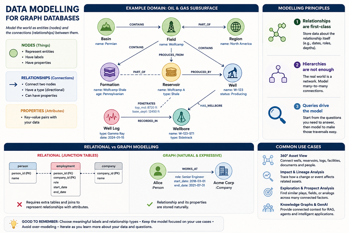
AI Generated
The modelling principles in this post are informed by the graph database modelling chapter in Learning Neo4j by Rik Van Bruggen, extended with domain-specific application to the Oil & Gas subsurface world.
When approaching a new database, most people rely on familiar mental models. Experience with relational databases leads to thinking in tables; experience with document stores leads to thinking in nested objects. However, these instincts can hamper and even mislead you when working with graph databases.
Graph databases require a fundamentally different approach to data. Fortunately, this approach follows a clear framework. This post develops that framework from first principles, using Oil & Gas subsurface data to illustrate each concept with practical examples.
By the end, you will have three core principles for graph data modeling, a practical example to adapt to your domain, and the insight to assess your own models.
Why graph modelling matters in the age of GenAI
Before discussing the mechanics of graph modelling, it is important to consider why this topic is especially relevant today, past traditional database engineering concerns.
Software systems are evolving in how they answer questions. Large language models allow scalable querying of unstructured text, and vector databases make semantic search efficient. However, as organizations deploy production AI systems, a key issue emerges: semantic similarity alone is insufficient.
Vector search is exceptionally good at finding things that mean something similar. Ask “which documents discuss reservoir pressure?” and a vector search will surface the most semantically relevant results. But it cannot answer:
- Which wells penetrate formations connected to a specific reservoir?
- Which documents describe assets owned by the same operator as this well?
- Which entities are connected through a chain of regulatory, geological, or operational relationships?
These are not similarity questions; they are traversal questions that demand explicit, stored relationships. This is precisely what a graph database offers.
GraphRAG — where graphs and LLMs meet
The emerging pattern that brings these two worlds together is called GraphRAG (Graph Retrieval-Augmented Generation). In a standard RAG system, a user question is embedded as a vector, similar document chunks are retrieved, and an LLM generates an answer from those chunks. It works well for factual lookups. It breaks down when the answer requires connecting multiple entities across explicit relationships.
GraphRAG improves this process by first traversing the knowledge graph to collect structured context — recognizing relevant nodes, their connections, and the meaning of their relationships — then providing this context to the LLM along with or instead of raw document chunks. This approach produces answers that are both semantically plausible and structurally grounded.
In the O&G subsurface domain, this is not a theoretical benefit. Consider a question like:
“Summarise the production history of all wells that penetrate the Arab-D formation in the Ghawar field and have active regulatory permits.”
Vector search retrieves documents that appear relevant. Graph traversal, however, identifies the exact wells, their formation penetrations, permit status, and production records, all with full provenance. The LLM then reasons over precise, structured context rather than relying on semantically similar text.
Graphs as the connective tissue of agentic systems
Agentic AI systems, where an LLM plans and executes multi-step tasks, encounter comparable challenges on a larger scale. An agent navigating from a business question through regulatory records, geological data, and operational history cannot rely solely on similarity. It requires a clear map of connections.
A well-designed knowledge graph provides this map. Nodes represent entities the agent can reason about, relationships define traversable paths, and properties on those relationships supply the required context for each step.

This is why graph modelling has become more than a database engineering discipline. The way you model your graph determines which questions your AI system can answer. A poorly designed graph — one that hides relationships in properties, applies strict hierarchies, or omits cross-cutting connections — will limit any AI system built on it, regardless of the LLM’s capabilities.
The principles in this post address both AI-ready data infrastructure and effective graph database design. Let us explore them.
A quick primer on the domain
You do not need to be a petroleum engineer to follow this post. The following context will make the examples meaningful.
The subsurface in Oil & Gas refers to the geological layers beneath the earth’s surface where hydrocarbons — oil and gas — are trapped. Exploring for and producing those hydrocarbons involves a chain of entities:
- A Basin is a large geological depression where sediment has accumulated over millions of years, creating the conditions for oil and gas to form. The Permian Basin in Texas, the North Sea, the Arabian Platform.
- A Field is an area where hydrocarbons have been found in commercial quantities. It has both a geological meaning (a trap containing oil or gas) and an administrative one (a licence boundary, an operator).
- A Reservoir is the specific rock unit that stores the hydrocarbons — porous, permeable rock saturated with oil or gas. One field can produce from multiple reservoirs. One reservoir can underlie multiple fields.
- A Formation is a named, mappable rock unit defined by its age, rock type, and origin. Reservoirs are typically expressed in specific formations.
- A Well is the legal and commercial entity — the registered borehole with a unique identifier, a spud date, and a regulatory status.
- A Wellbore is the physical borehole. A single well can have multiple wellbores — the original hole plus any sidetracks drilled later to reach new targets or bypass problems.
- A Well Log is a continuous measurement recorded along the length of a wellbore — gamma ray, resistivity, sonic, density — that tells geologists what rock types and fluids are present at each depth.
This outlines the domain. Next, we will examine how to model it.
Principle 1: Relationships are first-class citizens, not just connectors
Start with something familiar
Think about a person who worked at a company. You want to record that fact. Simple enough. But the moment someone asks — when did they start? when did they leave? what was their role? — you have a problem.
Those three pieces of information do not belong on the Person. A person works at many companies over a career, each with different dates and roles. They do not belong on the Company either, for the same reason. They belong on the connection itself — on the act of employment between those two specific things.
This is what it means for a relationship to carry data. The connection is not simply a pointer from one thing to another. It is a meaningful piece of information in its own right.
In everyday language we already think this way, naturally:
Alice worked at Acme Corp from 2018 to 2021 as a Senior Engineer.
The worked at relationship carries the dates and role; the sentence is incomplete without them. However, most databases make it difficult to store data in this manner.
Here is what this looks like as a graph. The dates and the role do not live on either circle — they live on the arrow between them:

The arrow represents more than a pointer; it is a first-class data element.
Why relational databases struggle here
In a relational database, you have two tables: person and company. You cannot put start_date or role directly on the line connecting them — there is no such concept. So the standard solution is to create a third table whose only purpose is to represent the connection:
CREATE TABLE employment (
    person_id   INT REFERENCES person(person_id),
    company_id  INT REFERENCES company(company_id),
    role        TEXT,
    start_date  DATE,
    end_date    DATE
);
This approach works, but note the consequence: the employment table is not a real-world entity. Alice is a real person, and Acme is a real company, but employment exists solely because the database cannot store data on a connection. Queries now require joining three tables instead of two, and developers must interpret the purpose of this table.
This workaround is known as a junction table. It is common in relational schemas — user_role, product_tag, order_item — all following the same pattern: a table created because the model cannot directly express the intended relationship.
How a graph database handles this
In Neo4j, a relationship between two nodes is a first-class thing — it has a type, a direction, and it can hold properties directly. There is no junction table because there is no need for one:
CREATE (alice:Person  {name: 'Alice'})
CREATE (acme:Company  {name: 'Acme Corp'})
CREATE (alice)-[:WORKS_AT {
role: 'Senior Engineer',
start_date: date('2018-03-01'),
end_date: date('2021-07-31')
}]->(acme)The WORKS_AT relationship represents employment. Its properties — role, start date, end date — describe the specific employment event between Alice and Acme. If Alice joins another company, a new WORKS_AT relationship with different properties is created. The data resides precisely where it belongs: on the connection.
Querying it feels natural too:
// What roles has Alice held, and where?
MATCH (alice:Person {name: 'Alice'})-[job:WORKS_AT]->(company:Company)
RETURN company.name AS company,
       job.role     AS role,
       job.start_date AS from,
       job.end_date   AS to
ORDER BY job.start_date
This approach uses a single pattern with no joins. The query closely mirrors the original question.
Now apply this to O&G — and see why it really matters
The employment example is simple, but the Oil & Gas subsurface domain provides a more compelling case. Here, data on the connection is not only convenient but scientifically essential.
A wellbore is a physical borehole drilled into the earth. As it goes deeper, it passes through different rock layers. Each rock layer is a formation — a named, mappable geological unit. When a wellbore passes through a formation, four things must be recorded:
- At what depth did it enter the formation?
- At what depth did it exit?
- What fluid was found — oil, gas, water, or nothing?
- How many metres of productive rock (called net pay) did it encounter?
Here is the scenario before addressing those questions:

Now ask yourself the same question as before: where do these four values belong?
Not on the Wellbore node — A single wellbore passes through dozens of formations as it drills deeper. If you put top_md (the entry depth) on the wellbore, which formation are you referring to? The wellbore enters the Arab-D carbonate at 2,100m and the Hith anhydrite at 2,430m. Both cannot be top_md on the same node without specifying which formation — and the moment you have to specify which formation, you have admitted the value belongs on the connection, not the node.
Not on the Formation node — The Arab-D formation is penetrated by hundreds of wellbores across the Ghawar field, each entering at a different depth depending on where it was drilled and how the rock tilts underground. There is no single top_md for Arab-D — there are as many entry depths as there are wellbores that have penetrated it.
The four values belong on the connection — on the act of one physical thing passing through another. In Neo4j:
CREATE (wb:Wellbore  {name: 'Ghawar-A001/ST1'})
CREATE (fm:Formation {name: 'Arab-D', lithology: 'carbonate'})
CREATE (wb)-[:PENETRATES {
top_md: 2100.0,
base_md: 2430.0,
fluid_encountered: 'oil',
net_pay_m: 68.5
}]->(fm)The PENETRATES relationship represents the geological penetration event. Its properties describe the specific encounter — not the wellbore or formation in general, but the exact instance when this borehole passed through this rock layer at a particular depth and encountered a specific fluid.
And now a geologist’s question becomes a straightforward query:
// Which wellbores found oil in Arab-D, and how much net pay did each find?
MATCH (wb:Wellbore)-[p:PENETRATES]->(fm:Formation {name: 'Arab-D'})
WHERE p.fluid_encountered = 'oil'
RETURN wb.name AS wellbore,
p.top_md AS entered_at_m,
p.net_pay_m AS net_pay_m
ORDER BY p.net_pay_m DESCThis query supports real exploration decisions by ranking wells based on the productive rock found in a target formation. In a relational system, this would require a junction table and multiple joins. In a graph, it is a single traversal that closely matches the original question.
The design rule
If a property describes the connection between two things — not either thing on its own — it belongs on the relationship.
A practical test: if you are unsure, try assigning the property to each node. If it only makes sense when referencing both nodes, it belongs on the relationship.
Some examples to anchor the pattern:

In each case, the property describes the act of connection, not either entity independently. It should therefore reside on the relationship.
Principle 2: The hierarchy trap — when trees fail you
The instinct to build a tree
Every domain has a natural top-down structure. Countries contain cities. Companies contain departments. In Oil & Gas, the natural reading of the domain looks like this:

Each level contains the one below it, which aligns with how we typically explain the domain: “a basin is inside a region, a field is inside a basin.” As a result, the initial Neo4j model often reflects this structure:
CREATE (r:Region {name: 'Middle East'})
CREATE (b:Basin {name: 'Rub al Khali'})
CREATE (f:Field {name: 'Ghawar', operator: 'Saudi Aramco'})
CREATE (w:Well {uwi: 'SA-GHWR-A001', spud_date: date('1951-05-12')})
CREATE (wb:Wellbore {name: 'SA-GHWR-A001/ST1', md_total: 2843.5})
CREATE (wl:WellLog {log_type: 'GR', run_date: date('1952-03-01')})CREATE (r)-[:CONTAINS]->(b)
CREATE (b)-[:CONTAINS]->(f)
CREATE (f)-[:HAS_WELL]->(w)
CREATE (w)-[:HAS_WELLBORE]->(wb)
CREATE (wb)-[:HAS_LOG]->(wl)This model works for simple queries such as “list all wells in Ghawar” or “which logs does this wellbore have?” The hierarchy is not incorrect, but it is incomplete. Incompleteness in a data model often becomes apparent at critical moments.
Where the hierarchy breaks
Problem 1: Some entities simply refuse to have one parent.
A horizontal well in a tight formation is often drilled from a surface location in one field, but its horizontal section — the part that actually produces — extends into a different field. The hierarchy demands one parent. The geology does not cooperate.
Furthermore, a well can have two valid “parents”: the field to which it is administratively assigned and the basin where it is geologically located. These are distinct facts with different purposes. The hierarchy merges them into a single CONTAINS chain, losing this important distinction.
Problem 2: Some entities live at multiple levels of the hierarchy at once.
Look at the hierarchy above and try to find where Reservoir fits. It is not contained by a field — one reservoir often underlies multiple fields. It is not contained by a basin — reservoirs can cross basin boundaries. It is not contained by a well — multiple wells produce from the same reservoir.
A reservoir is a geological entity that connects to the administrative hierarchy at multiple points simultaneously:
- A field produces from a reservoir
- A wellbore produces from a reservoir (at specific perforation depths)
- A reservoir is expressed in a specific formation
There is no single correct place for Reservoir in the hierarchy. Forcing it into the tree either results in duplication — one node per field — or omission. Both are incorrect, yet both are common when teams begin graph modelling with a hierarchy.
Problem 3: The hierarchy has no place for the connections from Principle 1.
As established in Principle 1, the connection between a wellbore and a formation carries geological data such as entry depth, exit depth, fluid encountered, and net pay. However, in the hierarchy above, Formation does not exist as a node because it does not fit into a single level of the tree.
The fix: treat the hierarchy as a sub-graph, not the whole model
The hierarchy is valid and should remain. Administrative containment from Region to Well is both real and useful. The mistake is treating it as the entire model.
The correct approach is to retain the hierarchy where it accurately represents containment, and to model all other connections as cross-cutting relationships between independent nodes:
// ── Nodes ─────────────────────────────────────────────────────────────────────CREATE (r:Region {name: 'Middle East', code: 'ME'})
CREATE (b:Basin {name: 'Rub al Khali', area_km2: 650000})
CREATE (f:Field {name: 'Ghawar', discovery_year: 1948, operator: 'Saudi Aramco'})
CREATE (fm:Formation {name: 'Arab-D', age: 'Upper Jurassic', lithology: 'carbonate'})
CREATE (res:Reservoir {name: 'Arab-D Reservoir', fluid_type: 'oil', api_gravity: 34.0})
CREATE (w:Well {uwi: 'SA-GHWR-A001', name: 'Ghawar-A001', spud_date: date('1951-05-12')})
CREATE (wb:Wellbore {name: 'SA-GHWR-A001/ST1', md_total: 2843.5, status: 'producing'})
CREATE (wl:WellLog {log_type: 'GR', run_date: date('1952-03-01'), top_md: 1800.0})// ── Administrative hierarchy — still valid, keep it ───────────────────────────
CREATE (r)-[:CONTAINS]->(b)
CREATE (b)-[:CONTAINS]->(f)
CREATE (f)-[:HAS_WELL]->(w)
CREATE (w)-[:HAS_WELLBORE]->(wb)
CREATE (wb)-[:HAS_LOG]->(wl)// ── Cross-cutting relationships — what the hierarchy was hiding ───────────────// A well is located in a basin (geological fact, independent of field boundary)
CREATE (w)-[:LOCATED_IN]->(b)// A field produces from a reservoir (administrative ↔ geological link)
CREATE (f)-[:PRODUCES_FROM]->(res)// A reservoir is expressed in this formation
CREATE (res)-[:EXPRESSED_IN]->(fm)// A wellbore penetrates a formation — with geological data on the relationship
CREATE (wb)-[:PENETRATES {
    top_md:            2100.0,
    base_md:           2430.0,
    fluid_encountered: 'oil',
    net_pay_m:         68.5
}]->(fm)// A wellbore produces from a reservoir — with completion data on the relationship
CREATE (wb)-[:PRODUCES_FROM {
perf_top_md: 2150.0,
perf_base_md: 2390.0,
completion_date: date('1952-06-15')
}]->(res)// A well log was measured within a specific formation interval
CREATE (wl)-[:MEASURED_IN]->(fm)Here is what that looks like as a graph — compare it to the clean tree from Model v1:

The original six-node hierarchy remains intact as the left spine of the diagram. Reservoir and Formation now exist as independent nodes, connected to the hierarchy at all relevant points. The graph is no longer a tree — which is the correct structure.
The design rule
A hierarchy is a valid sub-graph, not a complete model.
If you find yourself asking “where does this entity fit in the tree?”, consider it a warning. Entities that connect to multiple hierarchy levels or to elements outside the tree should be modelled as independent nodes with their own relationships, not forced into a single parent category.
A practical test: if removing a node from your hierarchy does not disconnect two entities with a direct real-world relationship, those entities should have a direct relationship in the model. Avoid forcing entities to communicate through a parent when a direct connection exists.
Principle 3: Design for queries, not for taxonomy
The trap of building a “correct” model
The first two principles get your structure right. This third one determines whether your structure is actually useful.
A common trap is believing the model is complete after identifying nodes, establishing relationships, and assigning properties. The model may appear accurate, with a sound hierarchy and cross-cutting relationships.
However, a data model is not merely a domain description; it is an engine for answering key questions. A model that cannot efficiently address important queries is inadequate, regardless of its accuracy.
This principle requires a shift in approach: start with the questions you need to answer, then work backwards to identify the necessary entities.
Start with user stories
Before writing any schema, write down the five questions your system most needs to answer. In natural language, without thinking about database structure. For the subsurface domain, those questions might be:
- Which wellbores have penetrated the Arab-D formation, and how much net pay did each find?
- Which wells in the Rub al Khali basin have never tested the Arab-D formation?
- What logs are available for the Arab-D interval across all wellbores in the Ghawar field?
- Which reservoirs does a given wellbore produce from, and at what depths?
- Give me the complete geological and administrative context for a single well.
These questions highlight that Formation and Reservoir must be first-class nodes. Questions 1, 2, 3, and 5 cannot be answered if Formation is only a property on a wellbore. Question 4 is unanswerable if Reservoir is not a node.
The questions did not merely validate the model — they shaped it. Formation and Reservoir were included in the schema because the questions required them.
Turning questions into Cypher
Let us walk through each question and see how the model supports it — and what would break if the model were the simple hierarchy from Principle 2’s v1.
Question 1: Wellbores that penetrated Arab-D, ranked by net pay
MATCH (wb:Wellbore)-[p:PENETRATES]->(fm:Formation {name: 'Arab-D'})
RETURN wb.name             AS wellbore,
       p.top_md            AS top_md_m,
       p.net_pay_m         AS net_pay_m,
       p.fluid_encountered AS fluid
ORDER BY p.net_pay_m DESC
This query requires Formation as a node and PENETRATES as a relationship with net_pay_m as a property. In the hierarchy model, these elements do not exist, making the query impossible.
Question 2: Untested wells — exploration target identification
This is the kind of question that drives real exploration decisions: which wells in a basin have never tested a specific formation? It sounds negative — “find things that do NOT have a connection” — which is where graph databases particularly shine.
MATCH (b:Basin {name: 'Rub al Khali'})<-[:LOCATED_IN]-(w:Well)
WHERE NOT EXISTS {
    MATCH (w)-[:HAS_WELLBORE]->(wb:Wellbore)-[:PENETRATES]->(:Formation {name: 'Arab-D'})
}
RETURN w.name AS well,
       w.uwi  AS uwi
ORDER BY w.name
The NOT EXISTS subquery in Cypher clearly expresses the absence of a path. In SQL, the equivalent requires a LEFT JOIN with WHERE IS NULL or a NOT IN subquery, both of which are less readable and more error-prone on large datasets. In a graph, the concept of "no path exists between these two things" is straightforward.
Question 3: Log availability for a formation across a field
A petrophysicist running a regional correlation study needs to know: for every wellbore in this field that has penetrated the target formation, what log types are available?
MATCH (f:Field {name: 'Ghawar'})-[:HAS_WELL]->(w:Well)
     -[:HAS_WELLBORE]->(wb:Wellbore)
     -[:HAS_LOG]->(wl:WellLog)
     -[:MEASURED_IN]->(fm:Formation {name: 'Arab-D'})
RETURN w.name       AS well,
       wb.name      AS wellbore,
       wl.log_type  AS log_type,
       wl.run_date  AS run_date
ORDER BY w.name, wl.log_type
The traversal follows a logical path through the graph — field to well to wellbore to log to formation — in a clear and readable pattern. There is no ambiguity, and no mental translation is needed between the question and the query.
Question 4: Reservoir connections for a single wellbore
MATCH (wb:Wellbore {name: 'SA-GHWR-A001/ST1'})-[pf:PRODUCES_FROM]->(res:Reservoir)
RETURN res.name           AS reservoir,
       res.fluid_type     AS fluid,
       pf.perf_top_md     AS perf_top_m,
       pf.perf_base_md    AS perf_base_m,
       pf.completion_date AS completed
ORDER BY pf.perf_top_md
Note that perf_top_md and perf_base_md — the depths at which the wellbore was perforated to connect to the reservoir — are properties of the PRODUCES_FROM relationship. This reflects Principle 1: these depths describe the specific completion event between this wellbore and this reservoir, not either entity independently.
Question 5: Full context for a well — one query
MATCH (w:Well {uwi: 'SA-GHWR-A001'})
OPTIONAL MATCH (w)-[:LOCATED_IN]->(b:Basin)
OPTIONAL MATCH (f:Field)-[:HAS_WELL]->(w)
OPTIONAL MATCH (w)-[:HAS_WELLBORE]->(wb:Wellbore)
OPTIONAL MATCH (wb)-[pen:PENETRATES]->(fm:Formation)
OPTIONAL MATCH (wb)-[:HAS_LOG]->(wl:WellLog)
RETURN w.name                        AS well,
       b.name                        AS basin,
       f.name                        AS field,
       wb.name                       AS wellbore,
       wb.status                     AS wellbore_status,
       collect(DISTINCT fm.name)     AS formations_penetrated,
       collect(DISTINCT wl.log_type) AS available_logs
This single query provides the complete context for a well: administrative details, physical configuration, all penetrated formations, and available log types. In a relational schema, assembling this view typically requires multiple joins and often a pre-materialised view for performance. In a graph, the traversal follows the natural structure of the data.
When a new question changes the model
The most important insight from this principle is that your model is not finished when it looks correct — it is finished when it answers your questions efficiently. New questions sometimes reveal that the model needs to change.
Suppose a new question arrives: “Which wells share the same formation, and could therefore be in pressure communication with each other?”
Your current model can answer this — find all wellbores that penetrate a given formation and trace back to their wells — but it is a two-hop traversal that might become slow at scale. A query-driven modeller might consider adding a direct SHARES_FORMATION relationship between wells as a shortcut, trading some write complexity for read speed.
Alternatively, they may determine that the current traversal is sufficient and that adding a shortcut is unnecessary. The key point is that the question drives the decision. The model evolves in response to real use cases, not theoretical correctness.
The design rule
Write your five most important queries before you commit to a model. If any query requires an entity or relationship that does not exist in your schema, your schema is not done.
Most data models are built top-down: entities first, relationships second, queries last. In graph modelling, reverse this order. Start with the questions you need to answer, work backwards to determine what to store, and let queries shape the model — even if this requires revisiting earlier decisions.
Pulling it together: a complete framework
The three principles build on each other and should be applied in sequence:
Principle 1 — Relationships carry data. Before creating a junction table or adding a property to a node, ask whether the value describes the connection rather than either connected thing. If yes, put it on the relationship. This is the most syntactically unfamiliar principle for anyone coming from a relational background, but it is also the most immediately rewarding.
Principle 2 — Hierarchies are sub-graphs, not complete models. A tree is a valid way to represent containment. But real domains have entities that cross hierarchy levels, connect to multiple parents, or relate to things outside the tree entirely. When an entity does not fit cleanly into the hierarchy, that is a signal it needs to be its own node with its own relationships — not a forced fit into a single parent slot.
Principle 3 — Design for queries, not taxonomy. A model that accurately describes a domain but cannot efficiently answer key questions is inadequate. Write your essential queries before finalising the schema; these queries will reveal missing nodes, relationships, and properties that domain analysis alone may overlook.
The O&G example is specific, but the framework transfers. Here is how the same three principles appear in two other domains:
Healthcare — patient treatment
- Principle 1: A patient
RECEIVEDa drug, withdosage,start_date,end_date, andprescribing_reasonon the relationship — not on the patient, not on the drug. - Principle 2: A
Conditiondoes not belong underPatientin a hierarchy. The same condition appears across thousands of patients, multiple specialties, and many treatment protocols. It is its own node. - Principle 3: “Which patients with condition X have NOT received treatment Y?” is the query that makes
Conditionnecessary. Without writing that query first, you might never add it to the schema.
Supply chain — logistics network
- Principle 1: A supplier
SHIPS_TOa warehouse, withlead_time_days,cost_per_unit, andcontract_expiryon the relationship. The lead time is a property of that specific supplier-warehouse lane, not of either party. - Principle 2: A
Productdoes not live under any single supplier or warehouse — it moves through the network and connects to many nodes at once. It is its own node. - Principle 3: “Find the fastest supply path from raw material to customer with total lead time under 14 days” is a graph traversal. Writing that query first tells you immediately that
lead_time_daysmust be on theSHIPS_TOrelationship — because that is what the traversal will sum.
Common mistakes — and how to spot them early
Even with a clear framework, a few patterns trip people up consistently.
Multiplying node properties instead of adding a relationship. If you find a node with properties like top_md_arab_d, top_md_hith, top_md_hanifa — depths for different formations — that is the classic sign those values should be on PENETRATES relationships to separate Formation nodes. When properties start multiplying because they are always paired with a reference to something else, move them to a relationship.

Building a hierarchy and calling it a graph. If your Neo4j model is a tree with no cross-cutting relationships, you are using a graph database as an expensive tree store. The value of a graph database appears when entities connect to multiple other entities in semantically distinct ways. If everything has exactly one parent and no node appears at more than one level, revisit Principle 2.
Creating nodes for things that should be relationships. The opposite mistake is also common: creating a Penetration node to sit between Wellbore and Formation instead of using a PENETRATES relationship with properties. If the intermediate node has no properties of its own and will never be queried directly — only traversed through — it adds an unnecessary hop to every query. Ask whether the intermediate concept needs to exist independently, or whether it is simply a connection with data.
Ignoring the dense node problem. The Arab-D formation across the Ghawar field is penetrated by thousands of wellbores. A Formation node connected to 10,000 PENETRATES relationships is a potential performance bottleneck — every traversal touching that node must scan all 10,000 relationships before filtering. The mitigation is awareness early: consider partitioning very-high-degree nodes by sub-interval, geographic area, or time period before the data grows into the problem.
What to take away
Graph data modelling is not hard, but it requires unlearning some habits that relational databases spent decades reinforcing.
The three principles in this post are a framework for that unlearning:
- Put data where it belongs — sometimes that is on a relationship, not a node.
- Let the domain’s real shape emerge — hierarchies are starting points, not destinations.
- Let your questions build your schema — accuracy without query-ability is not enough.
The Oil & Gas subsurface domain is a good test case precisely because it resists simplification. Its entities cross administrative and geological boundaries, its relationships carry scientifically essential data, and its most important questions are deeply networked. A framework that works here will work in most domains you encounter.
And if you are building AI systems on top of your data — RAG pipelines, agentic workflows, knowledge graphs for LLMs — the quality of your graph model is the quality ceiling for every answer those systems can produce. A relationship that exists in your domain but is missing from your graph is a question your AI system will never be able to answer correctly, no matter how capable the model.
Start with your relationships. Question your hierarchies. Write your queries first.
The Cypher examples in this post are written for Neo4j 5.x. All O&G domain values are illustrative. Future post will extend this model to handle time-versioned interpretations and fault connectivity — two patterns that push all three principles to their limits.
메타데이터
- post_id
- 9064c2af4a6d
- slug
- graph-data-modelling-a-functional-framework-for-getting-it-right-9064c2af4a6d
- url
- https://levelup.gitconnected.com/graph-data-modelling-a-functional-framework-for-getting-it-right-9064c2af4a6d
- canonical_url
- https://levelup.gitconnected.com/graph-data-modelling-a-functional-framework-for-getting-it-right-9064c2af4a6d
- author_url
- https://medium.com/@ladvishal1985
- status
- ok
- fetched_at
- 2026-08-02 19:17:18