How to Achieve 1,000Hz Signal Integrity: Bypassing PCB Noise and 1.5%
If you have ever tried to build a high-speed motion tracking system, you already know the nightmare: sensor drift, data corruption, and…
How to Achieve 1,000Hz Signal Integrity: Bypassing PCB Noise and 1.5% Error Margins via Advanced Guarding
If you have ever tried to build a high-speed motion tracking system, you already know the nightmare: sensor drift, data corruption, and high-frequency noise
securing flawless 3D trajectory reconstruction at 1,000Hz.
When dealing with 9-axis IMU sensors sampling at 1,000Hz, many software engineers immediately jump into optimizing sensor fusion codes — tweaking Kalman filters or tuning complementary filter algorithms. However, if the raw input data itself is contaminated, you can never escape the absolute rule of engineering: “Garbage In, Garbage Out.”
At 1,000Hz, the fight to compress your systemic error margin to $\le$ 1.5% is not won in the IDE. It is won on the physical PCB layout.
Here is how we solved the high-frequency digital noise problem on the hardware architecture level for CAST9.
1. The Real Culprit: Digital Cross-Talk and Jitter
When high-speed digital data lines (SPI’s SCLK, MOSI, MISO, or fast $I²C$) run parallel to analog sensor supply lines or clock signals, electromagnetic cross-talk is inevitable.
As sampling frequency hits 1,000Hz, the tiny parasitic inductance and capacitance of your copper traces begin to distort the signal edges. This distortion triggers packet drops and timing jitter. If your data bytes are corrupted before the MCU even reads them, your 3D trajectory reconstruction algorithms will completely fall apart.
To fix this, we had to rethink our physical layout from scratch using two uncompromising hardware strategies.
2. Strategy 1: Implementing Ground Guard Rings for Electrical Isolation
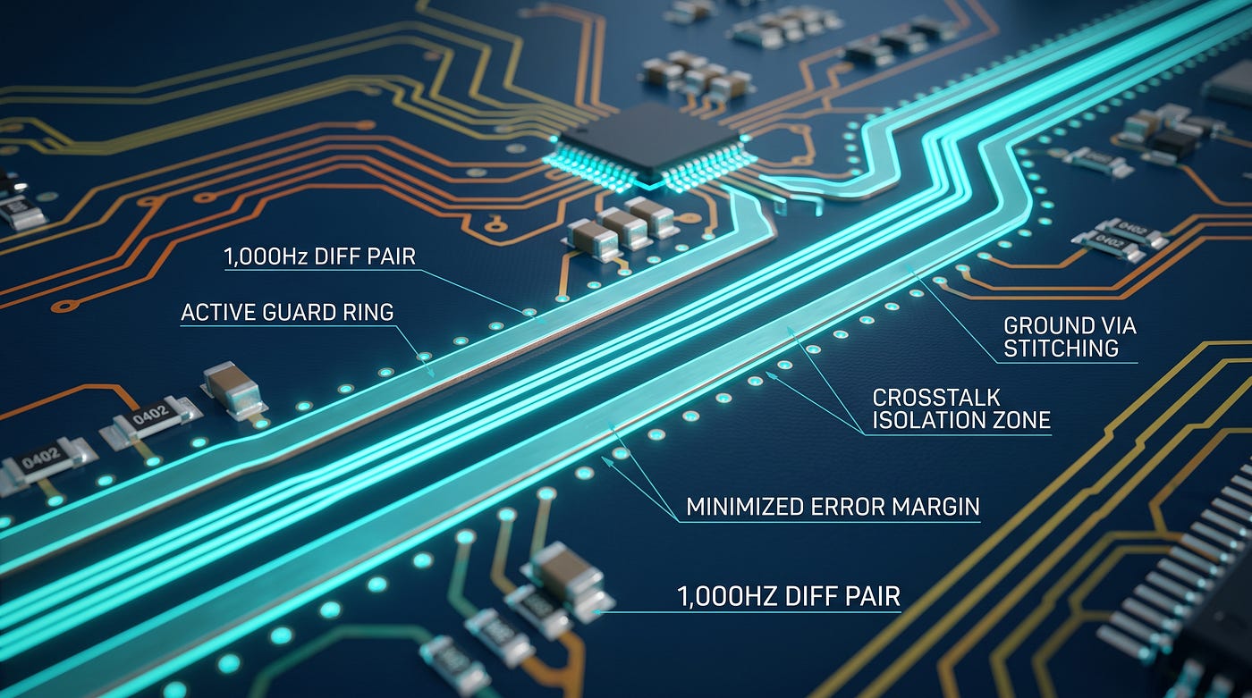
To isolate high-speed data lines from adjacent switching noise, we implemented solid Guard Rings.
- Physical Isolation: We routed copper ground (GND) traces on both sides of the high-speed SPI data lines, creating a localized, physical shield directly on the routing layer.
- Stitching Vias: We placed stitching vias at tight, regular intervals along the guard rings to bind them immediately to the internal/bottom solid ground planes. This effectively drives the return path’s loop inductance ($L_{loop}$) down to near zero.
- The Result: Any high-frequency EMI emitted from nearby power lines or clock signals gets intercepted by the guard ring and bypassed straight to ground before it can corrupt our critical data signals.
3. Strategy 2: Ultra-Dense MLCC Placement Directly at Sensor Pins
A classic artwork mistake is placing decoupling capacitors (MLCCs) wherever there is open space, a few millimeters away from the IC. At 1,000Hz, that tiny distance creates a trace loop that acts as an antenna for high-frequency ripples.
We enforced a strict layout priority rule: [Main Power Line $\rightarrow$ Via $\rightarrow$ MLCC Pad $\rightarrow$ Sensor Power Pin].
![[Main Power Line — via — MLCC PAD-Sensor Power Pin].](https://miro.medium.com/v2/resize:fit:729/1*_T0xRc7H98ksgjtts5oTtg.png)
[Main Power Line — via — MLCC PAD-Sensor Power Pin].
By routing the current directly through the MLCC pads, we forced high-frequency power rails to clear their ripples right before entering the sensor. This ensured the internal data converters and digital output blocks maintained pristine signal integrity.
Conclusion: Engineering Precedes Software
By optimizing our hardware architecture with strict guard rings and ultra-dense MLCC placement, we completely eliminated the random data spikes that plague high-frequency tracking. This physical layout optimization is what ultimately allowed us to lock down an error margin of under 1.5%, securing flawless 3D trajectory reconstruction at 1,000Hz.
If you are fighting IMU noise, stop rewriting your software filters. Pick up your hardware layout tool, look at your signal traces, and start shielding
📥 Gumroad Call to Action
Looking for the actual implementation details? We have packaged our exact Altium/KiCad artwork templates, Gerber layouts, and oscilloscope signal comparison data sheets into a premium hardware report.
👉 **[Download the 1,000Hz Hardware Signal Integrity Blueprint on Gumroad Now ($29)]**
메타데이터
- post_id
- 90f5a2cd082f
- slug
- how-to-achieve-1-000hz-signal-integrity-bypassing-pcb-noise-and-1-5-90f5a2cd082f
- url
- https://medium.com/@CAST9/how-to-achieve-1-000hz-signal-integrity-bypassing-pcb-noise-and-1-5-90f5a2cd082f
- canonical_url
- https://medium.com/@CAST9/how-to-achieve-1-000hz-signal-integrity-bypassing-pcb-noise-and-1-5-90f5a2cd082f
- author_url
- https://medium.com/@CAST9
- status
- ok
- fetched_at
- 2026-07-20 14:02:25