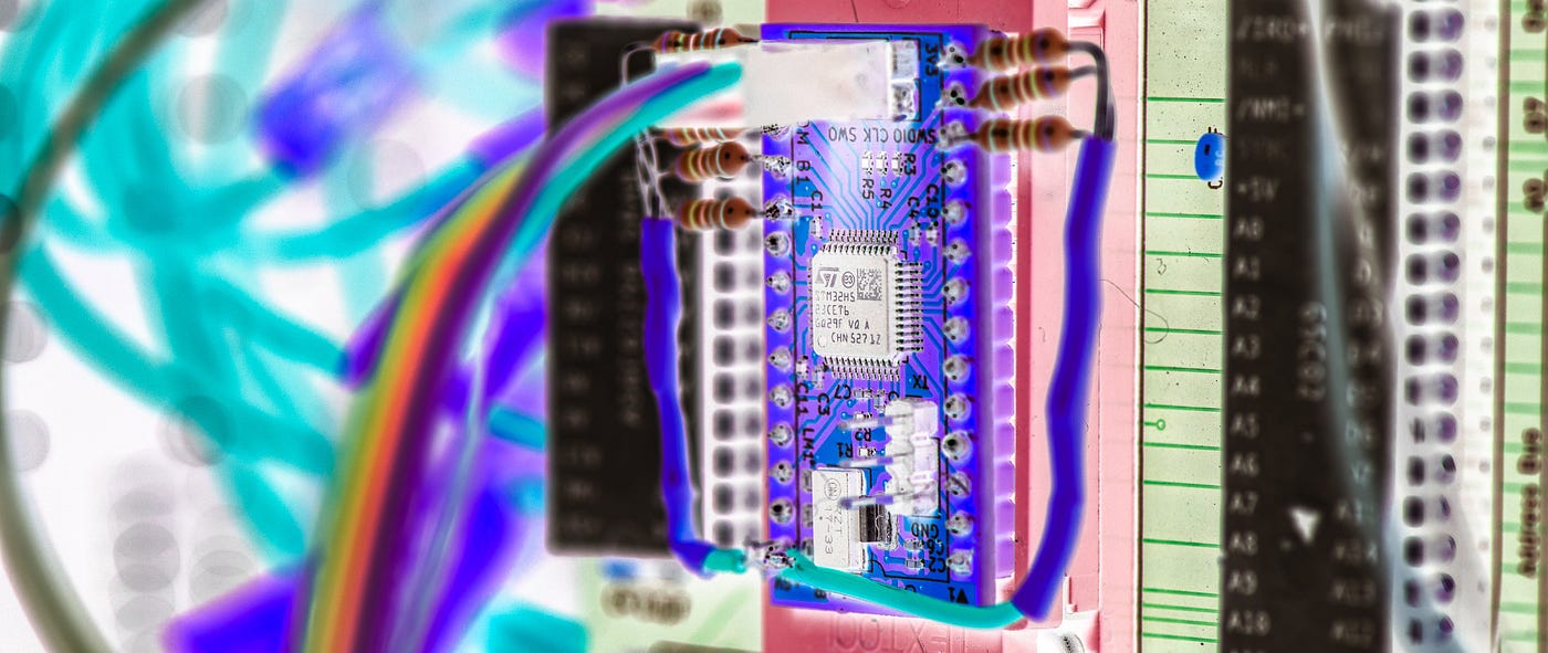
McROM redux: improving the STM32 microcontroller-based ROM emulator
The first version worked in my homebrew computer, although not without persuasion. Let’s see if we can do better.
MICROCONTROLLERS
McROM redux: improving the STM32 microcontroller-based ROM emulator
The first version worked in my homebrew computer, although not without persuasion. Let’s see if we can do better.
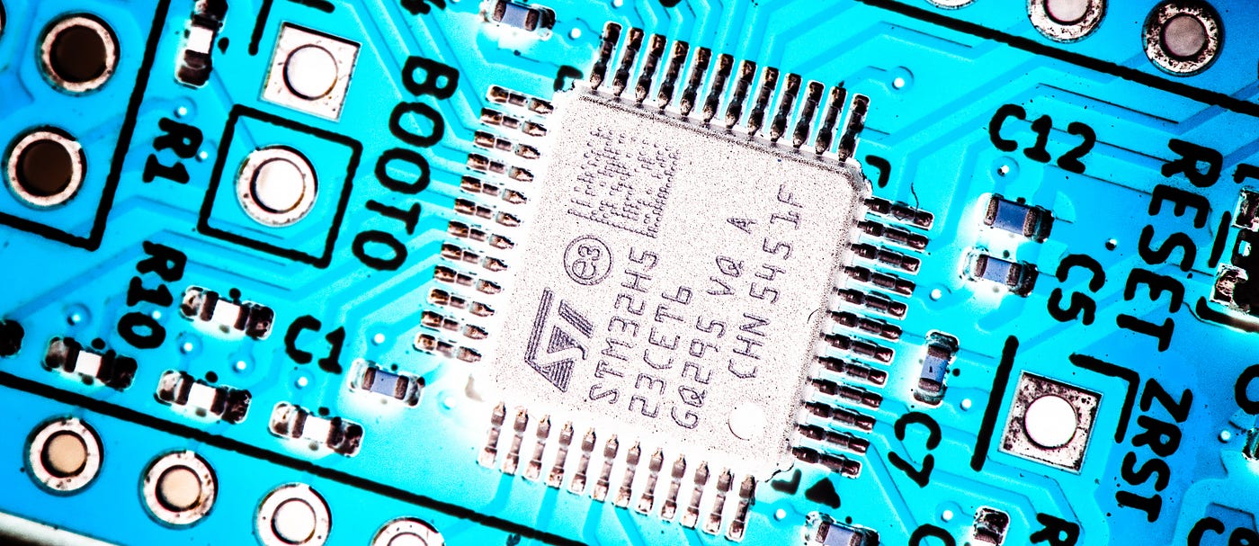
All photographs by the author.
Following the age-old principle of ‘if it ain’t broke, see if you can break it’, I decided to have another crack at the PCB for the McROM, a microcontroller-based replacement for the EEPROM in my Zolatron 65C02 homebrew computer.
The McROM is based on an STM32H523CET6 microcontroller humming along at an impressive 250MHz. It has more than enough GPIOs to handle the address bus, data bus and control signals. The idea was to have a board with the same footprint and pinout as the 28C256 EEPROMs I’m currently using as ROMs in the Zolatron so that I could drop the McROM straight into the socket that already exists on the main processor board. The advantage would be that I can reprogram the device without having to remove it from the Zolatron — indeed, without even having to turn off the computer.
In the first article in this series I detailed the board design and the ideas behind it. In the second article I covered the STM32 firmware and also some of the issues I encountered.
At the end of that second article I had a device that was (mostly) working, and which at least proved the concept. But this was my first STM32 project and, inevitably, there were challenges and mistakes. For one thing, I ended up soldering eight pull-up resistors to the board in a manner that could be politely described as ‘iconoclastic’. But I’m not polite so let’s call it an ugly bodge.

This madness had to end.
Fortunately, PCBWay supports this publication by providing free PCBs, so I took the opportunity to do a respin. Let’s look at what changed.
Trimming the size
Although version 1 of the McROM has more-or-less the same footprint as a 28C256, it turned out to be slightly biased towards the ‘more’ end of that range, in that the board itself was ever so slightly longer than the equivalent chip. I knew this when I designed the PCB and thought it would be fine, which it mostly was. However, that tiny bit of extra length at one end, which was there to make room for a couple of bypass capacitors that accompanied the LM1117 3.3V linear regulator, did present one minor niggle.

The new board. Pretty, no?
On one CPU board, it worked fine. This has a genuine 3M zero insertion force (ZIF) socket. On another copy of the CPU board, however, I’d used a different (a euphemism for ‘cheaper’) design of ZIF socket. Its lever operates laterally across the end of the socket and so fouls on the small overhang on the PCB. It’s not a big deal, but if I’m going to have the ambition of making a drop-in replacement for the 28C256 then these little irritations should not exist. That overhang had to go.
This was made possible in two ways. First, I replaced the LM1117, which has a SOT-223 footprint taking up around 7.3x6.7mm of space, with a TLV75533PDBV which is SOT-23–5 at about 3x3mm. Also, for some reason, I’d specified 0603 (1608 metric) packages for those two bypass capacitors for the regulator when all the other capacitors and resistors on the board were 0402 (1005 metric). This time around, everything is in the smaller package.
No more serial
Then there was the matter of the serial port. Version 1 of the board has one. Version 2 does not. And in one sense I was sorry to see it go.
It’s a reflex action of mine, a kind of development tic, that if a microcontroller on a board has a UART going spare I’ll hook up the TX and RX lines to header pins. A serial port is incredibly useful for debugging, so why not?
Well, the reason why not is that those two header pins, plus a third for a ground connection, can take up an inordinate amount of space on a board that’s only 36.72x18.26mm. My preference is for 2.54mm pitch Dupont headers. And while I could have gone for some kind of header with a finer pitch, this would have made it less easily employable.
In any case, the McROM code has had to be optimised for speed. There really wasn’t any way of incorporating serial communications into the code without impacting its vital functions. It would just introduce delays and jitter and generally complicate matters, and so be useless for analysing issues.
Removing the UART pins does limit the board’s potential for non-McROM projects, which is a shame. But compromises had to be made and eliminating those three header pins freed up a huge tract of board real estate.
Pulling up
The extra space was essential because this version of the board has a new bunch of components.
Remember how I said I’d soldered eight resistors on to the version 1 board? It would be far more respectable to have those on the board itself, almost as if they weren’t a desperate attempt to get things working.
Each data bus pin now has a 4.7kΩ pull-up resistor connected to the 5V supply. This ensures that when the STM32 (which is a 3.3V device) puts a high signal on the line, the voltage jumps to a level that the 5V-based 65C02 recognises as a high. It needs the level to be at least 3.5V and the STM runs out of puff well below that. Luckily, the STM32 pins I selected are all 5V-tolerant, so the pull-ups cause no issue.
That’s eight new devices.
It also came to my attention that the system-wide /READ_EN and /ROM_ENABLE signals had no pull-ups. These are active low signals and are provided by some decoding logic on the Zolatron's main processor board.
/READ_EN goes low when the 65C02's RWB pin is high and the PHI2 clock is high. It's connected to multiple devices, including RAM and the output enable (/OE) pin of the EEPROM.
ROM_ENABLE goes low when address bus lines A14 and A15 are both high. That happens only when the CPU wants to talk to the ROM, which lives in the top 16kB of the memory map.
Until now, I had no problems with these signals potentially floating because after the power-on sequence is complete, the CPU has got its act together and the machine is running, these lines are going to be positively controlled one way or the other.
With the McROM, however, it has its own preparations to do, and I strongly suspected that I was getting timing issues where maybe the STM32 was booted but the rest of the system was still in a ‘just got out of bed’ state. It’s possible that spurious states on /READ_EN and ROM_ENABLE were luring the STM32 into kicking off operations for which the rest of the system wasn't ready. And when the system was ready, the STM32 might have been in the middle of doing something entirely inappropriate.
Getting rid of spurious states is what pull-up resistors were born to do. I chose 4.7kΩ devices to match those on the data bus lines to keep the bill of materials (BOM) simple. The 65C02 would have no trouble pulling those lines low when needed.
In case of emergency
The next two additions were ones I might not need, but are good to have when you do need them.
The first is a simple reset button. This takes the STM32’s NRST pin low. During my experiments with the version 1 board I managed to get the microcontroller into what can only be described as an 'unknown state', in which it would no longer accept my attempts to flash new code. In fact, I did this twice.
The first time I managed to recover by STM32CubeProgrammer and, in the ST-Link configuration set the Mode to ‘Under reset’ and the frequency to something nice and slow, like 480kHz. I ran a wire from GND to the NRST pin on the programming header. Then I clicked on the 'Connect' button STM32CubeProgrammer while almost immediately pulling away the grounding wire.
It was a clumsy technique and I had to try several times, but it finally worked and I went on to use the board successfully again, but it would have been so much easier with a reset button. A search on Mouser produced a suitable button with a reasonably small PTS830 footprint.

The board with its pins and headers in place. The six pins on the right are for programming and debugging the microcontroller. The single pin on the left is for resetting the host machine.
Not so fast
On the other occasion, this technique did not work. With this copy of the board, I think the chip had really got itself into a state.
My code runs a very tight loop in ITCM RAM with interrupts disabled (__disable_irq()) and the SysTick suspended. This could result in the debugger struggling to find a 'gap' to take control of the CPU. However, there was one possible way to recover.
The STM32 has a small, read-only memory area called the System Memory that contains a factory-programmed bootloader. This is separate from the flash code and is guaranteed to work. By pulling the BOOT0 pin high (3.3V) and then toggling the NRST pin the CPU bypasses any glitchy code in the main flash and enters the bootloader. Since the bootloader doesn't disable the debug pins or enter sleep modes, the SWD interface becomes responsive again. At that point you can perform a full chip erase to have a clean start with something like:
STM32_Programmer_CLI -c port=swd -e allThen you disconnect the BOOT0 pin from the 3.3V supply and flash your code as usual. Except, that I couldn't do any of this.
On the PCB, I’d tied BOOT0 directly to ground, thinking I wouldn't need it. And I mean directly—no pull-down resistor. That meant I couldn't just connect a wire from 3.3V to the pin on the STM32 chip. It wouldn't pull it high enough. And I couldn't cut the trace between the pin and the via to ground because it is under the chip. I never did recover that microcontroller.
On the new version of the board, BOOT0 runs to ground via a resistor. It also has a connection to 3.3V via two header pins. Normally, these are not connected, so BOOT0is pulled low. But in an emergency I can put a jumper on the header pins and pull the signal high.

The schematic for the new version.
Back to the beginning
While on the subject of resetting things, the final addition to the board is a pin labelled ZRST. From this I can run a wire to the Zolatron’s reset line, so that the STM32 can reset the whole machine by pulling it low. The plan is that the McROM will hold the Zolatron in reset until it has its trousers on and is good and ready to perform its ROM-like duties.
Currently, after powering on or reflashing the McROM firmware, I have to press the reset button on the Zolatron. It isn’t exactly the most onerous task, but I’m a firm believer in reducing my workload whenever possible.
How’s that working out for you?
The board itself looks great. I’d chosen the red solder mask this time to distinguish it from the earlier (yellow) version. I’d used the PCBWay PCB Assembly service so all the surface-mount components were in place when I got the boards.

There are three ways you can get the orientation of that chip wrong.
One of the things I really like about this service is that, after the boards have been manufacturer but before the components are soldered on, the company emails you with photographs of a hand-assembled test piece. This is so that you can check that all the devices are in the correct orientation. With an LED, for example, that can make the difference between the component working or not working. With other devices, such as power diodes or polarised capacitors, it can make the difference between a working board and a smoking mess.
As it happens, with this board there was only one component where orientation was crucial. This was the microcontroller itself. It’s a 48-pin QFP package, symmetrical in both axes. That means there are three ways of getting it wrong and only one of getting it right.
I assume the Gerber files indicate which pin should go to which pad, but as a safety measure I make sure pin 1 is clearly indicated on the silkscreen (in this instance with a small arrow). When I got the email from PCBWay it was a simple matter to ensure the dot on the chip, which indicates the corner with pin 1, matched up with my arrow. That sort of thing eliminates a lot of anxiety.
Having spent a few blissful moments admiring the soldering and just how damn professional it appears, what with those tiny components so neatly arranged. It looks like something you might buy from a shop (you can’t). Of course, looks can be deceptive; the critical thing is, does it work?
Yes, it does. I’m still not getting the machine to boot properly on power-up and so have to hit that reset button. But I’ve so far not encountered any of the occasional software errors I had before. I have a sneaking suspicion that the pull-ups on ROM_ENABLE and READ_EN are helping out. So I'm calling this mission accomplished, although I dare say I'll still be tweaking the code a little over the months to come.
You can find the code for this project in the McROM repository on GitHub.
*Steve Mansfield-Devine is a freelance writer, tech journalist and photographer. You can find photography portfolio at Zolachrome, buy his books and e-books, or follow him on Bluesky or Mastodon.*
Or you can buy Steve a coffee — it helps keep these projects going.
메타데이터
- post_id
- 942d50eef04d
- slug
- mcrom-redux-improving-the-stm32-microcontroller-based-rom-emulator-942d50eef04d
- url
- https://medium.com/machina-speculatrix/mcrom-redux-improving-the-stm32-microcontroller-based-rom-emulator-942d50eef04d
- canonical_url
- https://medium.com/machina-speculatrix/mcrom-redux-improving-the-stm32-microcontroller-based-rom-emulator-942d50eef04d
- author_url
- https://medium.com/@mansfield.devine
- status
- ok
- fetched_at
- 2026-06-09 15:37:30