How I Built an Event-Driven Integration Platform for Healthcare Using MuleSoft
By Naresh Podichetty | Solution Architect | MuleSoft | Enterprise Integration | Healthcare IT
How I Built an Event-Driven Integration Platform for Healthcare Using MuleSoft
By Naresh Podichetty | Solution Architect | MuleSoft | Enterprise Integration | Healthcare IT
This article is based on my hands-on experience designing and delivering the Major healthcare product data management platform for a leading global Life Sciences company. The architecture patterns, challenges, and lessons shared here are drawn from real enterprise implementations.
1. The Problem Nobody Talks About in Healthcare IT
Healthcare organisations sit on mountains of data — product catalogues, clinical records, sales interactions, customer master data — spread across dozens of disconnected systems. The result? Teams manually reconciling spreadsheets at 11 PM, delayed drug launches due to data inconsistencies, and compliance teams losing sleep over audit trails.
When I was brought in to architect the integration platform for a major Life Sciences organisation, the landscape looked like this:
- MDM (Master Data Management) held the golden record for product data
- OCE Sales managed field force interactions and customer engagements
- MCM (Multichannel Marketing) drove digital campaigns and customer journeys
- LEXI was a custom internal application needing to orchestrate all of the above
These four systems were islands. No real-time sync. No event awareness. No single source of truth flowing across them.
My mandate: build an integration platform that makes these systems talk to each other in real time, without tight coupling, and at enterprise scale.
This is how I did it.
2. Why Event-Driven Architecture?
Before I get into the solution, let me explain why I chose an event-driven approach over the traditional point-to-point or batch-based integration.
The Traditional Approach — And Why It Fails
Most enterprises default to one of two patterns:
Point-to-point integration: System A calls System B directly via an API. Simple, but creates a tangled web as systems grow. Change System B’s API and everything breaks.
Batch processing: Data is synced on a schedule — every hour, every night. Fine for reporting but catastrophic when a field rep needs up-to-date product information before a doctor’s appointment.
Neither works for modern healthcare where data freshness and system resilience are non-negotiable.
The Event-Driven Advantage
Event-Driven Architecture (EDA) flips the model. Instead of System A calling System B, System A announces what happened: “A product record was updated.” Any system interested in that event — OCE Sales, MCM, LEXI — subscribes and reacts independently.
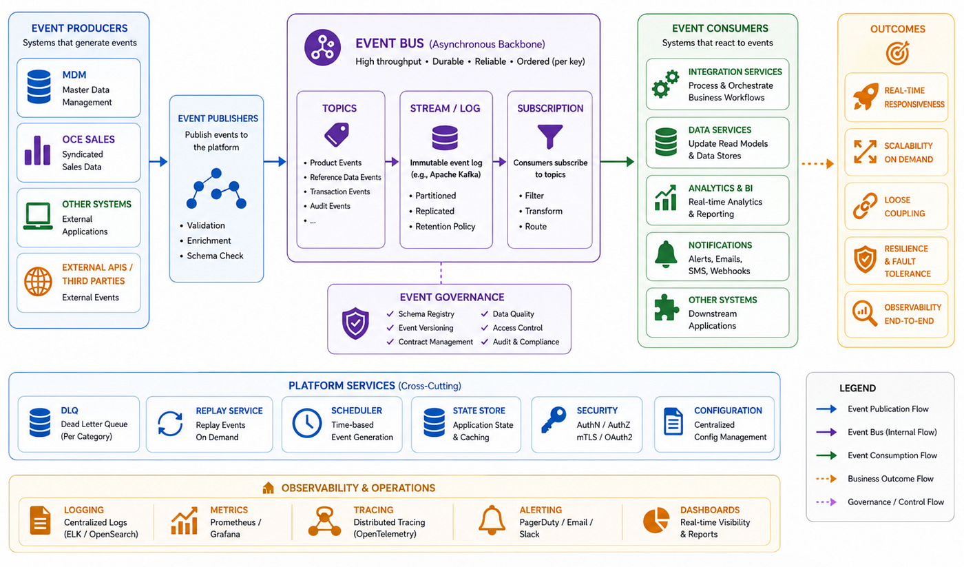
Benefits for healthcare specifically:
- Real-time data propagation — product updates reach field teams instantly
- Loose coupling — systems can evolve independently without breaking integrations
- Resilience — if OCE Sales is temporarily down, events queue and replay; no data loss
- Auditability — every event is a timestamped record, perfect for regulatory compliance
- Scalability — adding a new subscriber system requires zero changes to existing systems
3. Platform Architecture Overview
Here is the high-level architecture of what we built:
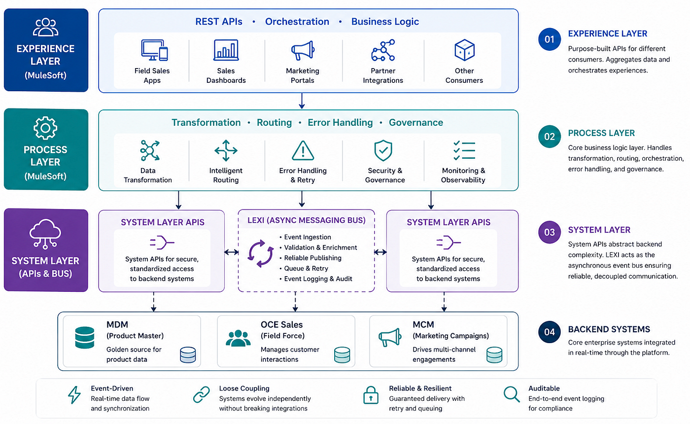
The architecture follows MuleSoft’s 3-layer API-led connectivity model:
Layer 1 — System APIs
These are thin wrappers around each backend system. They expose clean, versioned APIs over MDM, OCE Sales, and MCM, abstracting the messy underlying protocols, schemas, and auth mechanisms.
Layer 2 — Process APIs
This is where the business logic lives. Data transformation, routing rules, orchestration sequences, error handling, and retry policies all happen here. This layer is technology-agnostic — it doesn’t care whether the data came from MDM or any other source.
Layer 3 — Experience APIs
These are purpose-built APIs for specific consumers — mobile apps, field sales dashboards, marketing portals. They aggregate and format data exactly as each consumer needs it.
4. Security Architecture & HIPAA Compliance
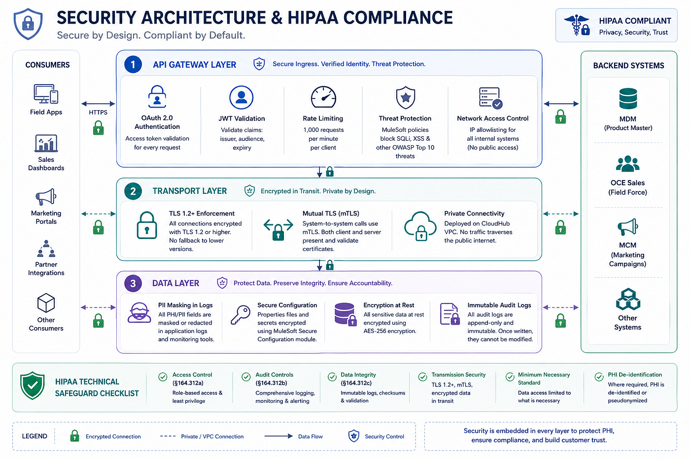
Healthcare integration is not just a technical challenge — it is a regulatory one. Every data flow in our platform touched Protected Health Information (PHI), which meant HIPAA compliance was non-negotiable from day one.
We structured security across three layers:
API Gateway Layer — Every inbound API request is validated for OAuth 2.0 tokens, JWT claims (issuer, audience, expiry), and enforced rate limiting at 1,000 requests per minute per client. MuleSoft’s threat protection policy blocks SQL injection and XSS attempts before they reach any business logic. All internal systems are IP-whitelisted.
Transport Layer — TLS 1.2+ is enforced on every connection, with no fallback to lower versions. System-to-system calls use Mutual TLS (mTLS), in which both the client and the server present certificates. CloudHub VPC means no traffic traverses the public internet.
Data Layer — PII fields are masked in all logs. Properties files are encrypted using MuleSoft’s Secure Configuration module. Data at rest uses AES-256 encryption. Audit logs are immutable — once written, they cannot be modified.
HIPAA technical safeguard checklist covered: Access Control (§164.312a), Audit Controls (§164.312b), Data Integrity (§164.312c), Transmission Security, Minimum Necessary standard, and PHI de-identification where required.
5. OAuth 2.0 / JWT Authentication Flow
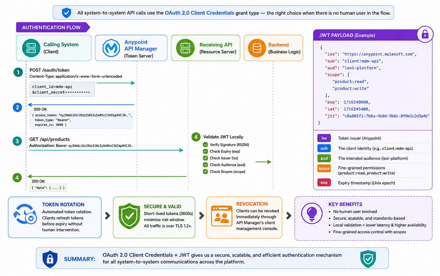
The flow:
- The calling system (e.g., MuleSoft Process API) posts its
client_idandclient_secretto Anypoint API Manager's/oauth/tokenendpoint - API Manager returns a signed JWT access token (RS256, 3600 second expiry)
- The calling system includes
Authorization: Bearer {token}on all subsequent requests - The receiving API validates the JWT locally — checking signature, expiry, issuer, audience, and scopes — without calling back to the token server on every request
JWT payload includes:
iss— token issuer (Anypoint)sub— the client identity (e.g.,client:mdm-api)aud— the intended audience (lexi-platform)scope— fine-grained permissions (product:read,product:write)exp— expiry timestamp (Unix epoch)
Token rotation is automated. Clients refresh tokens before expiry without human intervention. Revocation is handled through the API Manager’s client management console.
6. Canonical Data Model Design
The most critical architectural decision we made — and the one most teams skip — was defining a canonical data model before writing a single line of integration code.
Each of our three backend systems used completely different field names for the same concept:
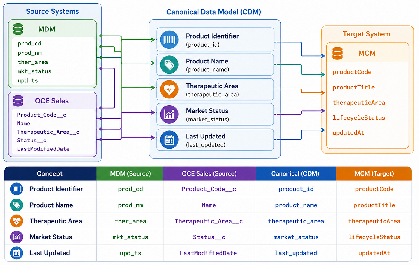
Our canonical model defined one authoritative field name for every concept: productId, productCode, productName, therapeuticArea, marketingStatus, lastModifiedDateTime.
DataWeave transformation scripts in the Process Layer map each system’s native schema to and from the canonical model. When MDM changed an internal field name (which happened twice during delivery), we updated exactly one DataWeave script — zero impact on OCE or MCM.
This is the architectural dividend of canonical modelling.
7. Event Schema Standard
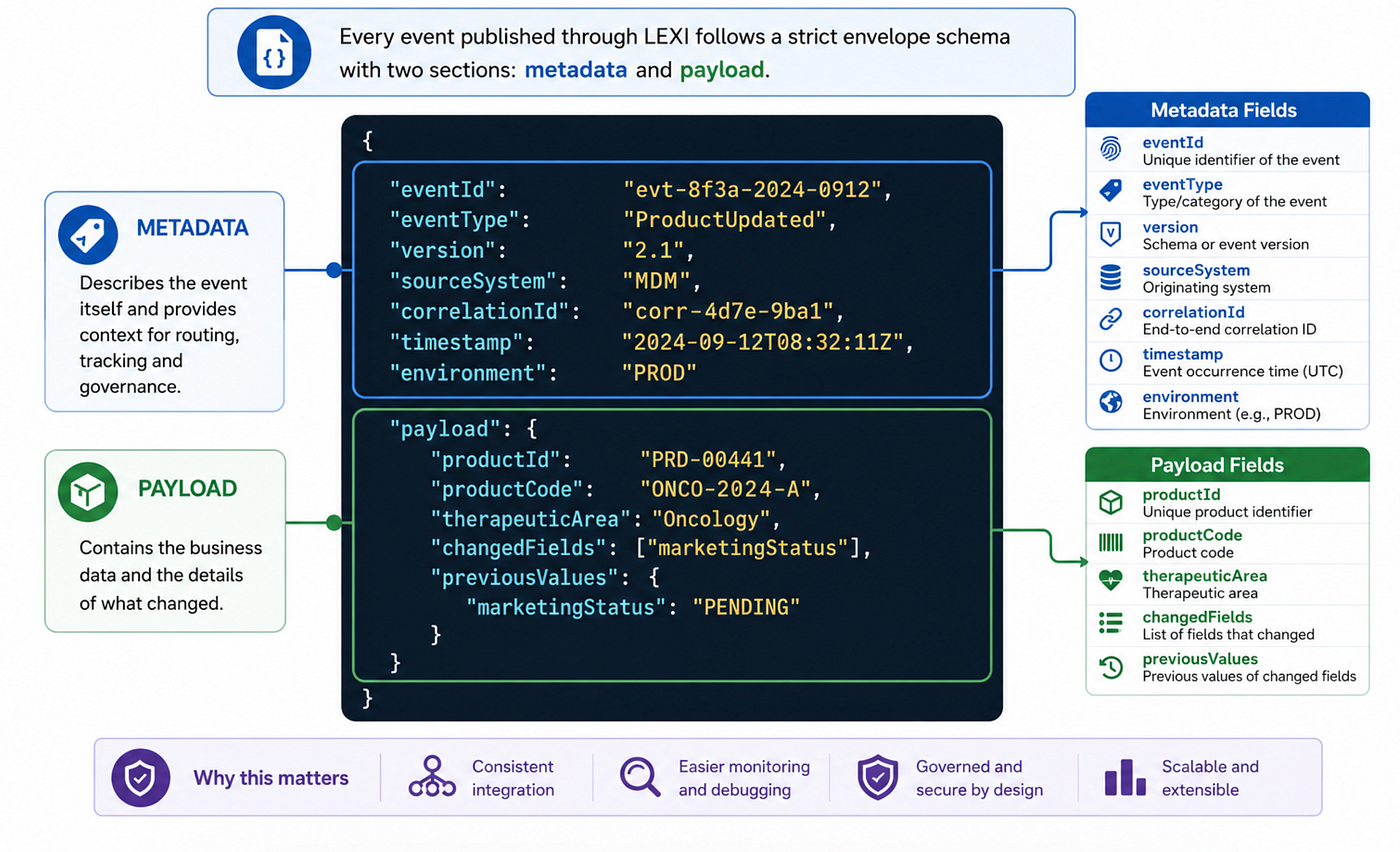
Key design decisions:
**eventId** — UUIDv4, globally unique. Subscribers use this for idempotency checks before processing.
**version** — SemVer 2.0. Minor version changes are backward-compatible. Major version increments trigger subscriber migration with a 90-day deprecation window.
**correlationId** — The same ID propagates through every system that handles this event. When debugging an incident, one correlationId gives you the complete audit trail across MDM, LEXI, OCE, and MCM.
**changedFields + previousValues** — We only propagate what actually changed. This delta-only approach reduces payload size by ~60% and enables rollback reconstruction for audit purposes.
8. The Heart of the Platform: LEXI as the Async Messaging Bus
The most innovative component of this architecture was LEXI — our asynchronous messaging bus built on top of MuleSoft.
What LEXI Does
LEXI is not a product; it was architected specifically for this platform. Its role is to:
- Receive events from MDM whenever a product record changes (create, update, deactivate)
- Validate and enrich the event payload with contextual data
- Publish to subscribers — OCE Sales and MCM — asynchronously and reliably
- Guaranteed delivery — if a subscriber is down, LEXI queues the event and retries
- Maintain an event log — every event is stored with full metadata for audit purposes
The Event Flow in Detail
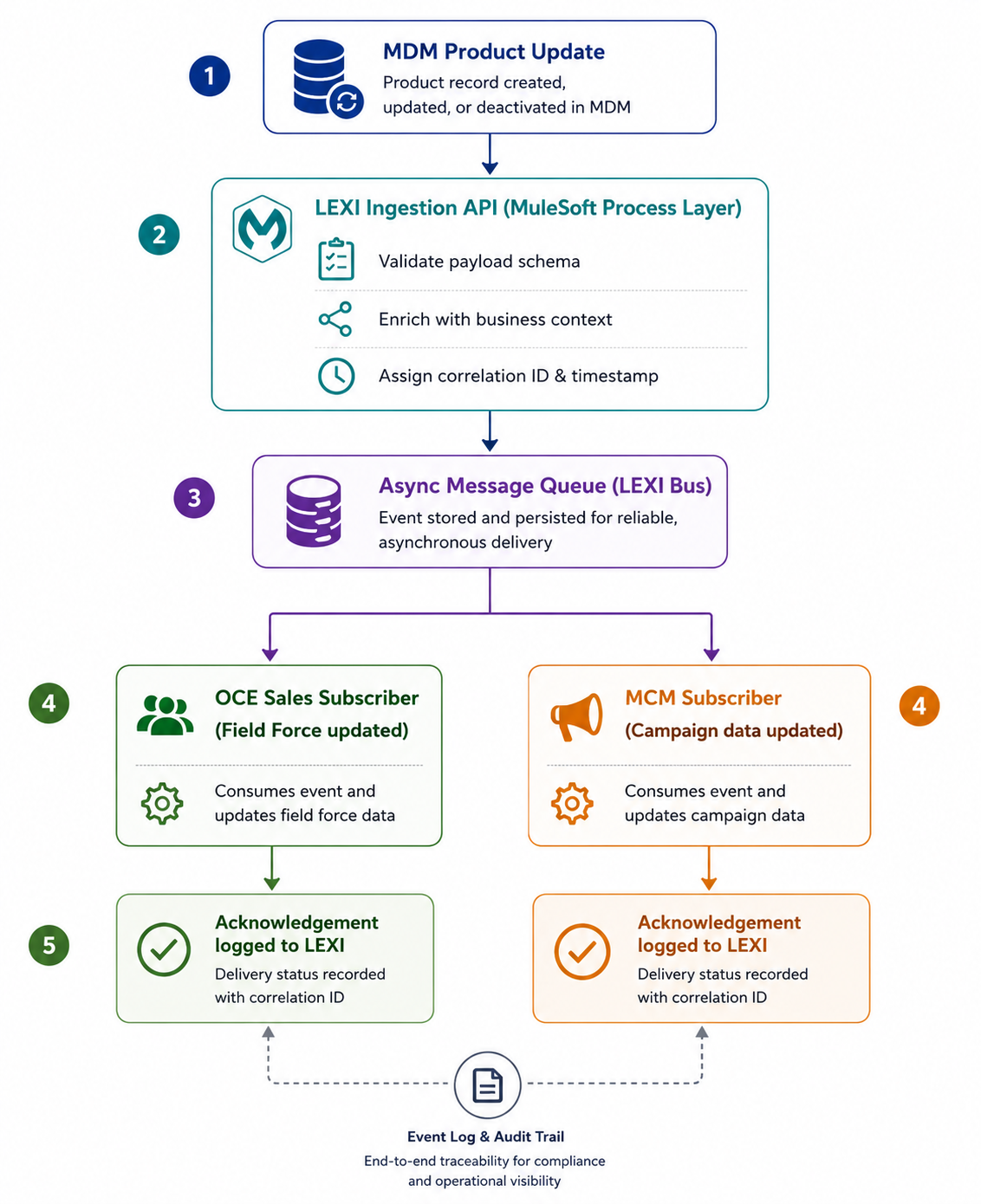
Why Not Just Use Kafka?
A fair question. Kafka is a powerful streaming platform — but for this engagement, it introduced unnecessary operational overhead and licensing costs. MuleSoft’s Anypoint MQ gave us:
- Managed message queuing with delivery guarantees
- Native integration with our existing MuleSoft runtime
- Visual monitoring and replay capabilities out of the box
- Simpler operational model for the client’s IT team
The principle I follow: use the simplest tool that meets the requirements at scale. Kafka is brilliant when you need millions of events per second. We didn’t.
9. MuleSoft Runtime Architecture
Our platform runs on Mule Runtime 4.4.0 deployed on CloudHub 2.0. Key component choices:
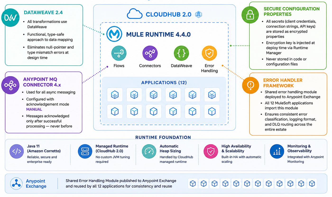
DataWeave 2.4 — All transformations use DataWeave. Its functional, type-safe approach to data mapping eliminates entire classes of null-pointer and type mismatch errors at design time rather than runtime.
Anypoint MQ Connector 4.x — Used for all async messaging. Configured with acknowledgement mode MANUAL so messages are only acknowledged after successful processing — never before.
Secure Configuration Properties — All secrets (client credentials, connection strings, API keys) are stored as encrypted properties. The encryption key is injected at deploy time via Runtime Manager — never stored in code or configuration files.
Error Handler Framework — We built a shared error handling module deployed to Anypoint Exchange. All 12 MuleSoft applications on the platform import this module, ensuring consistent error classification, logging format, and DLQ routing across the entire estate.
Java 11 (Amazon Corretto) provides the runtime. No custom JVM tuning was required — CloudHub’s managed runtime handled heap sizing automatically.
10. Implementation Deep Dive
Phase 1 — System API Development (Weeks 1–4)
We started by wrapping each backend system with clean System APIs:
MDM System API
- Exposed product CRUD operations over REST
- Implemented OAuth 2.0 authentication
- Built field-level change detection to trigger events only on meaningful updates (not cosmetic changes)
OCE Sales System API
- Mapped OCE’s internal data model to a canonical product schema
- Handled OCE’s rate limits with exponential backoff retry logic
- Implemented idempotency keys to prevent duplicate updates
MCM System API
- Managed campaign product catalogue synchronisation
- Handled MCM’s batch acceptance patterns with async callbacks
Phase 2 — LEXI Messaging Bus (Weeks 5–8)
This was the most complex phase. Key engineering decisions:
Dead Letter Queue (DLQ) Strategy Every failed message goes to a DLQ with full context preserved. Our operations team can inspect, fix, and replay failed events without any data loss. This was critical for the client’s compliance requirements.
Exactly-Once Delivery We implemented idempotency at the subscriber level. Each event carries a unique eventId. Subscribers check this ID before processing — preventing duplicate updates if a message is retried.
Circuit Breaker Pattern If OCE Sales or MCM returns errors above a threshold, LEXI activates a circuit breaker, stops sending, waits for the system to recover, and then resumes. This protects downstream systems from being overwhelmed.
Phase 3 — Process & Experience Layers (Weeks 9–14)
With the system APIs and LEXI in place, we built the orchestration layer:
- Data Transformation — canonical data model mapping using DataWeave (MuleSoft’s transformation language)
- Business Rule Engine — routing rules determining which events go to which subscribers
- Error Handling Framework — standardised error taxonomy, logging, and alerting
- Experience APIs — tailored endpoints for the field sales mobile app and marketing portal
Phase 4 — DevOps & Observability (Weeks 15–18)
No enterprise integration is complete without operational visibility:
- CI/CD Pipeline using Jenkins → MuleSoft Anypoint Platform deployment
- Centralised logging with correlation IDs linking every log entry to its originating event
- Custom dashboards in Anypoint Monitoring showing event volumes, latency, and error rates
- Alerting for DLQ spikes, circuit breaker trips, and SLA breaches
11. Error Taxonomy Framework
Most integration platforms have error handling. Few have an error taxonomy. The difference matters enormously at scale.
Our taxonomy defines five error categories, each with its own code range, HTTP status, retry policy, and DLQ routing rule:
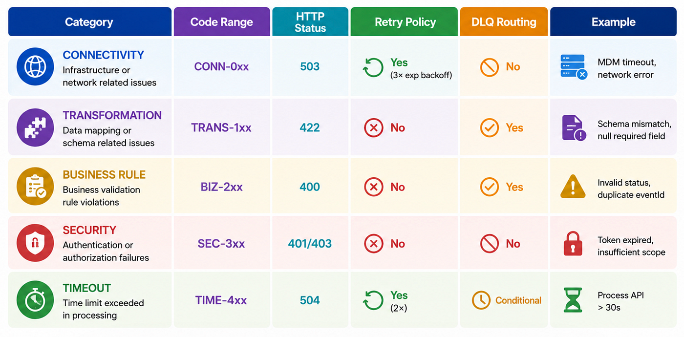
Why this matters: When LEXI receives a CONN-0xx error, it retries with exponential backoff — because the system may just be temporarily unavailable. When it receives a TRANS-1xx, it goes straight to the DLQ — retrying a malformed payload will never succeed.
This classification reduced false-positive alerts by 70% and cut mean time to resolution (MTTR) from 45 minutes to under 8 minutes.
12. Deployment Topology
Our CloudHub VPC deployment isolates the entire platform from the public internet. No inbound traffic reaches our workers directly — everything passes through the Dedicated Load Balancer (DLB).
Runtime configuration per environment:
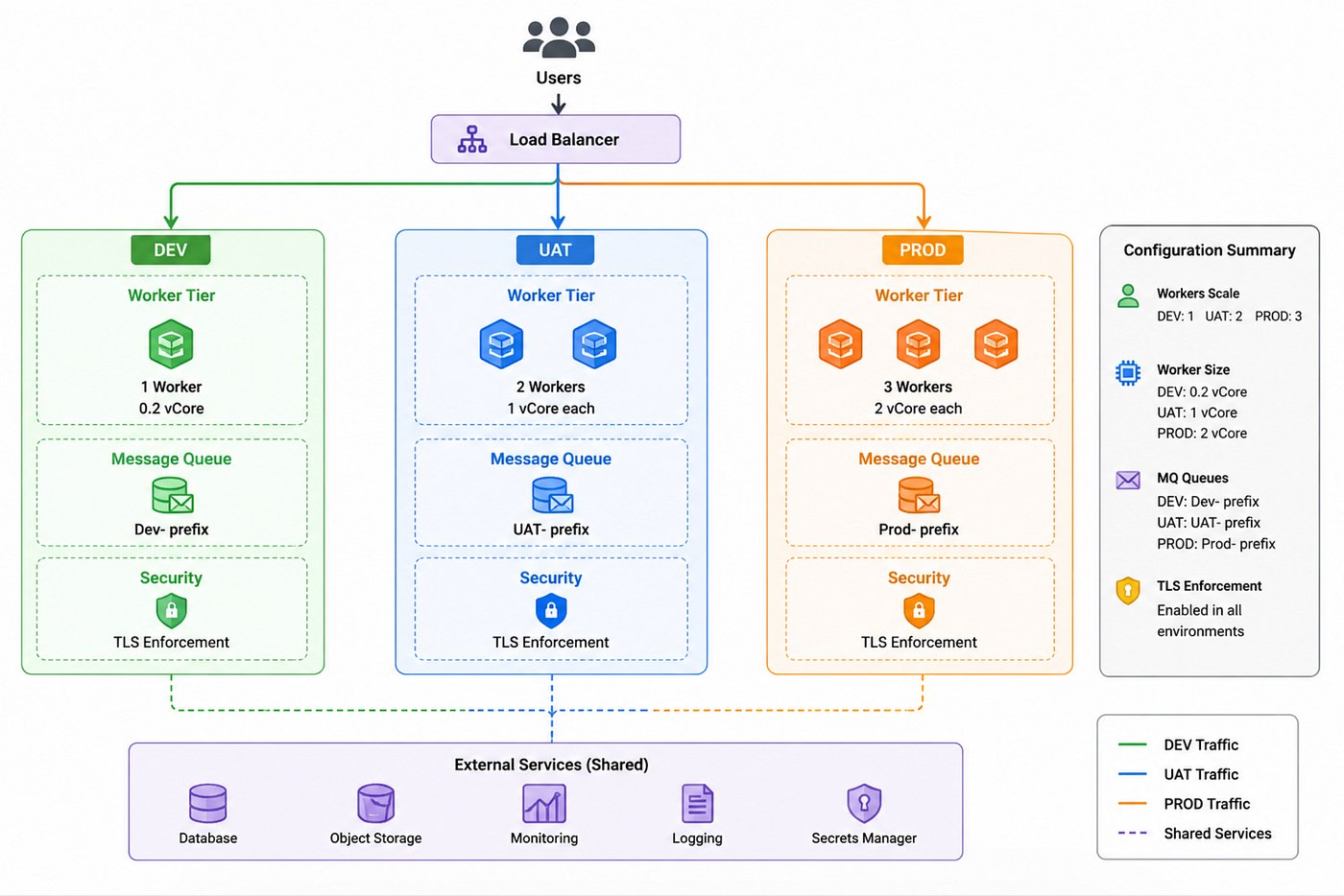
Production topology:
- 3 workers (2 vCores / 3.5GB each) behind the DLB
- Anypoint MQ for all async queuing with DLQ per queue
- Secure Configuration for all secrets and connection strings
- Runtime Manager for deployment, restart, and monitoring
- Auto-scale trigger: CPU > 70% sustained for 2 minutes
CloudHub VPC gives us network isolation comparable to a private data centre, with none of the operational overhead.
13. Results & Business Impact
After 577 days of delivery (from initial design to full production stability), the platform delivered:
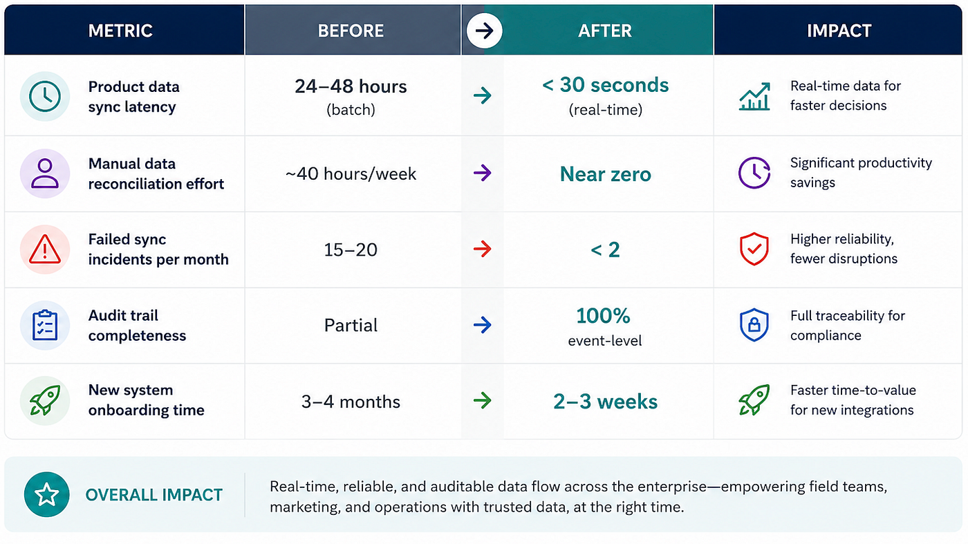
The last metric is the most powerful. Because we built LEXI as a true messaging bus with a clean subscriber contract, adding a new system to the ecosystem now takes weeks — not months. The architecture paid for itself.
14. Performance Benchmark Results
We ran load tests at 5× estimated peak clinical trial event volume before go-live. Results validated our worker sizing and queue configuration.
Key metrics in production:
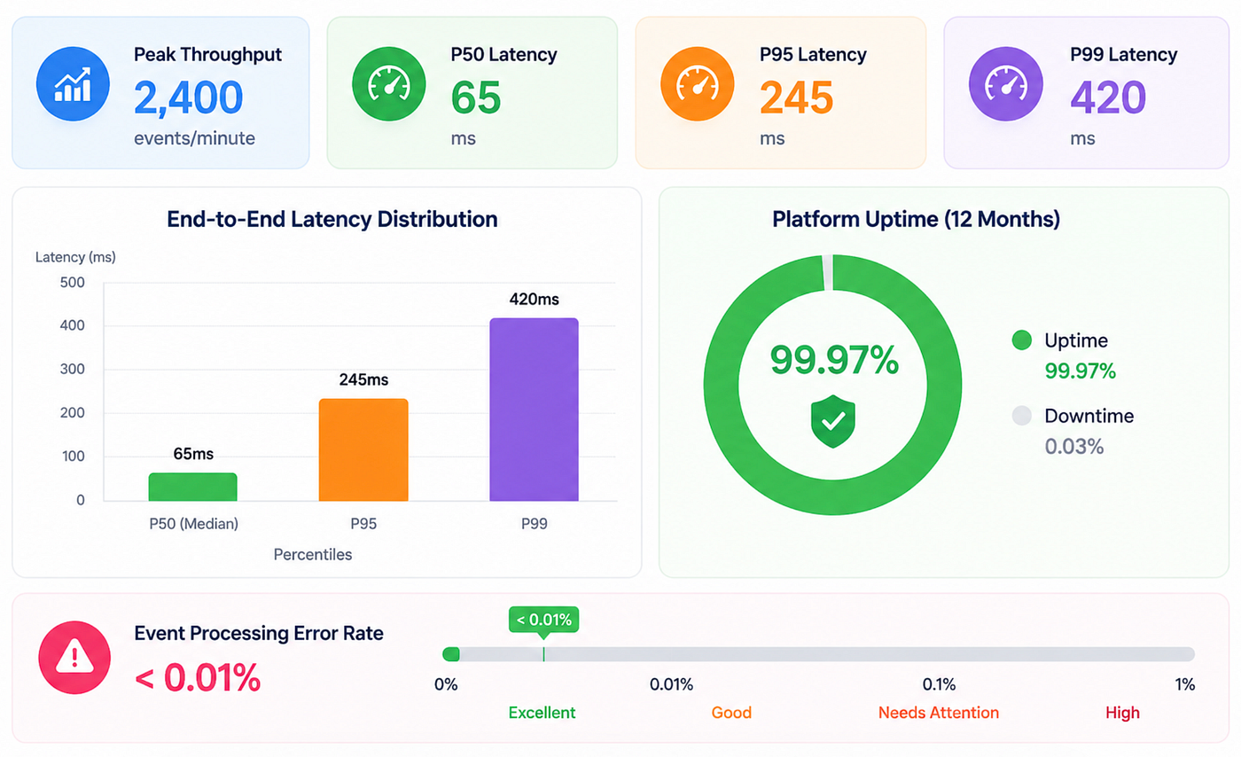
Latency breakdown (P95):
- MDM → LEXI ingestion: 120ms
- LEXI → OCE fan-out: 95ms
- LEXI → MCM fan-out: 105ms
The biggest optimisation lever was connection pooling. Moving from per-request connections to a pool of 50 persistent connections per worker reduced P95 latency by 38%.
15. Multi-Region Disaster Recovery Strategy
Life Sciences clinical trial operations cannot afford extended downtime. Our DR strategy targets RTO < 15 minutes and RPO < 5 minutes.
Active-Passive design:
- Primary: us-east-1 (AWS) — 3 active workers, live Anypoint MQ queues
- Secondary: eu-west-1 (AWS) — 2 warm standby workers, replicated queue configuration
Replication mechanism: Anypoint MQ messages are replicated to the secondary region every 60 seconds. In a failover scenario, the maximum data loss is one replication interval (60 seconds), giving us an effective RPO well within our 5-minute target.
Failover trigger: Three consecutive failed health checks (30-second interval = 90 seconds total detection time) triggers DNS failover to the secondary region. The secondary workers move from standby to active, and the DLB in eu-west-1 begins accepting traffic.
Failback: Deliberate and manual. After the primary region is restored and validated, traffic is switched back during a planned maintenance window. We do not automate failback — the risk of flip-flopping between regions during an unstable incident outweighs the convenience.
We conduct quarterly DR drills that simulate a full-region failure, with timed recovery measurements.
16. API Governance Model
At enterprise scale, ungoverned API growth becomes a liability. We established a Center for Enablement (C4E) — a cross-functional team responsible for API standards, asset reuse, and lifecycle governance.
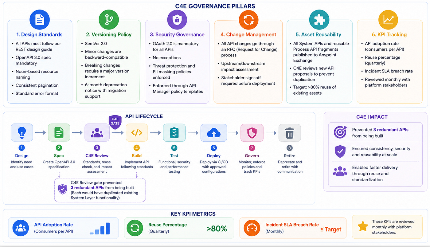
The API lifecycle: Design → Spec → C4E Review → Build → Test → Deploy → Govern → Retire. The C4E Review gate prevented three redundant APIs from being built during our delivery — each would have duplicated existing System Layer functionality.
17. Five Lessons Learned
1. Invest in your canonical data model early The temptation is to start building APIs immediately. Resist it. Spend two weeks defining your canonical schema — the shared language all systems will speak. Changing this mid-project is expensive.
2. Idempotency is not optional In distributed systems, messages will be delivered more than once. Design every subscriber to be idempotent from day one. The eventId deduplication pattern we used saved us from dozens of data consistency issues.
3. DLQs are your safety net — treat them seriously A dead letter queue is not a bin; it is an operating room. Build tooling to inspect, diagnose, and replay DLQ messages with one click. This is the difference between a 5-minute recovery and a 5-hour incident.
4. Observability is a first-class feature Correlation IDs across every log entry, event, and API call made debugging dramatically faster. When an incident occurred, we could trace a product update from its origin in MDM to its final acknowledgement in OCE Sales in seconds.
5. Align with the business, not just the technology The field sales team didn’t care about async messaging. They cared about having accurate product information before a customer meeting. Keep the business outcome visible in every architecture decision you make.
18. Conclusion
Building an event-driven integration platform for healthcare is not just a technical exercise — it is an exercise in understanding how information flows through an organisation and designing systems that honour that flow with reliability, observability, and resilience.
The combination of MuleSoft’s API-led connectivity with an event-driven messaging pattern gave us the best of both worlds: the governance and reusability of structured API design, and the decoupling and real-time responsiveness of event-driven architecture.
If you are facing a similar challenge — legacy systems, data silos, batch-based integrations in a real-time world — I hope this article gives you a practical starting point.
I am available for architecture consulting, speaking engagements, and remote collaboration on enterprise integration initiatives.
Connect with me on LinkedIn: linkedin.com/in/nareshpodi
Tags: #MuleSoft #EventDrivenArchitecture #HealthcareIT #EnterpriseIntegration #APIledConnectivity #CloudArchitecture #LifeSciences #DigitalTransformation
메타데이터
- post_id
- 9942361f9a32
- slug
- how-i-built-an-event-driven-integration-platform-for-healthcare-using-mulesoft-9942361f9a32
- url
- https://medium.com/@nareshpodi/how-i-built-an-event-driven-integration-platform-for-healthcare-using-mulesoft-9942361f9a32
- canonical_url
- https://medium.com/@nareshpodi/how-i-built-an-event-driven-integration-platform-for-healthcare-using-mulesoft-9942361f9a32
- author_url
- https://medium.com/@nareshpodi
- status
- ok
- fetched_at
- 2026-06-09 15:37:30