Multi-NIC Kubernetes Cluster — Demystifying Flannel Networking
In my previous article, I detailed the steps to set up a Multi-NIC Kubernetes cluster on bare metal, demonstrating how to segment cluster…
Multi-NIC Kubernetes Cluster — Demystifying Flannel Networking
In my previous article, I detailed the steps to set up a Multi-NIC Kubernetes cluster on bare metal, demonstrating how to segment cluster traffic :
- ens160 : OOB (Management / SSH / bootstrap) — (all nodes)
- ens192 : External (Internet / EXTERNAL-IP / remote client access) — (all nodes)
- ens224 : API Internal (Control Plane / etcd / kubelet ↔ API server ) — (all nodes)
- ens256 : UNDERLAY (Inter-node traffic carrying encapsulated pod-to-pod packets) — (worker only)
In this follow-up, I will explain the Kubernetes networking model and demystify how Flannel operates within this setup.
The Kubernetes Networking Model
Kubernetes networking is a foundational component, just as critical as pod scheduling or lifecycle management. Its purpose is to make pods behave like VMs or physical hosts, especially regarding :
- IP and port allocation
- Service discovery and DNS
- Load balancing and routing
- Application configuration
- Mobility (pods rescheduling across nodes)
But because pods run dynamically across multiple nodes, Kubernetes must ensure:
- No two pods conflict on IP addresses
- Connections work regardless of which node the pod lands on
To support this, Kubernetes adopts a simple fundamental rule:
Every pod receives a unique IP address routable across the entire cluster.
This rule drives Kubernetes networking to solve four core problems [1]:
- Container-to-container communication inside the same pod
- Pod-to-pod communication across nodes
- Pod-to-service communication via stable virtual IPs
- External-to-internal communication from outside the cluster
Kubernetes Networking Layers
Kubernetes networking consists of multiple layers. Only some parts are implemented directly by Kubernetes. The rest is delegated to the CNI (Container Network Interface), a CNCF project that defines how network plugins should configure network interfaces in Linux and Windows containers [2].
CNI provides:
- a specification
- a set of core plugins (bridge, host-device, vlan…) much like Docker network drivers
- a framework that third-party plugins extend
Third-party CNI plugins such as Flannel, Calico, Cilium implement full cluster networking solutions including:
- pod IP addressing (IPAM)
- routing, encapsulation, or BGP
- network policy enforcement
- service proxying (in some implementations)
Below is how Kubernetes networking fits together:
1. Container-to-Container Communication (within a Pod)
- Each pod has its own network namespace.
- All containers inside the pod share the same namespace → they communicate over localhost.
- The container runtime (e.g., containerd) creates and configures this namespace.
This is the simplest part — no CNI plugin is involved yet.
2. Pod-to-Pod Communication
Here, the CNI plugin takes over. It:
- Assigns a unique IP address (IPAM) to each pod
- Programs network connectivity so that all pods can reach all others, whether local or across nodes
3. Pod-to-Service Communication
Kubernetes Services expose consistent virtual IPs:
- The kube-apiserver allocates Service ClusterIPs.
- kube-proxy programs routing/iptables/IPVS to send traffic to healthy backend pods.
Some CNIs (Calico eBPF, Cilium) can replace kube-proxy entirely.
Services provide:
- Stable virtual endpoints (long-lived IP addresses)
- Load balancing
- Health-aware traffic routing
Regardless of where pods move, Services remain stable.
4. External-to-Internal Communication
To expose cluster Services to outside clients, Kubernetes provides:
- Gateway API (recommended modern API)
- Ingress API (widely used, older generation)
External load balancers or ingress controllers use these APIs to provide:
- HTTP/S routing
- L4/L7 load balancing
- TLS termination
- Policy enforcement
Demystifying Flannel — End-to-End Logic of Pod Networking
When bootstrapping the Kubernetes control plane with kubeadm, using a ClusterConfiguration manifest, the podSubnet was specified as follows:
apiVersion: kubeadm.k8s.io/v1beta4
kind: ClusterConfiguration
kubernetesVersion: v1.34.0
networking:
  podSubnet: "10.244.0.0/16"
  serviceSubnet: "10.96.0.0/12"
This configuration instructs the kube-controller-manager to automatically assign PodCIDRs by splitting the /16 subnet into /24 networks for each node.
Even when node-cidr-mask-size is not explicitly specified, the kube-controller-manager defaults to /24.
PodCIDR assignment per node
In our setup, PodCIDRs are visible as follows:
admink8s@master-01:~$ kubectl describe node master-01 | grep -i 'podcidr'
PodCIDR:   10.244.0.0/24
admink8s@master-01:~$ kubectl describe node worker-01 | grep -i 'podcidr'
PodCIDR:   10.244.1.0/24
admink8s@master-01:~$ kubectl describe node worker-02 | grep -i 'podcidr'
PodCIDR:   10.244.2.0/24
Notes:
- Even control-plane nodes (which may not schedule pods) receive PodCIDRs if
--allocate-node-cidrs=true. - If
--allocate-node-cidrs=false, the CNI plugin becomes responsible for assigning node subnets instead of the controller-manager. Flannel, however, expects Kubernetes to assign the PodCIDR.
How Flannel Uses the PodCIDR
The kubelet receives the PodCIDR from kube-controller-manager and passes it to the CNI plugin.
Flannel consists of two components:
| Component                                   | Purpose                                                                         |
| ------------------------------------------- | ------------------------------------------------------------------------------- |
| `flanneld` (DaemonSet)                      | Backend logic, VXLAN setup, subnet allocation, writes `/run/flannel/subnet.env` |
| Flannel CNI plugin (`/opt/cni/bin/flannel`) | Creates `cni0`, assigns IPs, manages veth pairs                                 |
flanneld (daemon) responsibilities:
- Receives PodCIDR and network configuration
- Allocates subnet lease
- Creates backend interface (
flannel.1for VXLAN) - Writes node subnet info to
/run/flannel/subnet.env
When kubelet starts a pod, it calls the CNI plugin defined in:
/etc/cni/net.d/10-flannel.conflistThe Flannel CNI binary then:
- Reads
/run/flannel/subnet.env - Creates
cni0bridge (if missing) - Assigns bridge IP:
10.244.X.1/24 - Creates veth pairs for pods
- Performs IPAM
- Configures default route in the pod via
cni0
Diagram of Flannel Architecture
flanneld (daemon)
   -------------------------
   | reads PodCIDR         |
   | creates flannel.1     |
   | writes subnet.env ----|----------------------+
   -------------------------                       |
                                                  (CNI plugin reads it)
                                                     |
                                                     v
                                  /opt/cni/bin/flannel CNI plugin
                                  --------------------------------
                                  | creates bridge cni0          |
                                  | configures pod veth pairs    |
                                  | assigns IPs from PodCIDR     |
                                  --------------------------------
Flannel VXLAN Implementation
When Flannel uses the VXLAN backend, it creates a VXLAN device:
flannel.<vni>By default:
- VNI = 1
- The device is flannel.1
Example:
admink8s@worker-01:~$ ip -d link show flannel.1
7: flannel.1: <BROADCAST,MULTICAST,UP,LOWER_UP> mtu 1450 qdisc noqueue state UNKNOWN mode DEFAULT group default
    link/ether 72:f3:b8:14:07:6e brd ff:ff:ff:ff:ff:ff promiscuity 0 minmtu 68 maxmtu 65535
    vxlan id 1 local 10.10.10.51 dev ens256 srcport 0 0 dstport 8472 nolearning ttl auto ageing 300 udpcsum noudp6zerocsumtx noudp6zerocsumrx addrgenmode eui64 numtxqueues 1 numrxqueues 1 gso_max_size 65536 gso_max_segs 65535
Output includes:
vxlan id 1- Underlay device (e.g.,
ens256) - UDP port
8472 nolearningflag → no multicast, no dynamic MAC learning
Why Flannel VXLAN Does Not Need BUM Traffic
Flannel’s VXLAN implementation is not EVPN (RFC 7432), popular in traditional DC spine-leaf VXLAN. Instead, Flannel uses a deterministic control plane. For each remote node, flanneld:
- Creates a route to the remote PodCIDR
- Creates a static ARP entry for the remote VTEP
- Creates a static FDB entry for the remote VTEP MAC
Flannel VXLAN is simplified:
- No flood-and-learn
- No BUM traffic handeling
- No EVPN control plane
Scaling is linear:
1 route + 1 ARP entry + 1 FDB entry per remote node
This makes it very lightweight for small/medium clusters.
Packet routing from Pod#1 to Pod#3 across nodes
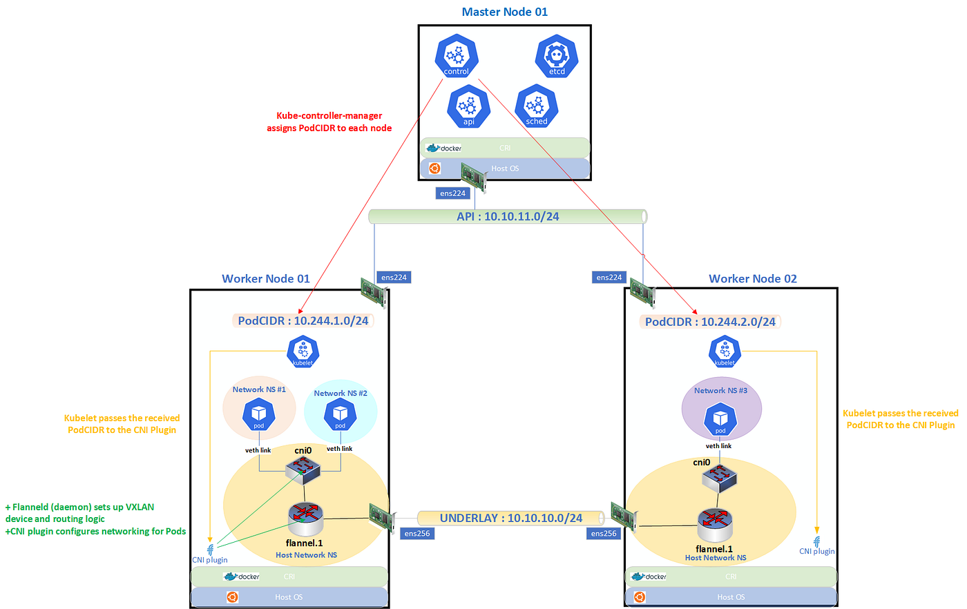
Let’s create two test pods using BusyBox:
kubectl run -it --rm pod1 --image=busybox --restart=Never -- sh
kubectl run -it --rm pod3 --image=busybox --restart=Never -- shpod1runs on worker-01pod3runs on worker-02
Check the pods and their assigned IPs:
admink8s@master-01:~$ kubectl get pods -n default -o wide
NAME   READY   STATUS    RESTARTS   AGE     IP            NODE        NOMINATED NODE   READINESS GATES
pod1   1/1     Running   0          2m5s    10.244.1.9    worker-01   <none>           <none>
pod3   1/1     Running   0          2m31s   10.244.2.10   worker-02   <none>           <none>
Now, imagine sending a ping from pod1 to pod3. First, let’s inspect the routing table inside pod1:
/ # ip route
default via 10.244.1.1 dev eth0
10.244.0.0/16 via 10.244.1.1 dev eth0
10.244.1.0/24 dev eth0 scope link  src 10.244.1.9
/ #
The eth0 interface details:
/ # ifconfig
eth0      Link encap:Ethernet  HWaddr BA:90:6F:AE:E2:EA
          inet addr:10.244.1.9  Bcast:10.244.1.255  Mask:255.255.255.0
          inet6 addr: fe80::b890:6fff:feae:e2ea/64 Scope:Link
          UP BROADCAST RUNNING MULTICAST  MTU:1450  Metric:1
          RX packets:35 errors:0 dropped:0 overruns:0 frame:0
          TX packets:36 errors:0 dropped:0 overruns:0 carrier:0
          collisions:0 txqueuelen:1000
          RX bytes:2682 (2.6 KiB)  TX bytes:2852 (2.7 KiB)
the default gatewy of Pod1 is the worker-1 cni0 bridge. The icmp echo packet leaving the Pod1 has :
IP src : 10.244.1.9 (Pod1)
IP dest : 10.244.2.10 (Pod3)
MAC src : ba:90:6f:ae:e2:ea (Pod1)
MAC dest : 8e:ad:7b:9b:39:49 (worker-1 cni0)
admink8s@worker-01:~$ sudo tcpdump -veni cni0 icmp
tcpdump: listening on cni0, link-type EN10MB (Ethernet), snapshot length 262144 bytes
22:41:12.372414 ba:90:6f:ae:e2:ea > 8e:ad:7b:9b:39:49, ethertype IPv4 (0x0800), length 98: (tos 0x0, ttl 64, id 27127, offset 0, flags [DF], proto ICMP (1), length 84)
10.244.1.9 > 10.244.2.10: ICMP echo request, id 15, seq 0, length 64Once the packet reaches cni0, worker-01 consults its routing table:
admink8s@worker-01:~$ ip route
default via 172.16.103.254 dev ens192 proto static
10.10.10.0/24 dev ens256 proto kernel scope link src 10.10.10.51
10.10.11.0/24 dev ens224 proto kernel scope link src 10.10.11.51
10.244.1.0/24 dev cni0 proto kernel scope link src 10.244.1.1
10.244.2.0/24 via 10.244.2.0 dev flannel.1 onlink
172.16.101.0/24 dev ens160 proto kernel scope link src 172.16.101.51
172.16.103.0/24 dev ens192 proto kernel scope link src 172.16.103.51
172.17.0.0/16 dev docker0 proto kernel scope link src 172.17.0.1 linkdown
192.168.250.0/24 via 172.16.101.254 dev ens160 proto static
admink8s@worker-01:~$
The network 10.255.2.0/24 is reachable via 10.244.2.0 (remote VTEP). Thus, the icmp echo packet is routed to the VXLAN device for encapuslation.
Packet fields on flannel.1 (before VXLAN encap):
IP src : 10.244.1.9 (Pod1)
IP dest : 10.244.2.10 (Pod3)
MAC src : 72:f3:b8:14:07:6e (worker-1' flannel.1)
MAC dest : 82:e3:e8:2a:65:f6 (remote VTEP)
admink8s@worker-01:~$ sudo tcpdump -veni flannel.1 icmp
tcpdump: listening on flannel.1, link-type EN10MB (Ethernet), snapshot length 262144 bytes
22:40:05.975664 72:f3:b8:14:07:6e > 82:e3:e8:2a:65:f6, ethertype IPv4 (0x0800), length 98: (tos 0x0, ttl 63, id 12057, offset 0, flags [DF], proto ICMP (1), length 84)
10.244.1.9 > 10.244.2.10: ICMP echo request, id 14, seq 0, length 64The mac of remote VTEP is already knwon and populated by Flanneld:
admink8s@worker-01:~$ ip neigh show dev flannel.1
10.244.2.0 lladdr 82:e3:e8:2a:65:f6 PERMANENT
Finally, the underlay interface ens256 sends the VXLAN UDP packet to the remote VTEP.

I hope this article helps you understand the K8S networking model and gives you a clear understanding of Flannel.
메타데이터
- post_id
- a23f2a716a1b
- slug
- multi-nic-kubernetes-cluster-demystifying-flannel-networking-a23f2a716a1b
- url
- https://medium.com/@mohamed.mazhoud/multi-nic-kubernetes-cluster-demystifying-flannel-networking-a23f2a716a1b
- canonical_url
- https://medium.com/@mohamed.mazhoud/multi-nic-kubernetes-cluster-demystifying-flannel-networking-a23f2a716a1b
- author_url
- https://medium.com/@mohamed.mazhoud
- status
- ok
- fetched_at
- 2026-06-27 08:54:08