How to use the 1.9-inch TFT display of your Heltec Vision Master T190 ESP32-S3 board
The Heltec Vision Master T190 development board comes with an ESP32-S3 microcontroller, 16 MB Flash, and 8 MB PSRAM memory. There is an…
How to use the 1.9-inch TFT display of your Heltec Vision Master T190 ESP32-S3 board
The **Heltec Vision Master T190 development board comes with an ESP32-S3 microcontroller, 16 MB Flash, and 8 MB PSRAM memory. There is an HT-RA62 LoRa module (an SX1262 under the hood) and a 1.9-inch TFT display driven by an ST7789 chip **mounted on the board. The whole package is rounded off by two buttons and a white LED.
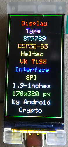
This all sounds like a powerful development board, but there are no official examples of the board, and many users complain about a display that cannot be controlled. This tutorial will show how to control the display with the **Adafruit ST77xx and the [TFT_eSPI](https://github.com/Bodmer/TFT_eSPI)** library by Bodmer.
The good news is Heltec is providing a **schematic** that has all internal GPIOs to run the display. Here is the ESP32-S3 processor and the pins in use:

Just look around and note all GPIO pins with “TFT”: starting at the top and moving clockwise, I found these pins for the SPI interface:
TFT RST 40
TFT CS  39
TFT SCL 38
TFT RS  47 (this is the DC pin)
TFT SDA 48 (this is the MOSI pin)
Now let's move to the right in the schematic, where the display circuit is shown:

Beneath the five SPI pins, there are two more connections that are of interest to us. At the top, an input “VTFT Ctrl” is connected to a MOSFET transistor that controls the complete 3.3 volts rail of the display. That means the display part of the board can get completely isolated to save power. The other input is “LEDK EN,” which controls an AW9364DNR chip. The output goes to the 4 LEDs that are the backlight source of the display. This pin is responsible for the dimming of the display.
Moving back to the microcontroller part, here are the GPIO pins:
VTFT Ctrl  7
LEDK EN   17
One small potential problem still awaits us. The display only receives power (“ON”) when the “VTFT Ctrl” is set to LOW.
Taking all the facts into account, we need this setup to use the Adafruit ST77xx library:
#include <Adafruit_GFX.h>     // Core graphics library
#include <Adafruit_ST7789.h>  // Hardware-specific library for ST7789
#include <SPI.h>

#define TFT_MISO -1
#define TFT_MOSI 48
#define TFT_SCLK 38
#define TFT_CS 39
#define TFT_DC 47
#define TFT_RST 40
#define TFT_BL 17

#define TFT_VCtrl 7

Adafruit_ST7789 tft = Adafruit_ST7789(TFT_CS, TFT_DC, TFT_RST);

in setup():
  // V TFT Control for the display
  pinMode(TFT_VCtrl, OUTPUT);
  digitalWrite(TFT_VCtrl, LOW);  // put the display on
  // TFT LED backlight brightness control
  pinMode(TFT_BL, OUTPUT);
  digitalWrite(TFT_BL, HIGH); // put the display on

  // Changing the Hardware SPI pins
  SPI.begin(TFT_SCLK, TFT_MISO, TFT_MOSI, TFT_CS);

  tft.init(170, 320);  // Init ST7789 320x170
When using the TFT_eSPI library, you need to copy the ‘Setup813_Heltec_VMT190_170_320.h’ file to the ‘User_Setups’ folder and change the ‘User_Setup_Select.h’ file accordingly.
Summary
Thanks to the available schematic drawing, it is easy to control and operate the 1.9-inch display of the Heltec Vision Master T190.
Source code of the apps
You find the complete code of the apps in my GitHub repository.
Happy coding !
메타데이터
- post_id
- a7a6176c0cda
- slug
- how-to-use-the-1-9-inch-tft-display-of-your-heltec-vision-master-t190-esp32-s3-board-a7a6176c0cda
- url
- https://medium.com/@androidcrypto/how-to-use-the-1-9-inch-tft-display-of-your-heltec-vision-master-t190-esp32-s3-board-a7a6176c0cda
- canonical_url
- https://medium.com/@androidcrypto/how-to-use-the-1-9-inch-tft-display-of-your-heltec-vision-master-t190-esp32-s3-board-a7a6176c0cda
- author_url
- https://medium.com/@androidcrypto
- status
- ok
- fetched_at
- 2026-06-13 12:55:53