The Awe-Inspiring Iterative Dance of QoS Design
Quality of Service (QoS) refers to tools that network devices can use to manage several related characteristics of what happens to a packet…
The Awe-Inspiring Iterative Dance of QoS Design
Quality of Service (QoS) refers to tools that network devices can use to manage several related characteristics of what happens to a packet while it flows through a network. QOS refers to the tools that networking devices use to apply some different treatment to packets in the network as they pass through the device; Specifically, these tools manage the bandwidth made available to that type of packet, the delay the packet experiences, the jitter (variation in delay) between successive packets in the same flow, and the percentage of packet loss for packets of each class. These tools balance the trade-offs of which types of traffic receive network resources and when, giving more preference to some traffic and less preference to others. QoS refers to tools that network devices can use to manage several related characteristics of what happens to a packet:
- Bandwidth made available to that type of packet.
- The Delay the packet experiences (LATENCY).
- The Jitter (Variation in delay) between successive packets in the same flow, and the percentage of packet loss for each. Specifically, these tools manage related characteristics of packet classes [types]. These tools balance the trade-off of which types of traffic receive network resources, and when, giving more preference to some traffic and less preference to others.
Per-Hop Behaviors QoS tools define actions a device can apply to a packet between the time it enters the device until it exits the device. Such actions can delay, discard, or even change header fields. QoS defines these actions as per-hop behaviors (PHBs), which is a formal term to refer to actions other than storing and forwarding a packet. These actions can delay the message, discard it, or even change header fields. The device can choose different PHBs for different kinds of messages, improving the QoS behavior for some messages, while worsening the QoS behavior for others. QoS tools change the QoS characteristics of certain flows in the network. Common for per-hop behaviors for QoS include classification, marking, queuing, policing, and shaping. Overall, QoS refers to the tools that devices apply to serve differential treatment to packets as they traverse the network.
QOS TOOLS give you the means to manage characteristics of Network Traffic: such as Bandwidth, Delay(Latency), Jitter and Loss.
- BANDWIDTH: Capacity usage of the link. Bandwidth refers to the speed of a link, in bits per second (bps). But while we think of bandwidth as speed, it helps to also think of bandwidth as the capacity of the link, in terms of how many bits can be sent over the link per second. The networking device’s QoS tools determine what packet is sent over the link next, so the networking device is in control of which messages get access to the bandwidth next and how much of that bandwidth (capacity) each type of traffic gets over time.
- DELAY (LATENCY): Time Taken for one-way / Round-trip. Delay can be described as one-way delay or round-trip delay. One-way delay refers to the time between sending one packet and that same packet arriving at the destination host. Round-trip delay counts the one-way delay plus the time for the receiver of the first packet to send back a packet — in other words, the time it takes to send one packet between two hosts and receive one back.
- JITTER: Variation in successive one-way Delay/Latency. Jitter refers to the variation in one-way delay between consecutive packets sent by the same application
- LOSS: Percentage of lost packets during transmission. Loss refers to the number of lost messages, usually as a percentage of packets sent. Loss can be caused by many factors, but often, people think of loss as something caused by faulty cabling or poor WAN services. That is one cause. However, more loss happens because of the normal operation of the networking devices, in which the devices’ queues get too full, so the device has nowhere to put new packets, and it discards the packet.
Several QoS tools manage queuing systems to help control and avoid loss. While QoS tools focus on managing bandwidth, delay, jitter, and loss, the user mainly cares about the quality of the overall experience, So, as a user, you care about the Quality of Experience (QoE), which is a term referring to users’ perception of their use of the application on the network. QoS tools directly impact bandwidth, delay, jitter, and loss, which then should have some overall good effect to influence the users’ QoE. And you can use QoS tools to create a better QoE for more important traffic.
Types of Traffic
- Interactive Data Applications: i.e Web Traffic
- Non-Interactive / Batch Applications: This includes data backup or file transfers, which have different QoS Requirements than Interactive Data Applications like Web traffic. Batch Applications send out more data than Interactive Applications but due to less interaction from the user, delay & jitter do not matter much, because it’s more important for these apps to complete the larger task (e.g., sending many files) within a longer time window. 3. Voice and Video Applications: Both Applications have similar breakdown of Interactive & Non-Interactive “Flows.” A Flow is all the data moving from one application to another over the network, with one flow for each direction. However, Interactive Voice QoS requires a much better level of quality regarding delay, jitter, and loss → less delay, little or less jitter, and better/ ideally no packet loss. Cisco’s Enterprise QoS Solution Reference Network Design Guide suggests the following guidelines for Interactive Voice Applications:
- Delay (one-way): 150 ms or less
- Jitter: 30 ms or less
- Loss: 1% or less Think of Video like Voice but with a much higher bandwidth requirements than Voice (per flow) & similar requirements for Delay, Jitter, and loss. As for Bandwidth, video can use a variety of codecs that impact the amount of data sent, but more technical features impact the amount of bandwidth required for a single video data flow are: Image Resolution (no. of pixels) + Color Depth (RGB) + Frame Rate (FPS). End-to-End QoS Network Design Guide for Video Applications:
- Bandwidth: 384 kbps → 20+ Mbps
- Delay (one-way): 200–400ms
- Jitter: 30–50ms
- Loss: 0.1% — 1%
Categories of QOS tool functionalities
Classification” refers to a type of QoS tool that classifies packets based on their header contents, and then marks the message by changing some bits in specific header fields. Thereby marking the packets and defining trust boundaries. Every QoS tool can examine various headers to make comparisons to classify packets. However, you might apply QoS tools on most every device in the network, sometimes at both ingress and egress on most of the interfaces. Using complex matching of many header fields in every device and on most interfaces requires lots of configuration. The work to match packets can even degrade device performance of some devices. So, while you could have every device use complex packet matching, doing so is a poor strategy. A better strategy, one recommended both by Cisco and by RFCs, suggests doing complex matching early in the life of a packet and then marking the packet. Marking means that the QoS tool changes one or more header fields, setting a value in the header. Several header fields have been designed for the purpose of marking the packets for QoS processing. Then, devices that process the packet later in its life can use much simpler classification logic. Classification: Organizes network traffic into traffic classes (categories). To give priority to certain types of traffic, you have to identify which types of traffic to give priority to. Methods of classification include: An Access Control List (ACL): Traffic which is permitted by the ACL will be given certain treatment. Network Based Application Recognition (NBAR): Performs a deep packet inspection looking beyond Layer 3/4 up to Layer 7 to identify the specific kind of traffic. In Layer 2/3 headers.
- PCP (Priority Code Point) field of the Ethernet — 802.1Q tag: Only when there’s a dot1Q tag, Class of Service (CoS) * DSCP (Differentiated Services Code Point) field of the IP Header: Can be used to prioritize traffic.
- TID header (exists in 802.11) over Wi-Fi
- EXP Header (MPLS label) over MPLS WAN
Marking: IP DSCP and Ethernet CoS QoS Tools are set in the path that packets take when being forwarded through a Router/Switch, much like the positioning of ACLs. QoS tools like ACLs, are enabled on an interface, in a specified direction:
- Packets entering the Interface (before the forwarding decision) [for any packet matched by an ACL, not a permit action, consider that packet a match for QoS, so apply a particular QoS Action].
- Packets exiting the Interface (after the forwarding decision). ACLs can have the purpose (action) of choosing which packet to discard by performing Classification (matching of header fields) to decide which packet to take certain QoS actions against.
The purpose of Marking: Using complex matching of many header fields in every device on one or more interfaces (Ingress -> Egress) requires lots of configurations. While it could have every device use complex packet matching, this is a poor strategy. A better strategy recommended by both Cisco & RFCs suggests doing complex matching only in the early life of a packet, and then marking the packet.
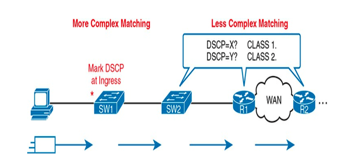
“Marking” means that the QoS Tool changes one or more header fields, setting a value in a header. Several header fields have been designed for the purpose of marking the packets for QoS processing. Then, devices that process the packet later in its life can use much simpler matching.
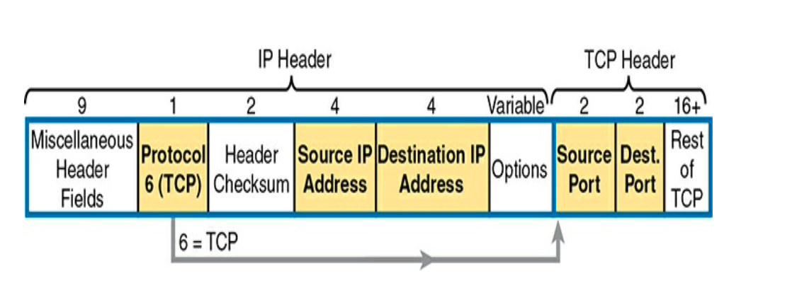
Marking a QoS field in the IP Header works well with QoS because the IP Header exists for the entire trip. Routers forward the IP packet, discarding the old data-link header and adding a new header. Because routers do not discard and reinsert IP headers, marking fields in the IP header stay with the data from the first place it is marked until it reaches its destination. ** IPv6 defines a TRAFFIC CLASS Byte.* ** IPv4 defines a Type of Service (ToS) byte in its header.*
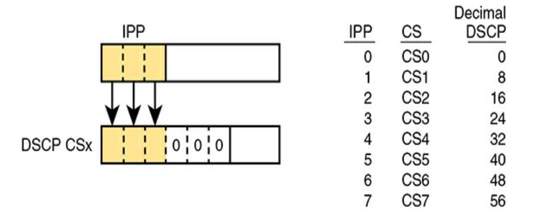
The original RFC defined a 3-bit IP Precedence (IPP) field for QoS marking.
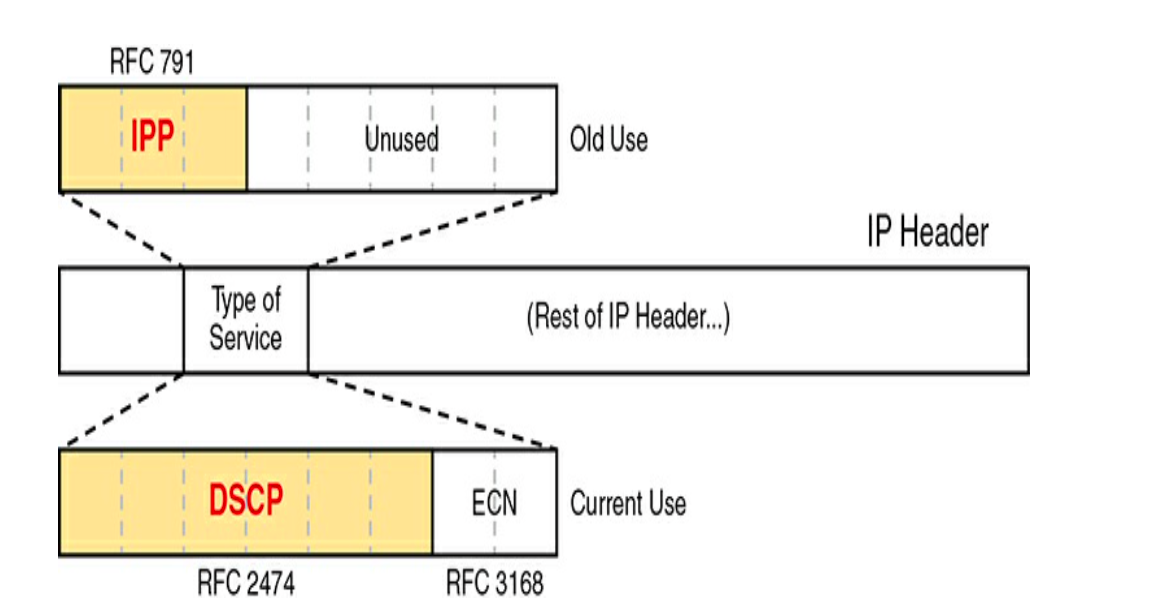
The remaining 5 bits of the ToS byte were unused. * Later RFCs redefined the (ToS) byte with the DSCP field, which increased the number of marking bits from 3 (8 possible values) -> 6 bits (2⁶ -> 64 possible values) that can be marked. IPP and DSCP fields can be referenced by their decimal values as well as some convenient names.
Marking the Ethernet 802.1Q Header in a field originally defined by the IEEE 802.1p standard. The field sits in the 3rd byte of the 4-byte 802.1Q header, as a 3-bit field (3 possible values). It goes by the names: Class of Service (CoS) / Priority Code Point (PCP).
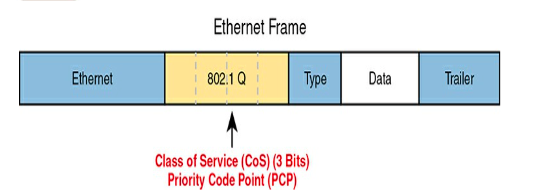
However, the 802.1Q header isn’t included in all Ethernet frames; it exists only when 802.1Q trunking is used on the link. As a result, QoS Tools can make use of the CoS field only for QoS features enabled on interfaces that are trunking.
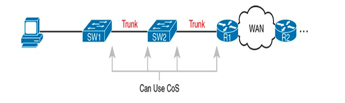
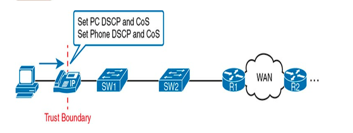
Trust boundary refers to the point in the path of a packet flowing through a network at which the Network Engineer creating a QoS plan has to choose where to place the trust boundary for a network.
If the markings are trusted, the device will forward the packet without changing the markings, else if they are untrusted, the device will change the markings according to the configured policy.

That boundary typically sits on a device under the control of the IT staff. IP phones can typically be a trust boundary, instead of an Access layer switch. IP phones can set the CoS and DSCP fields of the packets created by the phone, as well as those forwarded from the PC through the phone.
DiffServ Suggested Marking Values: By suggesting specific markings for specific types of traffic, DiffServ hoped to create a consistent usage of DSCP values in all networks. By doing so, product vendors could provide good default settings for their QoS features. * DiffServ — Default Forwarding (DF): DSCP 0* DiffServ — Expedited Forwarding (EF) RFC 3246: (Decimal 46)** for low latency, low jitter, low loss. This is for voice payload & other packets carrying call signaling packets (messages to setup/create the Voice Call between phones). Voice signaling do not require low delay, jitter, or loss, though the voice payload needs better QoS as they carry the actual digitized voice. By default, Cisco IP phones mark voice payload at EF and mark voice signaling packets sent by the phone with another value called CS3. * DiffServ — Assured Forwarding (AF) RFC 2597: Defines a set of 12 DSCP values (from 64 possible values) meant to be used in concert with each other. 1.) Four Separate Queues in a Queuing system. 2.) Three levels of Drop priority within each queue for use with Congestion Avoidance Algorithms.
- For 4 queues, 3 drop priority classes per queue, you need 12 different DSCP markings (one for each combination of queue and drop priority for queuing and congestion avoidance).

CLASS SELECTOR (CS): Recreates eight DSCP values (from 64 possible values) for Backward Compatibility with IPP Values (3-bit field with 8 possible values).
“Cisco QoS Design Guides” RFC 4954 defines several conventions for how to use the DSCP field. The RFC provides alternative plans with different levels of regard. Each plan defines a type of traffic and the DSCP value to use when marking. Cisco has developed RFC 4954 and uses its default marking conventions based on the marking data in RFC.
- DSCP EF: Voice payload (46)
- AF41 (AF42): Interactive Video (34, 36)
- AF31 (AF32): Streaming Video (non-Interactive) (26, 28)
- AF21 (AF22): High Priority (low latency) data (18, 20)
- CSO: Standard Data (0)
Queuing and Congestion Avoidance The term “Queuing” refers to the QoS tools for managing the queues that hold packets while they wait their turn to exit an interface. The queuing system may use a simple Output Queue with a FIFO Scheduler. Most Networking devices can have a queuing system with Multiple Queues. To use multiple Queues, the queuing system needs a classifier function to choose which packets are placed into which queue. The Queuing System needs a Scheduler as well, to decide which packet to take next when the interface becomes available. The scheduler performs Prioritization — the concept of giving priority to one queue.

Prioritization Techniques
- Round-Robin scheduling: Cycles through the queues in order, taking turns with each queue. Not Good for Voice & Video data traffic; Apply to Best-Effort / less critical traffic Queues.
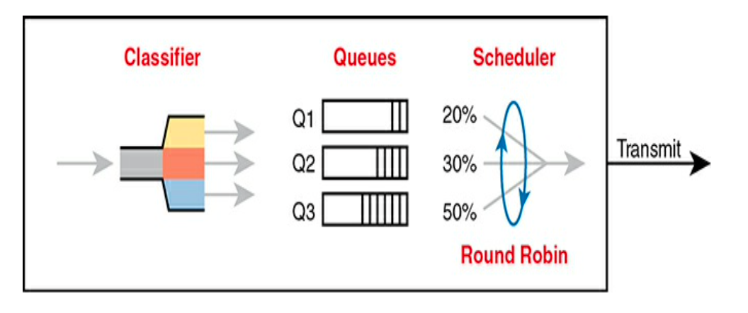
- Weighted Round-Robin: In each cycle, the Scheduler either takes one packet or takes a number of bytes from each queue by taking enough packet bytes to reach that number of bytes. Also included in the concept of “Weighting” — Scheduler takes a different number of packets (bytes) from each queue, giving more preference to one queue over another. Routers use a tool called Class-Based Weighted Fair Queuing (CBWFQ).
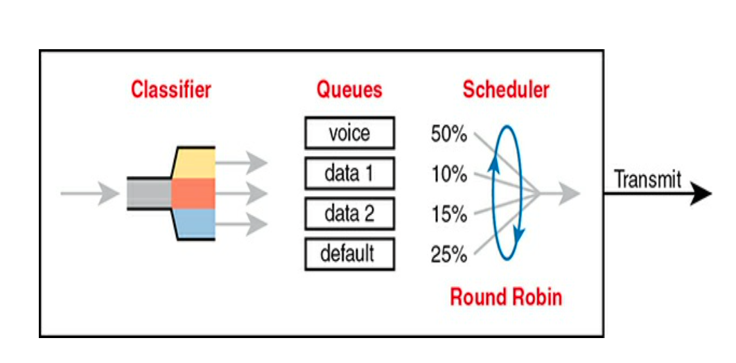
- CBWFQ (Class-Based Weighted Fair Queuing): Each class receives at least a guaranteed amount of bandwidth during times of congestion but maybe more. Internally, CBWFQ uses a Weighted R-R Scheduling algorithm, while letting the network admin define the weightings as a fixed link bandwidth percent.
Unfortunately, a Round Robin Scheduler doesn’t provide low enough delay, jitter, or loss for Video. The Solution: Add Low Latency Queuing (LLQ) to the Scheduler. A round-robin queuing system might add too much delay for Video/Voice packets because of the shuffling or cycling to pick packets from other queues. tells the scheduler to treat one or more queues as PRIORITY Queues. The LLQ Scheduler always takes the next packet or bytes during times of congestion from one of these special priority queues. As such, the queue (LLQ) might never have time to fill up, guaranteeing low delay, jitter, or loss to packets executing in LLQ / priority queues.
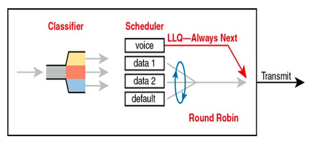
Unfortunately, Using LLQ might also lead to a problem of other “Queue Starvation.” The Solution: Traffic policers which limit the amount of traffic placed into a priority LLQ queue. Limiting the amount of bandwidth in the priority LLQ queue protects other queues, but this presents another problem of Loss. Voice & Video traffic require Low Loss and with policing the LLQ queue, we put the Voice/Video traffic into a priority Queue that will discard the excess messages beyond the Bandwidth Limit. The solution? Find a way to limit the amount of Voice & Video traffic that the network routes out through the link (Interface), so that the policer never discards any traffic.

Shaping and Policing (mostly at WAN Edge) “Shaping and Policing” explains these two tools together because they are often used on opposite ends of a link. All these tools give you the means to manage four characteristics of network traffic: Bandwidth — Delay — Jitter — Loss. Both policing and shaping monitor the bitrate of combined messages that flow through a device. Once enabled, a policer or shaper notes each packet that passes & measures the number of bits per second. Both attempt to keep the bitrate at or below the configured bandwidth, but by using different actions.
- Policers discard packets.
- Shapers hold packets in queues to delay the packets.
POLICERS allow for a burst beyond the policing rate for a short time, after a period of low traffic activity. Such peaks in network traffic are allowed for the nature of bursty data applications. In Summary: Policers measures the traffic rate over time for comparison to the configured policing rate. Policers allows for a burst of data after a period of inactivity. Policers are enabled on an interface, in either direction, but typically at ingress. Policers can discard excess messages but can also remark the message so that it’s a candidate for more aggressive discard later in its journey (i.e., re-classify packet into Higher Drop precedence for QoS).
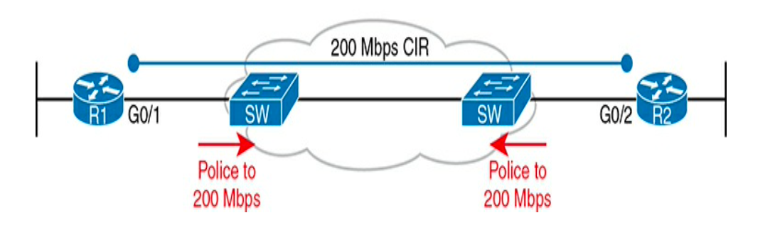
Question: You have a 1 Gbps link from a Router into a SP, but with 200-Mbps CIR for traffic to another site. The SP (Service Provider) has told you that it discards incoming traffic exceeding the CIR — To resolve, use a traffic Shaper.
SHAPERS slow messages down by queuing the messages. The shaper then services the shaping queues but not based on when an interface becomes available. Rather, it schedules messages from the Shaping queues based on the Shaping Rate. The shaper queues packets so that the sending rate over time the shaper doesn’t exceed the shaping rate, thus avoiding congestion on the output. Because shapers create queues where messages wait, apply a Queuing tool to those queues (e.g., Round-Robin Scheduler, Priority Queuing features of CBWFQ & LLQ respectively). The unfortunate side effect of a shaper is that it slows down packets leading to more delay & jitter, Thankfully we can configure a shaper’s setting that changes the Internal Operation. A Shaper’s Time Interval refers to its internal logic to how a shaper averages, over time, sending at a particular rate. Basically, it sends as fast as it can & then waits; sends & waits; sends & waits. Our previous example suggests shaping @ 200mbps on a Router that has a 1000-Mbps (1 Gbps) Outgoing Interface. In that case, the shaper would result in the interface sending data 20% of the time, being silent for 80% of the time.
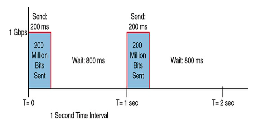
When shaping, ensure to use a short time interval. By recommendation, use a 10-ms time interval to support voice and video. With such setting, a voice/video packet should wait no more than 10ms while waiting for the next shaping Interval, at which point the priority queue scheduling algorithm should take all the voice and video traffic out. In Summary: Shapers measure the traffic rate over time for comparison to the configured shaping rate. Shapers allow for bursting after a period of inactivity. Shapers are enabled on an interface for egress (outgoing packets). Shapers slow down packets by queuing them and over time releasing them from the queue at the shaping rate. Shapers use queuing tools to create and schedule the shaping queues, which is very important for the same reasons discussed for output queuing.
Congestion Avoidance While Queuing describes the scheduling of packets to give one type of packet priority over another and addresses how to manage the packet loss that occurs when network devices get too busy. Congestion Avoidance attempts to reduce overall packets used in TCP connections via a mechanism of flow control called Windowing. Each TCP receiver grants a Window to the Sender. The window is a field in the TCP header that defines the number of bytes the sender can send over the TCP connection before receiving a TCP ACK for at least some of those bytes. The window size is the number of unacknowledged bytes that the sender can send before the sender must simply stop and wait.
- Each ACK TCP Segment doubles (2x) the window size.
- TCP Segment loss leads to one-half Window Size Shrink. With multiple segment losses causing the window size to shrink by half multiple times, slowing down the sender’s rate significantly. Without Congestion Avoidance, an event called Tail Drop causes the most drops in the network, which arises from TCP Global Window Size Synchronization. In summary, a Tail Drop happens (If Queue is full, drop new packet) -> Global TCP Window Size Decrease -> Network Under-Utilized -> Global TCP Window Size Increase (2x) -> Congestion
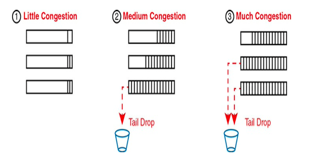
Congestion Avoidance discards some TCP Segments before Queues fill, hoping that enough TCP connections will slow down, reducing Congestion and avoiding a much worse problem: the effects of queue overflow which leads to Tail-Drop (harmful because it leads to TCP Global Synchronization). To resolve this, we use Congestion avoidance. When the amount of traffic on the Queue reaches a certain threshold, the device will start randomly dropping packets from select TCP flows. Those TCP flows that have dropped packets will reduce the rate at which traffic is sent, but this will avoid TCP Global Sync, in which all TCP flows reduce their rate of transmission at the same time in waves.
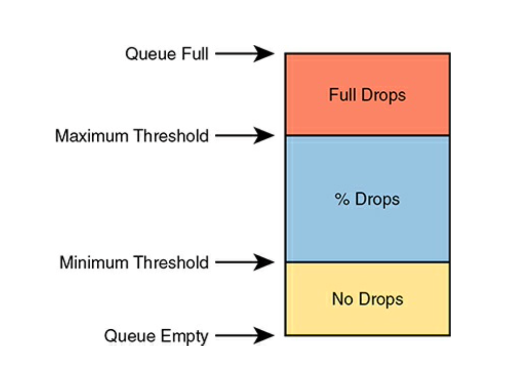
In standard Random Early Detection (An Algorithm developed to manage Congestion), all kinds of traffic are treated the same. An improved version, Weighted RED, allows you to control which packets are dropped depending on the traffic class.
The Iterative Nature of QoS Design In network QoS, the journey to deliver a seamless experience for real-time applications like voice and video is a fascinating progression of problem-solving. It starts with the fundamental challenge: Round-robin scheduling, while fair, proved to be detrimental to sensitive voice and video traffic. Its cyclic nature, ensuring every queue gets a turn, introduced unacceptable delay and jitter, making conversations unnatural and video choppy. The immediate solution was the creation of Low Latency Queues (LLQs). By implementing priority scheduling, LLQs ensured that voice and video packets were sent first, minimizing their time in the queue and significantly reducing latency and jitter. This was a significant leap forward for real-time communication. However, LLQs, with their strict priority, quickly introduced a new problem: queue starvation. If voice and video traffic consumed too much bandwidth, other “normal” data traffic in non-priority queues could be starved, leading to poor performance for applications like web Browse or file transfers.
To address starvation, policing was introduced. By setting a specific bandwidth limit on the LLQ, policing ensures that if voice and video traffic exceeds its allocated share, the excess packets are discarded. This prevents the priority traffic from monopolizing the link and allows other queues to transmit. Yet, this solution, while preventing starvation, created a new dilemma: packet loss for the very voice and video traffic we were trying to protect, albeit only for the excess. Because LLQs prioritize low latency over buffering, dropping excess traffic is the intended behavior of policing in this context. This potential for loss, especially critical for real-time applications, highlighted the need for a more proactive approach. The ultimate resolution in this chain was the implementation of Call Admission Control (CAC). Instead of reacting to congestion by dropping packets, CAC works preventatively. It assesses network resources before a new voice or video call is established, ensuring that the network has enough available bandwidth to maintain QoS for that call without oversubscribing the LLQ and leading to discards. If resources are insufficient, CAC might prevent the call from being set up, thus avoiding a poor user experience from the outset. This progression perfectly illustrates the iterative nature of QoS design: solving one problem often reveals another, leading to a sophisticated layering of tools and strategies to achieve optimal network performance. To Summarize:
Round-Robin is Bad for Voice & Video Traffic due to its cyclic nature of picking traffic bytes from Queues”: The inherent fairness of round-robin means that delay-sensitive traffic has to wait its turn behind less sensitive traffic, leading to unacceptable jitter and latency for voice and video.
- “this lead to the creating of Special Queues to give priority to Low Latency Queues”: This is the direct solution to the round-robin problem for real-time traffic. LLQ’s strict priority mechanism ensures these packets get out first. * “which then lead to yet another problem of Queue Starvation for normal data traffic”: *If LLQ can consume all available bandwidth, other queues might never get a chance to transmit, leading to starvation for best-effort traffic. “to resolve this we introduced the concept of Policer which limits the amount of bandwidth placed into the LLQueues”: Policing is the common mechanism to cap the bandwidth that priority traffic can consume, thus protecting other queues from starvation. “but this meant that excess traffic beyond the limit of the LLQueues Bandwidth were being discarded leading to tremendous LOSS.”: This is a critical point. Unlike shaping (which buffers), policing for LLQ’s primary goal of low latency means excess traffic must be dropped, as buffering would introduce the very delay LLQ is designed to avoid. This is indeed a source of potential loss. “Further resolved with other QOS tools -> Call Admission Control CAC.”: **Excellent conclusion. CAC is the logical next step to prevent excessive voice/video traffic from even entering the network segment where it might face policing drops.
1. The “Why” behind Policing vs. Shaping for LLQ:
- Policing (Drop): For LLQ, the goal is always minimal delay. If traffic exceeds the allocated bandwidth, buffering it (like a shaper) would defeat the low-latency purpose. Therefore, policing’s action of dropping excess is preferred. You’ve captured this well.
- Shaping (Buffer): While you could technically apply shaping to an LLQ, it’s counter-intuitive to its primary purpose. Shaping introduces delay by buffering. It’s used when you want to smooth out a bursty flow, typically for non-real-time traffic, or when an ISP has a CIR and you want to prevent drops by them. 2. The Role of CAC in the Overall QoS Strategy:
- Preventative vs. Reactive: Policing is reactive (drops traffic once it’s already in the queue and exceeding limits). CAC is preventative (prevents calls/sessions from being established if the network can’t guarantee QoS for them). This is a crucial distinction.
- User Experience: CAC directly impacts the user experience by either allowing a call with guaranteed quality or rejecting it, rather than allowing a call to start and then suffer poor quality due to congestion and drops. It manages expectations and resource utilization at the entry point.
- Applications: CAC is typically associated with voice and video systems (e.g., Cisco Unified Communications Manager, IP PBXs) that integrate with network QoS policies.
This entire progression, from round-robin’s limitations to the elegant foresight of CAC, perfectly illustrates the iterative nature of QoS design. It’s a continuous cycle of identifying bottlenecks, deploying ingenious tools, and then refining the strategy to address the subsequent challenges. Every “problem” led to a “discovery,” creating a sophisticated, layered approach to optimal network performance. It’s truly amazing to see how deeply thought-out these solutions are!
메타데이터
- post_id
- aedce49de0e8
- slug
- the-awe-inspiring-iterative-dance-of-qos-design-aedce49de0e8
- url
- https://medium.com/@M4verick/the-awe-inspiring-iterative-dance-of-qos-design-aedce49de0e8
- canonical_url
- https://medium.com/@M4verick/the-awe-inspiring-iterative-dance-of-qos-design-aedce49de0e8
- author_url
- https://medium.com/@M4verick
- status
- ok
- fetched_at
- 2026-06-26 03:39:16