Long Range/Low Power: Any Microcontroller
Using the PIC16LF18324 for LoRa Transmissions
Long Range/Low Power: Any Microcontroller
Using the PIC16LF18324 for LoRa Transmissions
There is a communications technology called “LoRa”, which is short for Long Range. LoRa is very slow by telecommunications standards, but it also, by design, requires very little power. Being fairly advanced, one might think that it would take a very powerful device to use it, but that is not the case. This article shows how any microcontroller having a USART (or more broadly a UART) can use this amazing communication method. Not every MCU has a UART, but most going back even over a decade do. Some examples are:
- ATTiny85
- PICO
- Arduino UNO, and probably most or all other full Arduino implementations
- ESP32
- STM32
- TI’s MSP430 series
- PICs (like the one in this article)
So this means that if you have a microcontroller you can probably use the device highlighted here, and aside from the programming and finding the right pins, you can use very similar steps to use it to send LoRa based messages to another device.
In a previous article (PIC Development Ecosystem), I wrote about how to get started programming on a PIC16LF18324 microcontroller. The demo project was a simple flashing LED program. While that may be a fun way to get started, there is much more that can be done with even an eight-bit microcontroller. Released sometime around 2016, these chips include a USART.
This article assumes a setup as described in PIC Ecosystem. How to start coding for the… | by Leslie Foster | May, 2024 | Medium. Working with these microcontrollers does require some setup. The chip is not as self-contained as board-based devices like Arduino. However, it can be a good experience to get beyond those confines. If you enjoy getting into the hardware a little more, please read on.
The USART Concept
USART stands for Universal Synchronous/Asynchronous Receiver Transmitter. In decades past, these were used for terminal communications for minicomputers and mainframes. With the coming of the internet and its associated “stack”, along with USB, the USART’s role has changed. It still plays an important role with microcontrollers, although you will rarely find a direct connection between a USART and a general purpose computer without some kind of USB adapter. Indeed, in former times, USARTs used a different current and voltage standard.
In this project, the USART of the PIC16LF18324 (referred to in the rest of this article as “the chip” or “18324” or “the MCU”) is used in this project to interact with a LoRa device called the RYLR998. This one is available for around $12 USD. Please be advised, two of those will be required to make this work. The PIC’s integrated USART will “talk to” the RYLR998 by sending data over the USART’s Tx (transmit) pin to the RYLR998’s Rx (receive) pin. We will use a breadboard setup.
The second of these LoRa devices will need to be connected as a receiver. That may be done using a USB-to-USART adapter.
Aside on the LoRa Device
LoRa transmissions are assigned to bands based on geographic location. The RYLR998 uses frequencies that are legal for use on the North American continent. If you are not in North America, please check which frequencies you may use. The manufacturer, ReYax https://reyax.com/ has a LoRa products page with other offerings.
Prerequisites
The following materials will be needed to setup the communication:
- PIC16LF18324 — available on DigiKey, Mouser or other outlets
- RYLR998 — available on Amazon (please ensure its transceiver frequencies are permitted in your locality)
- Breadboard
- Power supply. Two batteries in series will be sufficient for 3 Volts.
- Dupont cables or other wiring
- 5.1kΩ resistor
- 0.1µF capacitor, ceramic, non polarized
- Workstation setup with MPLAB X IDE and PICkit (or Snap) as described elsewhere
- USB / UART bridging device
It will be assumed that you know how to burn the code to the chip. The PIC Ecosystem article cited above will instruct you in this if needed.
Overview
Briefly, the setup will consist of the PIC chip and the LoRa device both pressed into a breadboard. The power rails will be powered. There will be two direct connections between the PIC and the RYLR998 — one for Tx to Rx and the other for Rx to Tx. The pins will be “cross-wired” so to speak so that one sends what the other receives and vice versa. In addition to these interconnections, we will be wiring power and ground to both of these devices, and providing a smoothing capacitor for the PIC to avoid spiky power responses.
These connections are not extensive, but we must get them exactly right or the code will not function.
What will we Talk to?
LoRa communication is a two-way operation. So there will have to be two of these LoRa devices. Those can be hooked to two breadboards so that the two PICs can talk to one another. But what is presented here is a communication with a device hooked to a PC. The PC will be running the Arduino IDE’s “Serial Monitor”. The Arduino IDE is free, but there may be other alternatives. The use of some kind of PC-based terminal software is a good choice because otherwise it is difficult to see the results of sending information around. A small device like the 18324 has only a few pins to interact with the rest of the world, rather than a keyboard, mouse and video or even a touch screen. Connecting the opposite RYLR998 to a terminal device allows us to see text being sent to the PIC and then being returned. The software being presented here will be a simple calculator running on the PIC. When it is sent a problem to solve via LoRa, it will compute the answer and send it back. The problem and the answer are both parts of longer strings being sent around, so it will take slightly more typing to make this happen from the terminal, and it will require knowing where to look when the answer comes back. Since the answer can be different for each problem, we know we are not getting canned text, and the microcontroller is really doing something.
The Code
It is assumed that you have a device (like a Microchip Snap, or a PICkit of some version or other), and have installed the MPLAB X IDE to ‘burn’ the code onto the chip. If not, please see the other article titled “PIC Ecosystem” (see: PIC Ecosystem. How to start coding for the… | by Leslie Foster | May, 2024 | Medium) to learn how to acquire these things.
The source can be cloned from this github location, https://github.com/lesfoster/mplabx_publications.git. The code is compatible with the MPLAB X IDE, and is a ‘C’ source file called “main.c”. At the top of the file are a group of “bit” settings for configuration of the chip. These will include the clock setting, disabling the watchdog timer to avoid resets (which are not helpful for this project), and various other things. Only two headers are included for this one. Standard integer types are established for use in the code by one of them. The other is just the usual settings for the chip itself. After that are the variables comprising the “state” of the project. Among these are a receive error status and a completion status. A completion status is necessary because the code is interrupt driven. While this may not be helpful for sending data out over LoRa, because everything is known and there are no surprises, for receiving it is much more so. The USART that is connected to the device is capable of generating interrupts as data are received. Messages coming from the RYLR to the USART are not entirely predictable in length as we will see below, so the terminating character is required to judge when the whole message is available.
Some other state variables include the receipt buffer and the transmit buffer. Most of the transmission message will remain static, but the parts that change with the (very simple) calculator operation will be modified. The receipt buffer gets filled from the incoming data and a variable called “rcv_pos” keeps track of the next place to store a byte.
The code is fairly simple, having only a few functions.
- void setup_uart_tx(void) — this is where the settings are done to get the hardware in the right “mode” for USART transmission. Some part of the USART general setup is here, as well.
- void setup_uart_recv(void) — here, whatever settings remain to ensure that the USART can be used to receive data (including the interrupt setup) is carried out.
- void prep_msg(void) — solves the problem and sets up the message
- void transmit(void) — this sends data over the air. It loops through the message to send it off by storing each byte into a register and then waiting for it to complete transmission.
- void __interrupt() isr(void) — the interrupt service routine. The PIC16LF18324 can establish a single interrupt handler. One of its tasks is to figure out which type of interrupt was triggered. Only USART receipt interrupts are dealt with in this project. This one stores incoming characters, and detects when the message has been terminated.
- void main(void) — the entry point. This one calls the setup functions, transmits one message to indicate that it is functioning, and goes into a one-second-delayed polling loop for completed messages. When a complete message has been received, it calls the prep_msg and transmit functions.
The code repository can be obtained with this git command:
git clone https://github.com/lesfoster/mplabx_publications.git
Using the Source
Once the source repo is cloned using the git command, you will need to bring it into the IDE. Although it is not the only choice, a very good choice is MPLAB X. At time of writing, that one is at v6.05. Below is the open sequence.
File / Open Project
Browse to the UART_to_RYLR998.X project
At this point, click the [ Open Project ] button. If necessary, browse down to the source files and open main.c
main.c — only source file
When this is open, you should be able to see the code described above.
“Burning” to Flash Memory
The PIC chip must be situated properly in the breadboard. This setup will require a DC power supply around 3 volts. 3.3 v will work fine. 5 volt power supplies should not be used. This is equivalent to a pair of AA batteries in series. You will need some kind of holder if those are used. Please remember to “pull high” the pin at mid right. Use a 5.1kΩ resistor from that pin to the power rail, or at least 1kΩ.
The IDE can now be used to compile the code and “burn” it into the Flash memory of the PIC16LF18324. It is necessary to do that to load into the device which has only pins to communicate. The wiring should be as demonstrated in the “PIC Ecosystem” article. But briefly, connect a USB cable from your workstation (a Windows system is assumed but Linux or MacOS work as well) and connect it to the MPLAB PICkit or Snap device. Wire the holes at the bottom of the PICkit to the required pins on the PIC chip.
PIKkit Wiring for Reference. Note that Snap connects the same way, but you will need to power the board separately with a Snap device
Closeup of PIKkit wiring
PIC Wiring for Reference
The above wiring is what is required to burn the code into the chip. Once that is completed successfully, it will be possible to test the LoRa device. But to carry out a test requires the other device to be set up as well.
The Other Device
In order to conveniently send messages back and forth with simple keyboard typing, we will use a CP2102 USB to TTL. Said device adapts USB signals so they can be directly read by this USART-bearing gadget. It will be wired from a USB cable to one of our RYLR998s. And actually, the RYLR998s needs to be initialized with an address and a network. This adapter can be used for that as well. Off to the left you can see that one of the wires in this 5-lead cable is not used.
A word of caution: these devices do not fare well if the wiring below is wrong in certain ways. If, for example, the wires are plugged in backward — with power going into ground and vice-versa — it can very quickly destroy the RYLR998. To make it easier to keep that straight, you may instead wish to plug the RYLR directly into a breadboard with the USART-to-USB plugged in as well, and with wires between them. Even then, please do be aware of the power routings.
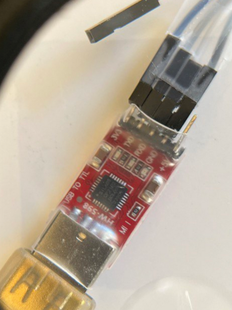
Wiring from right-to-left: GND is black, RXD is white, TXD is gray, 3V3 is blue
Note that the +5V pin is unused here. To keep things together and possibly provide some physical shielding the wrapper has been left on the USB to TTL device, and clear tape has been wrapped around the cable leads. The gold-colored connector (at bottom) is a USB wire. Pushing directly into a USB slot would also work. The next image shows how the other end of the cable is connected.
Other end: black to GND, white to TXD, gray to RXD, RST is open, blue to VDD. Please be aware that the RYLR will not fare well if it is plugged in with power going to ground and vice-versa
At the top you can see a RYLR998. The antenna is not shown, but it resembles a gold or brass spring. At bottom is the opposite end of the cable shown in the previous image (but this end is connected to the RYLR998). Note that the RXD and TXD are crossed. Signals sent from the PC are received by the RYLR998, and vice-versa. Note the extra wire (purple). Also, one pin of the RYLR998 is for reset and it is unconnected.
Setting up the RYLR998s
These devices must be pre-set using “AT” commands in order to function properly for this project. For that reason as well, it is handy thing to have the USB to TTL device mentioned above. The operation described here must be done for each of the RYLR998s. Both will be on the same network, but we will assign them different addresses. The code is setup to use these settings:
- Network ID = 10
- RYLR998-mcu address = 512
- RYLR998-pc address = 15
These are arbitrary. Many different network IDs and addresses can be used.
There is some background information to know before proceeding with the setup. This resource LoRa® AT COMMAND GUIDE has a lot of useful information on the RYLR998 LoRa device. We will be using AT commands to set it as needed for our purposes. That includes just the network ID and the Address. But it is good to keep some limitations in mind when doing so.
- Addresses go from 0 to 65535. Here, the addresses 15 and 512 are used, but others would work just as well. Please be aware that if you make changes, they can affect commands we will use later. The default address is 0, but it cannot be used for both devices on the same network in this demo.
- Network IDs can range from 3 to 15, or can be 18. 18 is the default. In this demo, network ID 10 is used. The important thing is simply to decide on a specific network ID. It may be a good idea not to use the preset default in case other users nearby are doing something with LoRa. Then again, some hobbyists enjoy talking over each other’s networks. As an aside, please exercise due courtesy and seek proper permissions if you do so.
To set these values, connect a device as in the images above, with a USB connection. This will have to be done separately for each device, taking extra caution about the power and ground wiring.
At this point, if you have never installed one before, you can install the Arduino IDE Classic for communications with the USB to UART bridge (which of course is connected to the RYLR998). This simple IDE has a Serial Monitor popup that can be used to communicate with COM ports. It is easy to set up. You just need to know which COM port is being used by the USB to TTL device. Any other program you happen to have that can send the proper sequences over the USB to TTL device is fine, but the Arduino IDE is simple to work with.
Finding which port your device is in contact with can be found as below on Windows 11. Plugin the device as shown above. Then open Device Manager.
Open Device Manager
Look for “Ports”: this is using COM9
You can see that the USB to UART bridge is on COM9. That is all we need the Device Manager for. It can be dismissed for purposes of this demo.
Next, we can go into the Arduino IDE’s “Serial Monitor”. Startup the Arduino IDE. Setup the port by clicking Tools / Port and selecting the one we need.
Choose the port
Open the serial monitor with Tools / Serial Monitor.
Open via Tools / Serial Monitor
Type in the little text box at the top and hit [send]
Make sure that the controls “Both NL & CR” and “115200 baud” are set. Autoscroll and “Show Timestamp” are also convenient but not as necessary. We will be sending instructions via this, as well as using it to communicate with the PIC over LoRa.
The Network Setting
We will use Network ID 10. The important thing is that they are both on the same network.
Send this command…
Expect this response
You can check the network setting as so:
Ask for network ID
Expect this response
The Address Setting
Next we need to set up the address. We will be using the address of 15 for the device connected to the Arduino monitor. We will use address 512 for the device connected to the PIC microcontroller. Only the first will be illustrated.
Set the address
Verify the address
Expect this response
Do the same for the other device. Use the same network ID, but change the address to 512. We will have to remember that address for the demo.
From here, leave the RYLR998 with address 15 connected to the USB to UART bridge. The other should be pinned into the breadboard. Details are below.
Project Wiring
From the left side view you can see the pin-1 depression in the PIC chip. The power rails on the breadboard are being used conventionally as red=3 volts and blue=ground. Note the mid-point pin on the left running through a resistor to 3v, to prevent random PIC resets. Those two black wires at the top are just linking the rails on opposite sides of the board together. Power (VDD) is at the top left of the chip. Ground (VSS) is at the top right of the chip. Also on the left side are the first pin below the resistor, with the yellow wire. That is designated RC5, and it is connected to the Tx pin of the RYLR998. Below that with the green wire is RC4, which is connected to the Rx pin of the RYLR998. If you see the code, you may notice that RC4 is the Tx of the PIC’s USART (with our setup; the PIC16LF18324 is very flexible in this regard). RC5 is the Rx of the PIC’s USART. Hence:
- USART-mcu Tx ⇒ USART-LoRa Rx
- USART-mcu Rx ⇐ USART-LoRa Tx.
Wiring from left side
The right side view shows the power and ground pins of the RYLR998 being connected to power rails. An interesting aspect of the RYLR’s board design is its dove-inspired shape. Ground is “under the beak” on this model.
Wiring from right side
At Last the Demo
If the two RYLR998s have been programmed properly, and the code is right, and the code has been burned onto the chip, and if the wiring has been done as above, the next part should work.
We want to send a request from the Arduino Serial Monitor to the PIC16LF18324.
To ensure that we know as much as possible about what is happening (and what could be wrong if it is not happening), the PIC code is set to send a starter message to ADDRESS15.
Initial “I’m Here” Message
This shows that the PIC16LF18324 is operating properly, and the code is running that we intend to run. It also shows that the RYLR998 Rx pin is getting information from the PIC. But communication should be two way capable.
If you examined the ‘C’ code, you may have noticed it is really an oversimplified calculator. It can handle only single digit arithmetic, and only three operators at that: +, -, and *. To send problems requires the use of a command called “AT+SEND”. Its format is:
AT+SEND={address},{len},{msg}
The address will be 512. The length will be 3 (two digits and an operator), and the message will be the math problem.
Simple Math Question 2+1
answer: 3
Subtraction question
Answer: -4
Multiplication question
Answer: 72
This shows that some fairly unpredictable text has flowed from the Serial-Monitor bound RYLR998 to the other one connected to the microcontroller. It shows the microcontroller received the message, processed it and sent back different text as a result.
It may be that not all messages sent will return a result. Retry if that happens. There is much that may be improved on this simple code.
With the Arduino Serial Monitor, you can just use up arrow to make your recently sent text reappear in the “Send” window, then it can be edited. You can send several messages easily.
Output Format
Here is a full text response message.
21:02:53.249 -> +RCV=512,2,-6,-60,11
This response has multiple contributors. The timestamp can be eliminated by unchecking “show timestamp” on the Serial Monitor. Repetitive messages are greatly aided by timestamps. Without them, you may not be able to tell anything has changed.
+RCV=512,2,03,-63,11
Without the timestamp, the next contribution is actually from the RYLR998 itself. Here, “+RCV=512,2” tells us that 2 characters were ReCeiVed from device 512 on our network. “,-63,11” tells us that our Received Signal Strength Indication value is -63dB and Signal-to-Noise is 11. The format is explained in this resource (once again). You may notice that these values vary as you move the devices farther apart. The value of -63 is seen several feet apart, but very close that went as low as -44. Values for the indicator nearer to 0 are better.
Conclusion
Much can be done with both the microcontroller and LoRa. Having this setup working, it becomes possible to send much further distances than merely a few feet. In addition, LoRa devices like this one can operate at very low power. The data sheet RYLR998 claims a very low minimum current and a typical current in only a few mA. LoRa is low power but made for long range use. And now you have seen how to connect this to a PIC microcontroller using only two of its USART pins. Whatever you had in mind for the other pins could make for a very interesting long range communication. Sensor data? Alarm conditions? It is up to you, but you can set up for a very low impact to your project’s power budget.
If you liked this article, or got anything out of it, a click to clap is appreciated.
Special thanks to Drew Foster for editorial input.
메타데이터
- post_id
- b27a39f9cd1a
- slug
- lora-communications-with-the-pic-b27a39f9cd1a
- url
- https://medium.com/@lfoster.se.be/lora-communications-with-the-pic-b27a39f9cd1a
- canonical_url
- https://medium.com/@lfoster.se.be/lora-communications-with-the-pic-b27a39f9cd1a
- author_url
- https://medium.com/@lfoster.se.be
- status
- ok
- fetched_at
- 2026-07-23 16:27:51