High Voltage Underground Cable: Engineering Reliable Power Below the Surface
As urban density increases and aesthetic concerns push transmission lines out of sight, high voltage underground cable has become the…
High Voltage Underground Cable: Engineering Reliable Power Below the Surface
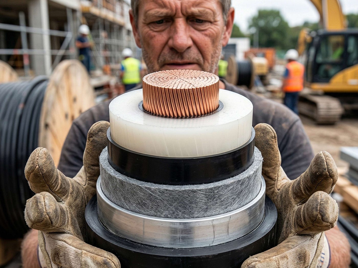
As urban density increases and aesthetic concerns push transmission lines out of sight, high voltage underground cable has become the backbone of modern power distribution. Unlike overhead lines that benefit from open-air cooling and straightforward visual inspection, underground cables operate in a hidden environment where thermal dynamics, mechanical stress, and moisture ingress dictate system longevity.
Designing and installing high voltage underground cable systems requires a fundamentally different engineering approach than overhead alternatives. When done correctly, underground transmission offers superior reliability, reduced right-of-way costs in urban areas, and near-total immunity to weather-related outages. When done poorly, it leads to premature failure, costly excavations, and extended downtime.
Thermal Performance: The Hidden Constraint
The single most critical factor in high voltage underground cable design is thermal resistivity of the surrounding soil. Unlike overhead conductors that dissipate heat freely into the air, buried cables rely on the surrounding medium to carry heat away from the conductor.
When soil dries out due to prolonged cable operation, its thermal resistivity can increase dramatically — a phenomenon known as thermal runaway. This is why proper backfill materials are essential. Engineered thermal backfill, such as fluidized thermal backfill (FTB) or sand-cement mixtures, ensures consistent heat dissipation regardless of seasonal moisture variations.
Ampacity ratings for high voltage underground cable are not fixed values. They must be calculated based on soil type, burial depth, ambient ground temperature, and the proximity of other cables. Parallel circuits that appear to offer redundancy can actually derate each other significantly if spacing is insufficient.
Mechanical Protection and Installation Methods
Once buried, **armored high voltage underground cable** becomes difficult to access for repairs. This reality makes mechanical protection during and after installation a top priority.
Direct burial is the most economical method, but it leaves cables vulnerable to future excavation damage and rodent activity. For critical circuits, installing cable in concrete-encased duct banks provides the highest level of mechanical protection. This approach also allows for future replacement without trenching, as individual cables can be pulled through ducts.
Horizontal directional drilling (HDD) has become increasingly common for high voltage underground cable installations crossing rivers, highways, and environmentally sensitive areas. HDD minimizes surface disruption but introduces unique risks, including pulling tension exceeding manufacturer limits and damage to the cable jacket during borehole navigation. Proper pulling calculations and real-time tension monitoring are non-negotiable for HDD projects.
Water Ingress: The Silent Failure Mechanism
Water and high voltage electrical systems do not mix. In high voltage underground cable, water ingress through jacket damage or improperly sealed terminations leads to a cascade of failures.
Water treeing — a phenomenon where microscopic channels of moisture degrade polymeric insulation over time — remains one of the leading causes of premature cable failure. Modern cables incorporate water-blocking technologies such as swellable tapes, impermeable metallic sheaths (lead or aluminum), and longitudinally water-blocked (LWB) designs to mitigate this risk.
For critical infrastructure, specifying a high voltage underground cable with a corrugated aluminum or copper sheath provides both moisture protection and a reliable fault current path. While these constructions increase initial cost, they dramatically extend service life in wet or high-water-table environments.
Terminations and Joints: The Weakest Links
No high voltage underground cable system is stronger than its accessories. Terminations and joints are where field assembly occurs, and they represent the highest risk points for early failure.
Prefabricated slip-on joints and heat-shrink or cold-shrink terminations have largely replaced field-taped systems due to consistency and reduced installation time. However, even the best accessory requires meticulous surface preparation, proper torqueing of connectors, and cleanroom-level contamination control during installation.
For long cable runs, joints must be spaced strategically to manage pulling tensions and accommodate shipping limitations. Each joint introduces a potential failure point, so minimizing their number while respecting practical installation constraints is a key design objective.
Testing and Commissioning
A newly installed high voltage underground cable should never be placed into service without comprehensive testing. Withstand testing — typically using very low frequency (VLF) or resonant AC test sets — verifies that the insulation system has survived installation stresses without damage.
Partial discharge (PD) mapping has emerged as the gold standard for commissioning new circuits. PD testing can identify localized defects at joints or terminations that withstand voltage testing alone might miss. Establishing baseline PD levels during commissioning provides a reference for future condition assessments.
Lifecycle Considerations
The upfront cost of high voltage underground cable installation typically exceeds overhead alternatives by a factor of three to eight times, depending on terrain and urban constraints. However, the lifecycle calculus often favors underground in dense urban environments where overhead rights-of-way are unavailable or prohibitively expensive.
Maintenance for underground circuits is less frequent but more invasive. While overhead lines require routine vegetation management and insulator cleaning, underground cables demand periodic thermal monitoring, sheath voltage testing, and — in some cases — dielectric loss measurements to track insulation health.
Forward-thinking utilities increasingly deploy distributed temperature sensing (DTS) using fiber optics embedded in the cable or installed alongside it. DTS provides real-time thermal profiles, enabling dynamic rating adjustments and early warning of localized overheating.
Conclusion
High voltage underground cable systems represent a significant investment in infrastructure resilience. Success lies not in any single component but in the integration of proper thermal design, robust mechanical protection, moisture mitigation, quality accessories, and rigorous testing. When these elements come together, underground transmission delivers decades of reliable service with minimal visibility — exactly as intended.
Frequently Asked Questions (FAQ)
1. What is the typical lifespan of a high voltage underground cable? A properly designed and installed high voltage underground cable can operate for 40 to 50 years or more. Lifespan depends heavily on thermal loading, soil conditions, moisture exposure, and the quality of terminations and joints.
2. How deep should high voltage underground cable be buried? Burial depth varies by application, but typical direct burial depths range from 24 to 48 inches. Duct bank installations often have less cover but are protected by concrete encasement. Minimum depth requirements are typically specified by local codes and the **National Electrical Safety Code (NESC)**.
3. Can high voltage underground cable be repaired if damaged? Yes, damaged sections can be repaired using factory-manufactured splice kits. However, repair requires excavation, removal of the damaged segment, and installation of field-assembled joints. Repairs are considerably more expensive and time-consuming than overhead line repairs.
4. What is the difference between VLF testing and PD testing for underground cables? VLF (very low frequency) testing applies an AC voltage at reduced frequency to verify insulation withstand capability. PD (partial discharge) testing detects microscopic electrical discharges within insulation defects, identifying potential failure points before they lead to breakdown.
5. Why is thermal backfill important for underground cable installations? Thermal backfill ensures consistent heat dissipation from the cable to the surrounding soil. Poor backfill can lead to thermal runaway, where dried-out soil insulates the cable, causing temperatures to rise until the insulation fails. Engineered backfill maintains stable thermal properties regardless of moisture conditions.
메타데이터
- post_id
- b4018aa3f930
- slug
- high-voltage-underground-cable-engineering-reliable-power-below-the-surface-b4018aa3f930
- url
- https://medium.com/@zackme/high-voltage-underground-cable-engineering-reliable-power-below-the-surface-b4018aa3f930
- canonical_url
- https://medium.com/@zackme/high-voltage-underground-cable-engineering-reliable-power-below-the-surface-b4018aa3f930
- author_url
- https://medium.com/@zackme
- status
- ok
- fetched_at
- 2026-06-21 07:44:09