High DC Current Sensing with a Raspberry Pi
Do you want to measure high DC current (and 0–26V) using a raspberry pi or similar, inexpensively? 10 amps? 100 amps? Maybe 500A?
High DC Current Sensing with a Raspberry Pi and Python
Do you want to measure high DC current (and 0–26V) using a raspberry pi or similar, inexpensively? 10 amps? 100 amps? Maybe 500A? Enough of the cheesy salesman talk.
My solution is to ‘hack’ an INA219 current sensor by removing (desoldering) the 0.1 Ohm resistor and ‘replacing’ it with a high-current shunt. Don’t worry, it’s not very difficult.
The INA219 current sensor is a ‘shunt’ itself, which works by measuring the (minute) voltage drop across the 0.1 Ohm resistor built onto the board. It then uses this to calculate the current flowing through the resistor using Ohm’s Law (V = IR | V = Voltage (V), I = Current (A) and R = Resistance (Ω)). So, if you need to measure higher current than the 3.2A that the unmodified INA219 sensor can handle (like I did), we can leverage the high precision voltage sensor across the 0.1 Ohm resistor and connect a high-current shunt (resistor) instead. The best thing is that we can make these modifications and still use the available software libraries as they were intended.
What this guide will do:
- Demonstrate the hardware modification to the INA219 sensor (desoldering a surface mount resistor)
- Calculate the new constants required for use of the modified sensor in a program
- Provide demonstration code in python to get you up and running
Required Components:
- INA219 Sensor
- 10–500A Shunt (I will use a 100A shunt as an example)
- Raspberry Pi (any version)
- Breadboard + jumper cables (if desired)
- Soldering Iron + tweezers/screwdriver
Hardware Modification
The left image is an un-modified INA219 sensor with the peripherals (headers & screw-in cable connectors) soldered on — note the R100 resistor soldered to the board in the middle. The right image is the modified sensor with the R100 removed — that’s what we want, and I’m sure you can do a better job of desoldering than I did…
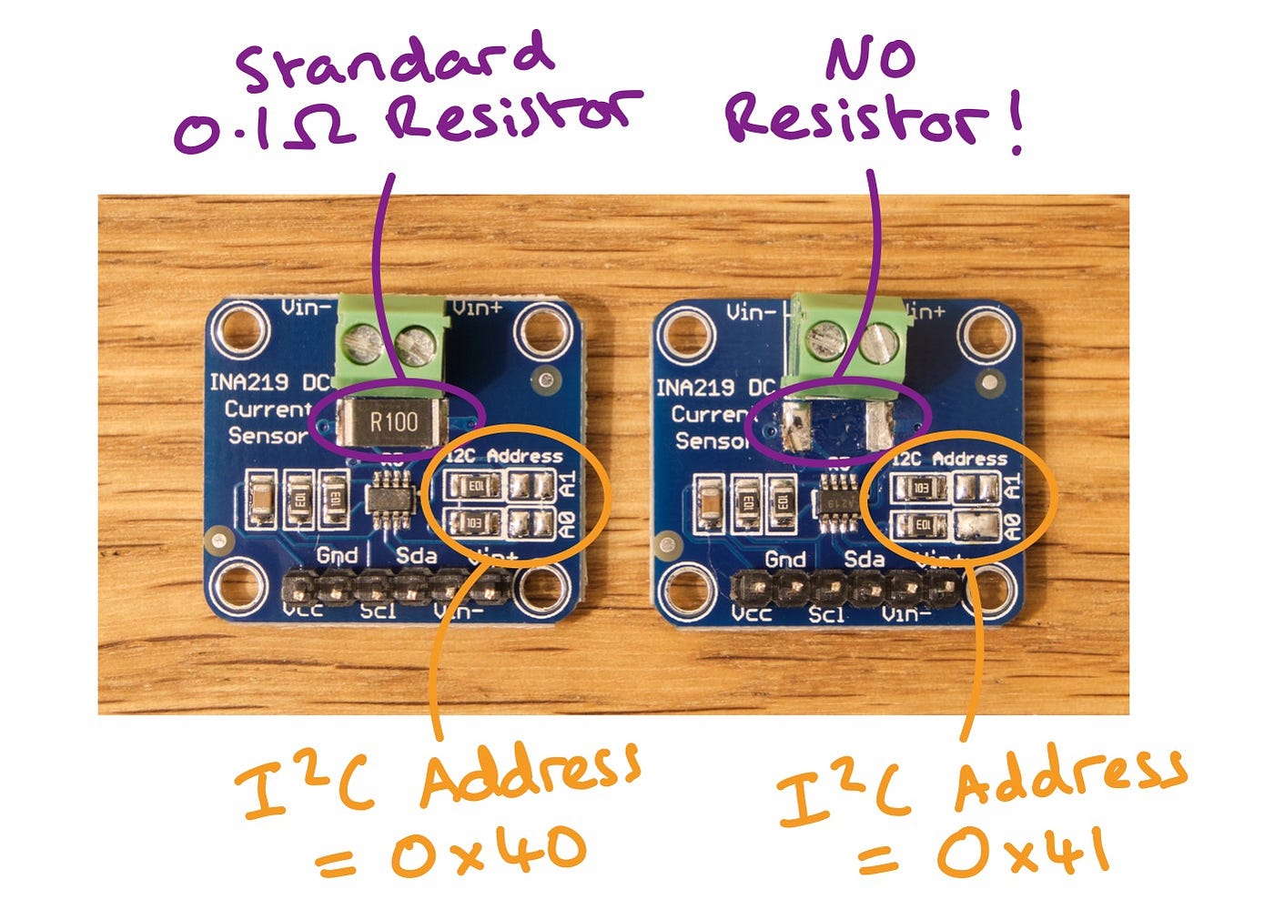
The unmodified INA219 sensor on the left and the modified sensor on the right. The I2C addressed have also been modified. © Seb Hulse
Disclaimer before we go on — I am no soldering or electrical hardware modification expert and of course, soldering irons can be dangerous and should be treated with care. Some basics of using a soldering iron — make sure to use a well-ventilated area to avoid breathing the smoke and hold your sensor in a grip/vice so you can keep your fingers away from the soldering iron tip while desoldering.
I’d recommending viewing other desoldering guides for more concrete tips if you’re unsure. But, I found that it helps to get your iron as hot as you can, to hold the tip on one side of the resistor and have a small screwdriver or pair of tweezers to prize the resistor away from the board when the solder melts enough. It may initially only move marginally, but the job can be finished when the same is done to the other side. Thats the hard bit done. Now we can connect our circuit up.
Circuit Connection
See the below circuit diagram to connect the INA219 to the raspberry pi and shunt, with the shunt in series with a load so that the current can be measured.
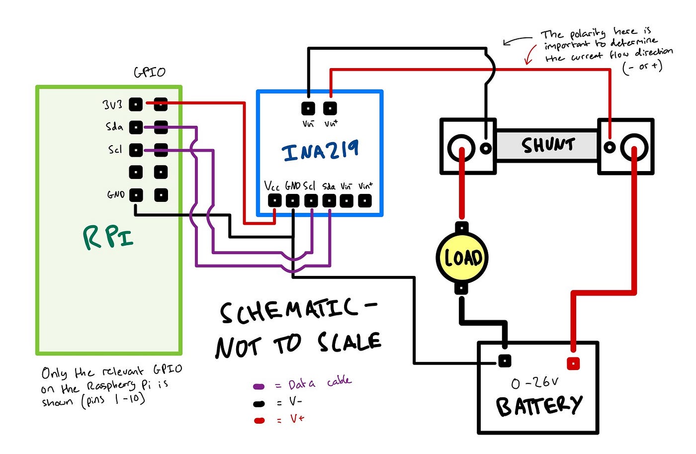
A circuit diagram to connect an INA219 Sensor to a Raspberry Pi and shunt, with the shunt in series with a load. © Seb Hulse
Note three things from this schematic — 1. It is not to scale — 2. Only the relevant GPIO for the Raspberry Pi is shown (pins 1–10), see here for an accurate schematic of the pins and — 3. The polarity with which you connect the shunt to the INA219 sensor will determine the direction of current which may be important if you’re trying to measure the power input/output of a solar/battery system for example. The data cables are shown in purple, Negative/GND are black and Positive are red.
To connect the INA219 to the raspberry pi, we need to use the two I2C interface pins (GPIO 2 (SDA) and GPIO 3 (SCL) — pin 3 and 5 on the board), 3V3 power and Ground — note that the two I2C pins can be used for multiple I2C devices, provided that the devices each have unique addresses and are connected in parallel. This I2C address can be set to allow up to 4 simultaneous INA219 sensors on the interface by bridging the A0 and A1 points as below.

The individual I2C addresses for 4 simultaneous INA219 connections to one I2C bus. © Seb Hulse
GND on the INA219 is connected to the GND of the pi so that additional devices can use the bus if required. The shunt can then be connected to the INA219 sensor simply by connecting the V+ and V- of the INA219 to either side of the shunt itself. You can either use the connections on the screw-in connector (on the INA219) or the header connections, they’re both wired in parallel to the same place. There are usually smaller screws on the shunt that can be used to secure the wires in the appropriate places. The final thing to do is to connect the ground of the raspberry pi to the V- of the circuit being measured. This allows us to use the bus voltage measurement function of the INA219 so we can calculate the power in Watts (P = VI | P = Power (W)) flowing through the circuit. Note that the maximum bus voltage that the INA219 can measure is 26V.
Constant Calculation
Before we jump into the code, it’s important to see how we’ve changed the electrical circuit. As i’ve mentioned, the R100 resistor that we removed had a resistance of 0.1 Ohms. We’ve essentially just replaced that resistor with another, which has a smaller resistance to allow us to measure higher currents. We need to know what the new resistance is so the INA219 sensor can accurately apply the V = IR logic. The new circuit shunt has been designed to show a particular voltage drop when the maximum current is flowing through it. In my 100A example, the voltage drop is 75mV when 100A is flowing through it, and this is engraved on the shunt itself. The shunt also shows that the measured values will be correct to approximately +-0.5%.
The resistance of the shunt is:
R = V / I = 0.075V / 100A = 0.00075 Ohms (0.75 milli Ohms)
Which we can use in our code. Note that the power loss over this shunt at 100A can be calculated with P = VI.
P = 0.075V * 100A = 7.5W
So, the system should be designed to allow for 7.5W of heat dissipation from the shunt when running at 100A.
Python Code
Now all we have to do is get some code up and running. I will demonstrate using a Raspberry Pi running Raspberry PI OS (Raspbian). Make sure it’s up to date by running:
sudo apt update && apt upgrade -yThen we can install the python package pi_ina219 created by chrisb2 which we can find on Github here and that can be run on either python 2 or 3. I will use python 3 in this example. This is a great package that has some auto — gain functionality which may come in handy to some. We will stick to the most manual method since we know the required values and can get the most predictable results this way.
To install on the raspberry pi:
sudo pip3 install pi-ina219We will adjust the Advanced — Manual Gain, High Resolution example given by chrisb2 as follows. Firstly, the SHUNT_OHMS constant is the resistance of the shunt that we calculated above. In the example case of a 100A shunt, this value is 0.00075 Ohms. Also, the MAX_EXPECTED_AMPS in our case will be 100A.
To configure the ina object, we will specify the bus voltage range to be 16V using RANGE_16V (to be suitable for a 12v system, for example). We will also specify the GAIN of the 'shunt voltage drop' sensor to be GAIN_2_80MW. This is because the max voltage drop we expect over the shunt is 75mV - 80mV can encapsulate this. The library also provides higher voltage drops (up to GAIN_8_320MV) if you consult the documentation. GAIN_AUTO can also be used (default).
[embed]
Note that in this example, if the current ‘overflows’, current and power values will be missing.
If you have more than one INA219 sensor and have changed the physical I2C address on the circuit board, the address of the individual sensors can be set like so:
ina = INA219(SHUNT_OHMS, MAX_EXPECTED_AMPS, address=0x41)Once you’ve connected the circuit up, installed the required dependancies and run the above code, you should get some output that looks something like this:
Bus Voltage: 12.732 V
Bus Current: -27.439 mA
Power: 304.878 mW
Shunt voltage: -0.020 mV
If continuous readings are required, the function can of course be encapsulated in a while True block, or the Raspberry Pi can run the script from start as a Cronjob in the background.
These output values are from my battery-solar system wherein I’m using two 100A shunts to measure both the battery in/out and the solar production on a Raspberry Pi Zero. I can then use these values to derive the load. I’m also running an InfluxDB database and Grafana server from the Pi (I know, poor pi zero!) but it handles one or two concurrent users well with no problems! If you want to know more, I’ve written a full guide series detailing how to do so:
I hope this guide has provided some value for you and you’re now able to accurately measure some relatively high DC current loads! Not so hard after all :)
Thank you for reading the whole article! It means a lot to me that you took some moments out of your day to consider my ideas :)
I’ve noticed that this post seems to be popular for readers outside of medium (98% external!). So, if you’re not a Medium member but have enjoyed reading along, please consider supporting me by subscribing to Medium via my referral link below. If you do, I’ll receive a portion of your membership fees and it will enable me to write more articles similar to this one. Plus, you’ll gain access to all that the writers of Medium have to offer!
Have a great day!
메타데이터
- post_id
- b535d096cf9b
- slug
- high-dc-current-sensing-with-a-raspberry-pi-b535d096cf9b
- url
- https://medium.com/@sebhulse/high-dc-current-sensing-with-a-raspberry-pi-b535d096cf9b
- canonical_url
- https://medium.com/@sebhulse/high-dc-current-sensing-with-a-raspberry-pi-b535d096cf9b
- author_url
- https://medium.com/@sebhulse
- status
- ok
- fetched_at
- 2026-07-28 14:18:06