MSTP (Multiple Spanning Tree Protocol): VLAN-Based STP Configuration
Hello everyone, welcome back! In today’s post, we’ll be discussing a topic at the CCNP level. I recommend reading my previous posts about…
MSTP (Multiple Spanning Tree Protocol): VLAN-Based STP Configuration
Hello everyone, welcome back! In today’s post, we’ll be discussing a topic at the CCNP level. I recommend reading my previous posts about STP before diving into this one. Now, if you’re ready, let’s get started!
First, let’s understand what MSTP is. As you know, to find the most efficient path and prevent loops in the traffic, we use a protocol called STP. A root device is selected in STP. Now, let’s imagine a large network with different VLANs. In this case, we might want each VLAN to follow a different path. For example, the root device for VLAN 10 could be Switch1, but for VLAN 20, the root device could be Switch4. Each VLAN doesn’t necessarily have to have the same root. This is where MSTP (Multiple Spanning Tree Protocol) comes into play. Now, to make this easier to understand, I’ll directly jump into a configuration example and explain the topic step by step.
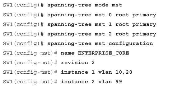
Let’s try to understand the configuration above, step by step.
To activate MSTP on a switch, we use the command: “spanning-tree mode mst” Then, for the interfaces in regions 0, 1, and 2, we specify that SW1 will be the root device. This means that for the regions numbered 0, 1, and 2, we set SW1 as the root. Let’s say we have 15 VLANs, and SW1 is the root switch for 10 of these VLANs. Instead of setting SW1 as the root for each VLAN individually, we divide the VLANs into "instances" such as 0, 1, 2... This allows us to easily configure the root switch for these VLANs by referring to the instance rather than setting each VLAN individually.
One important point to note is that Instance 0 is a special instance. Any VLAN that isn’t assigned to a specific instance is placed in Instance 0, which can be considered as the default region.
After determining which instances will have SW1 as the root using the command “spanning-tree mst … root primary” , we switch to MSTP’s configuration mode from global configuration mode by typing: “ spanning-tree mst configuration ”. Once in this mode, we give our network a name. All switches in the MSTP region will be part of this network. This essentially defines the STP boundaries for the network. Next, we define the MSTP version using the command: “revision 2”. This ensures that all devices in the network use the same version. Finally, we define which VLANs belong to which instances. For example: “instance 1 vlan 10,20" and “instance 2 vlan 99”. This is how the configuration is structured. Now, let’s also look at some configuration examples and wrap up the article.
Priority Configuration:
Now, let’s understand the difference between setting switch-based priority and port-based priority. Switch priority determines which switch will be the Root Switch, while port-based priority is used to decide which path will be preferred.
Switch-Based Priority Configuration:
SW1(config)# spanning-tree mst 0 priority 24576Port-Based Priority Configuration:
SW2(config)# interface gi1/0/1
SW2(config-if)# spanning-tree mst 0 port-priority 64
As you can see, these two priorities serve different purposes. You can configure different priorities for different instances. In this example, we have configured the default instance, Instance 0.
Cost Configuration:
Similarly to priority, we can configure cost either globally for the switch or specifically for each port.
Switch-Based Cost Configuration:
SW1(config)# spanning-tree mst 0 cost 5000Port-Based Cost Configuration:
SW3# configure terminal
SW3(config)# interface gi1/0/1
SW3(config-if)# spanning-tree mst 0 cost 1
Verifying Configurations:
Finally, let’s see how we can verify and check the configurations we’ve made. Use the command:
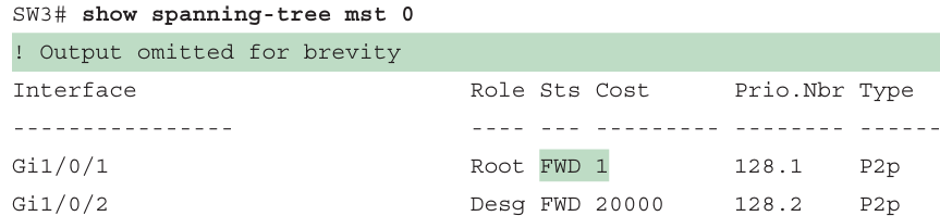
This will show the spanning-tree status for Instance 0.
When making these configurations, there are some important points to be aware of. For example, you cannot assign a VLAN to multiple instances. This would cause confusion because each instance has its own STP, and if VLAN 20 is in both Instance 1 and Instance 2, there will be conflicting paths. One instance might direct the VLAN traffic one way, while the other instance might direct it the opposite way. This creates inconsistency and could cause network issues.
That’s all for today’s article. I hope it was clear and enjoyable to read. If you have any questions, feel free to ask in the comments. See you in the next post, and stay connected with networking!
메타데이터
- post_id
- bb0351bbc896
- slug
- mstp-multiple-spanning-tree-protocol-vlan-based-stp-configuration-bb0351bbc896
- url
- https://medium.com/@mscurious/mstp-multiple-spanning-tree-protocol-vlan-based-stp-configuration-bb0351bbc896
- canonical_url
- https://medium.com/@mscurious/mstp-multiple-spanning-tree-protocol-vlan-based-stp-configuration-bb0351bbc896
- author_url
- https://medium.com/@mscurious
- status
- ok
- fetched_at
- 2026-06-20 20:29:01