Arduino-Powered Lockbox
A Safety Solution for Preventing Drunk Driving
Arduino-Powered Lockbox
A Safety Solution for Preventing Drunk Driving
Motivation
Welcome to my Arduino adventure! Grab a drink (not alcohol) and some patience, now let’s build something cool!
Every year, thousands of college students risk their lives by driving under the influence or walking home late at night after parties, urging a need for effective safety measures. In 2021, incidents related to drunk driving among young adults increased by 10% (Lange). My project combines an alcohol sensor, servo, lockbox, and Arduino to promote safety meaningfully. Instead of creating just another gadget, I wanted to develop something that could genuinely help in real-life situations related to alcohol consumption.
My motivation stems from my college experiences, where I often intervened when friends considered driving while intoxicated, as well as a family member who was seriously injured in a drunk driving accident. These situations ensure why the need for a reliable tool to prevent drunk driving is important. This project aligns with my interest in psychology and its impact on behavior in social contexts. It also connects to my interests in Human-Computer Interaction (HCI), where I aim to explore how technology can enhance safety and awareness.
I hope this project educates people about the dangers of alcohol and encourages responsible choices. I envision this project being used at college parties, community events, educational workshops, or as a prototype for individuals facing DUI penalties who want to avoid using a breathalyzer to start their car. This system could provide real-time data on alcohol levels and potentially be integrated with existing breathalyzer technology.
Components
- Arduino Uno
- MQ-3 Alcohol Sensor
- SG90 Servo Motor
- Jumper Wires (male-to male) and (male-to-female)
- USB Cable
- 6x3x4 Box
- X-Acto knife
- Glue gun
- 9V Battery (optional)
Quick Start
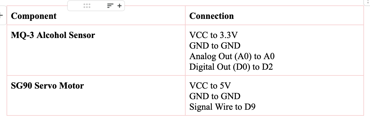
Steps:
Prepare the Breadboard and Connect the Components
Wire the MQ-3 Sensor
Connect the VCC, GND, Analog Output (AOUT), and Digital Output (DOUT) pins as follows:
- VCC pin: Use a jumper wire (male-to-female) to connect this pin to the 3.3V pin on the Arduino.
- GND pin: Use a jumper wire (male-to-female) to connect this pin to the GND pin on the Arduino.
- AOUT pin: Use a jumper wire (male-to-female) to connect this pin to the A0 pin on the Arduino.
- DOUT pin: Use a jumper wire (male-to-female) to connect this to the D2 pin on the Arduino.

Attach the Servo Motor
Connect the servo’s power wires as follows:
- Red wire (VCC): Use a jumper wire (male-to-male) to connect to the 5V pin on the Arduino.
- Brown or Black wire (GND): Use a jumper wire (male-to-male) to connect this pin to the GND pin on the Arduino.
- Yellow wire (Signal): Use a jumper wire (male-to-male) to connect to Pin 9 on the Arduino.

Connect Power to Ardunio
- Use the USB cable to connect the Arduino to your computer.
Upload the Code to the Arduino
- Open the Arduino IDE
- If you don’t have the Arduino IDE installed, download it from https://www.arduino.cc/en/software.
Select the Correct Port
- Go to Tools > Port, and select the port where your Arduino is connected.
- It should look like /dev/cu.usbserial-12345 or COMx on Windows.
Select the Board
- Go to Tools > Board, and choose Arduino Uno.
Copy the Code Below Paste the following code into the Arduino IDE:
- Disclaimer: The MQ-3 sensor part of the code is from ChatGPT.
#include <Servo.h>

Servo lockServo;  // Create a servo object

const int sensorPin = 2;  // Digital output pin connected to MQ-3 sensor
const int servoPin = 9;    // Servo motor connected to pin 9

void setup() {
 Serial.begin(9600);  // Start serial communication
 lockServo.attach(servoPin);  // Attach the servo to pin 9
 lockServo.write(0);  // Start with the box locked at 0 degrees
 Serial.println("System initialized, box is locked (0 degrees).");
}

void loop() {
 int sensorState = digitalRead(sensorPin);  // Read the digital output from the MQ-3 sensor

 // Print the sensor state for debugging
 Serial.print("Sensor State: ");
 Serial.println(sensorState);  // Print 1 (HIGH) if alcohol is detected, 0 (LOW) if not

 // Check the state of the sensor
 if (sensorState == HIGH) {  // LED ON, alcohol detected
   Serial.println("Alcohol detected! Keeping the box locked...");
   lockServo.write(0);  // Lock the box (move servo to 0 degrees)
 } else {  // LED OFF, no alcohol detected
   Serial.println("No alcohol detected. Unlocking the box...");
   lockServo.write(90);  // Unlock the box (move servo to 90 degrees)
 }

 delay(2000);  // Wait 2 seconds before the next reading
}
Upload the Code
- Click the Upload button to upload the code to your Arduino.
Building the Enclosure
You can 3D print a 6x3x4 box or if you’re lazy just take a trip to Micheal’s or Hobby Lobby.
- Cut a hole on the side for the alcohol sensor and for the usb cable. Think of it like carving a pumpkin but way less messy.
- A tip to make ur holes accurate use a piece of paper to trace the alcohol sensor and the usb cord.


Making the Lock
- DO NOT THROW AWAY the extra wood from the usb cable hole. Attach it in the middle by the metal circle and use hot glue. P.S. Don’t burn yourself like I did 🙃.
- Hot glue the servo in the middle on the top of the edge of the base by the metal circle.


Enclosure Assembly
- Put the arduino board and the alcohol sensor in their correct places and connect the usb cable.

Test the Project
Power Arduino
- After uploading the code, the Arduino should power on, and the servo motor should start in the locked position (90 degrees).
- Before starting the alcohol sensor let it warm up for about 10–20 minutes to get accurate reading. You know like your favorite show’s opening credits, it’s worth the wait.
- These sensors aren’t the best so it may take longer or shorter for your sensor to get accurate readings.
Simulate Alcohol Detection
- Use a paper towel with rubbing alcohol near the MQ-3 sensor. The LED on the sensors should light up green, and the servo motor should stay in the locked position.

No Alcohol Detected
- If the sensor doesn’t detect alcohol, the servo motor should rotate to the unlocked position (0 degrees) after a short delay.

Conclusion
Throughout this project, I encountered several challenges due to my limited hardware experience. I had issues with connecting the servo motor and alcohol sensor without interference. Through trial and error, I learned to improve these connections without needing a resistor, which was a valuable hands-on learning experience. Another challenge was calibrating the MQ-3 sensor, which led to inconsistent readings during testing. If something isn’t working just think of it as debugging with dignity.
If time permits, I plan to add a photolight sensor to ensure the system automatically locks when the box is closed instead of waiting a few seconds. Additionally, I’d like to integrate real-time data tracking to monitor how many times the device is used and record attempts to open it under the influence. These improvements would make the device more reliable while promoting safe and responsible alcohol use.
Sources
Lange, Jim. “College Students Are Still Driving Impaired and We Need to Do Something about It | Campus Drug Prevention.” Campusdrugprevention.gov, 2020, www.campusdrugprevention.gov/views-from-the-field/college-students-are-still-driving-impaired.
메타데이터
- post_id
- bb37c4e7aac1
- slug
- arduino-powered-lockbox-bb37c4e7aac1
- url
- https://medium.com/@washi469/arduino-powered-lockbox-bb37c4e7aac1
- canonical_url
- https://medium.com/@washi469/arduino-powered-lockbox-bb37c4e7aac1
- author_url
- https://medium.com/@washi469
- status
- ok
- fetched_at
- 2026-08-20 17:29:09