Machine Vision Positioning for Optical Module Die Bonding — High-Precision Placement for…
AI compute demand is pushing data-center optical interconnects from 400G/800G toward 1.6T. Packaging precision has become the yield and…
Machine Vision Positioning for Optical Module Die Bonding — High-Precision Placement for 400G/800G/1.6T
AI compute demand is pushing data-center optical interconnects from 400G/800G toward 1.6T. Packaging precision has become the yield and cost bottleneck. Die bonding, the first forming step that joins the optical chip to the substrate, sets the reference for every later alignment in the optical path. Starting from the optical-module packaging process and die-bonding equipment configuration.
This article analyzes the die-bonding process requirements for 1.1-inch large-sensor cameras, WD≥150 mm telecentric lenses and multi-camera consistent calibration, and presents the COOLENS vision-positioning lens solution for high-precision die bonders.
1. Why Die Bonding Is the Starting Point of Packaging Precision
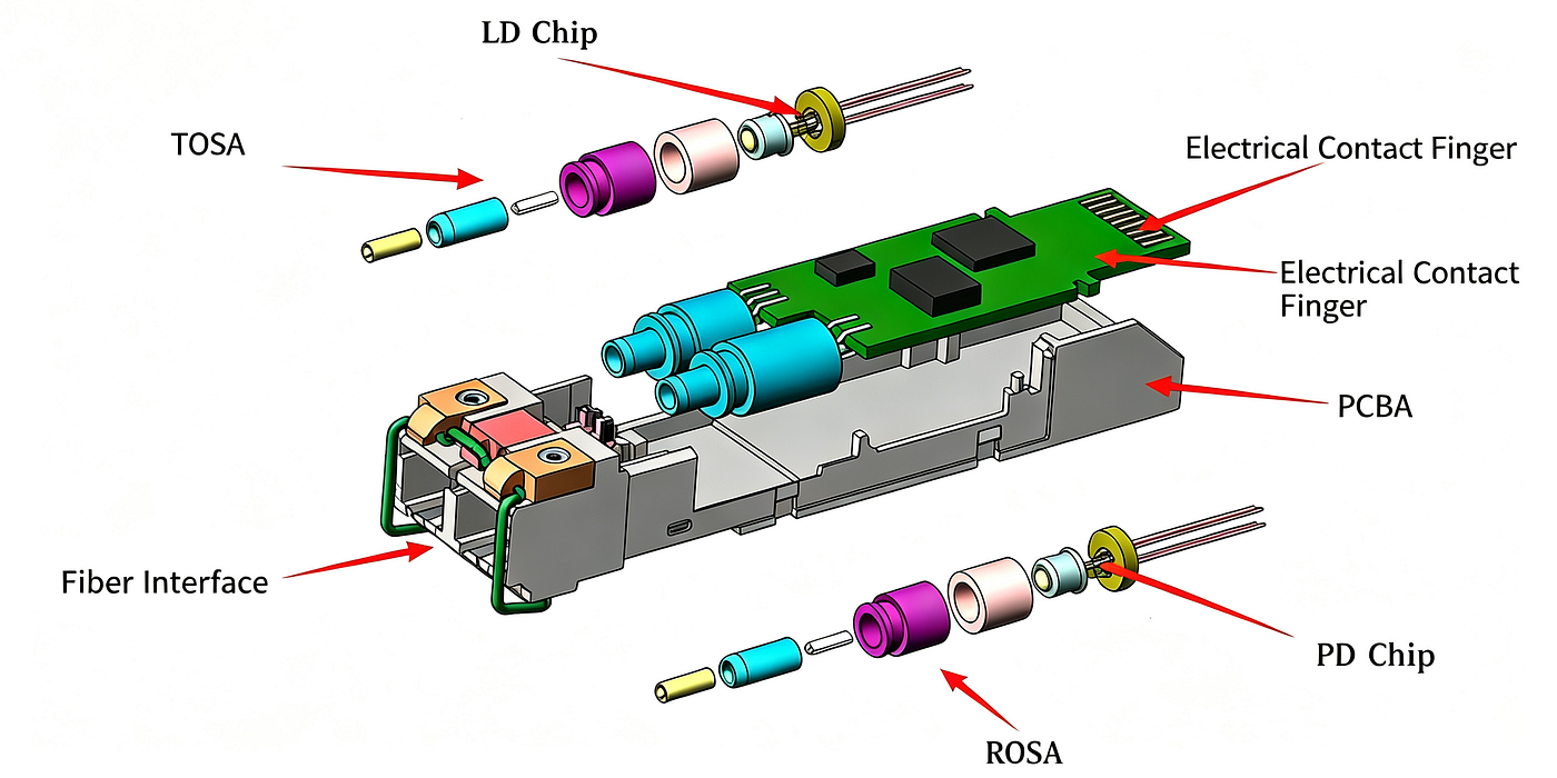
An optical module is the core device of an optical communication network, performing optoelectrical and electro-optical conversion. Inside, laser arrays, photodetectors and fiber arrays sit in tight formation; any positional error at the chip level is magnified by the downstream optical path.
In the optical-module packaging process, die bonding is the first process step that picks the laser chip (or bar) and detector chip from incoming material, places and bonds them onto the substrate or carrier. In process-sequence terms, die bonding is the first forming step that turns a bare die into a “located component”; every subsequent optical path and alignment uses this placement position as its reference, so die-bonding precision is the starting point of the entire packaging chain.
Rate evolution further raises the weight of this gate. Today’s mass-produced 400G/800G modules for AI servers still use conventional pluggable packages, while at 1.6T and beyond CPO co-packaging is adopted and die bonding is completed by high-precision TCB (thermocompression bonding). Market share of high-speed optical modules keeps concentrating toward faster rates, further amplifying the yield requirement on die bonding.
This article focuses on the machine-vision positioning optical scheme for the die-bonding process, analyzing its imaging requirements and how they map to product parameters.
2. Vision Requirements in the Die-Bonding Process
The vision task in die bonding is to image and judge the chip’s position, angle and bonding state before and after pick-and-place, feeding reliable coordinates to the motion mechanism.
These requirements can be split into two layers: camera sensor and magnification, and telecentricity and multi-camera calibration.
2.1 Camera Sensor and Magnification Configuration
The equipment configuration gives a concrete set of indicators: a 12-megapixel 1.1-inch camera paired with a 0.8/1.5/2/4× high-resolution telecentric lens with working distance ≥150 mm, four sets per machine.
The reason for the 1.1-inch large sensor: 12 million pixels spread over the 1.1-inch area give larger pixels and better signal-to-noise ratio. Combined with the high-resolution telecentric lens, the same field of view can cover the whole substrate layout while still resolving chip-edge details, with no need to choose between field of view and resolution. The configuration also gives 0.8/1.5/2/4× magnification options for different station needs: low magnification covers the full substrate and incoming-material layout, high magnification resolves chip edges and bond pads; the die bonder switches magnification before and after pick-and-place, bridging coarse positioning to fine inspection.
2.2 Telecentricity and Multi-Camera Consistent Calibration
The requirement of WD ≥150 mm and telecentricity comes from two constraints: the physical layout of the die bonder and imaging stability. The die head and robotic arm move back and forth in front of the lens; a long working distance leaves safe operating space and avoids mechanical interference. Telecentricity keeps the chip from distorting or introducing perspective effects across the depth range and height variation, so pick-and-place coordinates remain stable and reproducible.
A telecentric lens has parallel chief rays on the object side and constant magnification regardless of object distance, stabilizing sub-pixel positioning at chip pads and bond edges and avoiding the coordinate bias from the “near-large, far-small” effect of conventional lenses — this matters particularly for the downstream chain of wire bonding and inspection.
Four camera sets per machine are needed because die bonders must simultaneously verify the incoming-material, bonding and inspection positions. Once the four cameras are consistently calibrated they can run positioning and verification in parallel, shortening per-die cycle time and reducing the whole-line stoppage from a single-point failure. The four cameras must be consistently calibrated into a unified coordinate system; any assembly deviation or thermal drift in one camera is exposed by multi-view cross-checking, guaranteeing overall positioning consistency — this is the real requirement that the multi-camera layout places on lens calibration consistency.
3. Machine-Vision Optical Solution for the Die-Bonding Process
For this precision gate, COOLENS has developed a vision-positioning optical solution for optical-module die bonders. Built around this lens family, the vision scheme stably supports 3–5 μm positioning precision. The lenses adapt to 1.1-inch cameras and offer 0.8–4× magnification with WD150–180 mm.
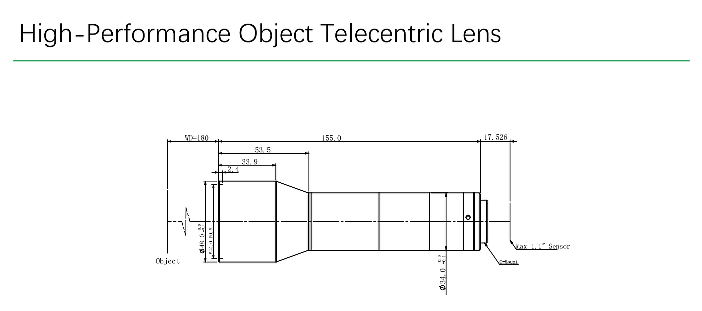
Illustrated model (Note: 0.8× magnification)
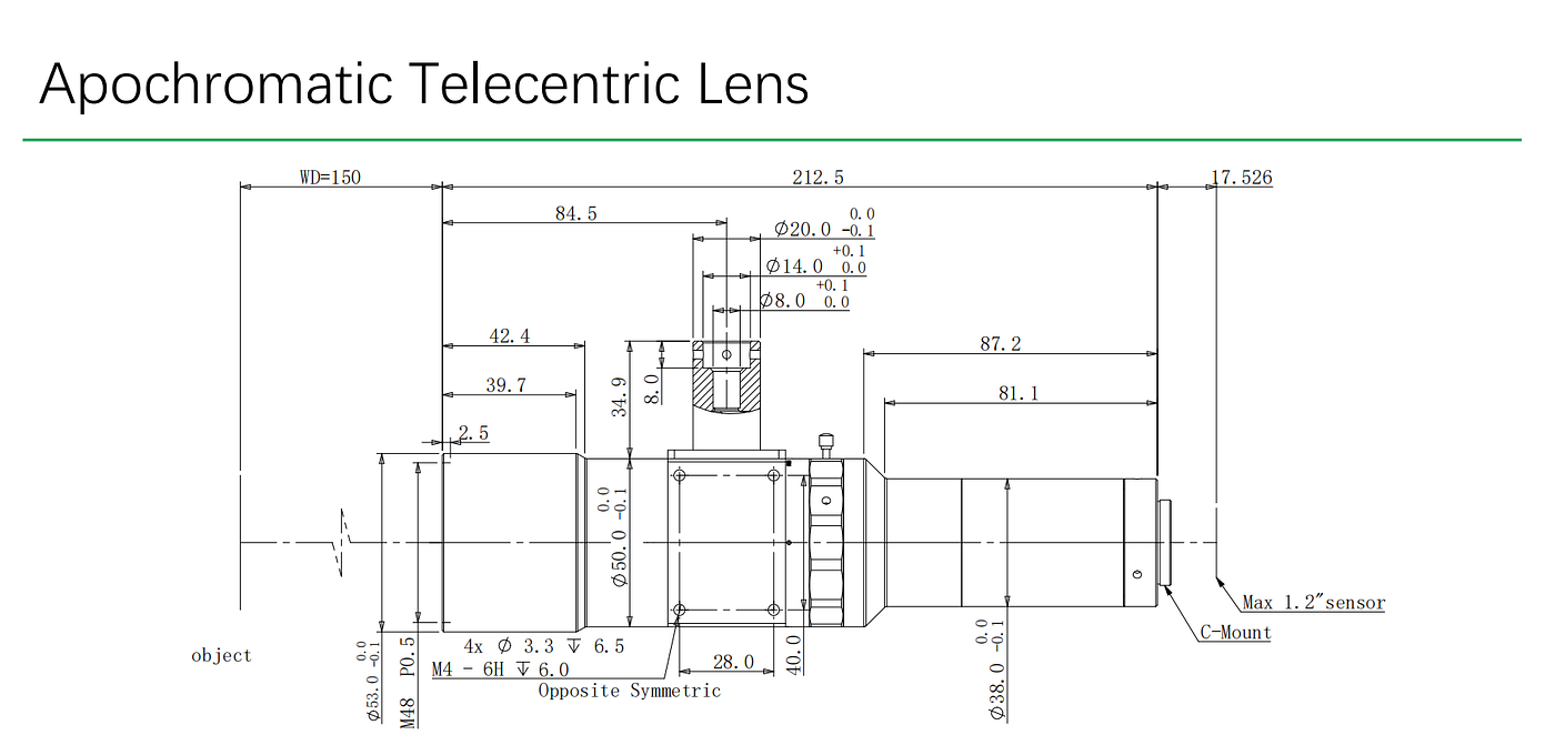
Illustrated model (Note: 2× magnification)
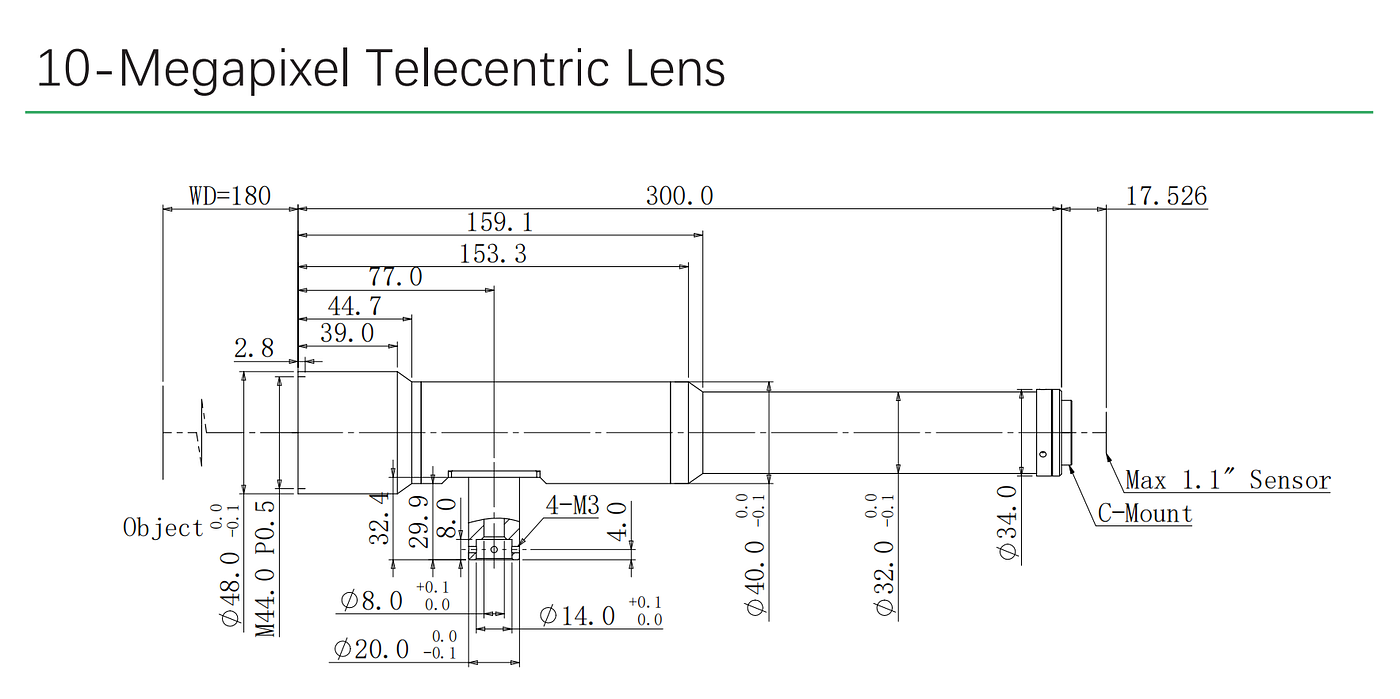
Illustrated model (Note: 4× magnification)
Mapping to the requirements point by point: the 0.8–4× range spans the field-of-view needs from viewing the whole substrate to resolving the chip; WD150–180 mm satisfies the equipment’s ≥150 mm space requirement, leaving ample operating space for fixtures and motion mechanisms; the high-resolution optical design supports the 12 MP imaging need and guarantees credible coordinate judgment.
In a four-camera synchronous layout, the object-side telecentric design provides good telecentric consistency, reducing positioning jumps caused by substrate-height variation and raising multi-camera calibration consistency for more stable multi-view verification. As 1.6T modules move into volume production and TCB processes spread, die bonding demands tighter positioning accuracy and synchronization with machine cycle time; this lens matched to 1.1-inch sensors and WD150–180 mm aligns with that evolution.
This solution focuses on visual support for conventional optical-module die bonding, and under the high-precision TCB trend continues to serve the die-bonding process’s requirements for vision positioning accuracy and stability.
4. Conclusion
Die bonding is the first step from chip to optical path, and the first place where yield is “charged to the books.” As rates head toward 1.6T and packaging toward CPO, die bonding evolves toward high-precision TCB; machine vision positioning is no longer just an image-capture module inside the equipment, but the foundational capability that holds line yield.
COOLENS has translated the three requirements — large-sensor matching, long working distance and telecentric consistency — into concrete optical parameters: 1.1-inch camera compatibility, 0.8–4× magnification and WD150–180 mm, providing a deployable machine-vision optical solution for the die-bonding precision gate.
Frequently Asked Questions (FAQs)
Q: What is die bonding in optical module packaging?
A: Die bonding is the first process step that picks the laser or detector chip from incoming material and places and bonds it onto the substrate or carrier; every later optical alignment uses this placement as its reference.
Q: Why does 1.6T push die-bonding precision harder?
A: 1.6T modules move toward co-packaged optics (CPO) and use high-precision TCB (thermocompression bonding) to complete die bonding; market share also concentrates on faster modules, so any yield loss is amplified.
Q: What is a typical vision configuration?
A: A common configuration is a 12-megapixel 1.1-inch camera with a 0.8/1.5/2/4× telecentric lens and working distance ≥150 mm, four camera sets per machine.
Q: Why does telecentricity matter for die bonding?
A: Telecentricity keeps chief rays parallel on the object side and magnification constant regardless of object distance, stabilizing sub-pixel positioning at chip pads and bond edges and avoiding the coordinate bias from perspective in conventional lenses.
Q: What positioning accuracy can the vision solution support?
A: With the COOLENS lens configuration, the vision solution stably supports 3–5 μm positioning accuracy.
메타데이터
- post_id
- bb59b5bcbe6c
- slug
- machine-vision-positioning-for-optical-module-die-bonding-high-precision-placement-for-bb59b5bcbe6c
- url
- https://medium.com/@coolens2025/machine-vision-positioning-for-optical-module-die-bonding-high-precision-placement-for-bb59b5bcbe6c
- canonical_url
- https://medium.com/@coolens2025/machine-vision-positioning-for-optical-module-die-bonding-high-precision-placement-for-bb59b5bcbe6c
- author_url
- https://medium.com/@coolens2025
- status
- ok
- fetched_at
- 2026-08-17 02:16:25