Active Filters vs Passive Filters in Electronics
In this article, we cover the variation of filters based on how the filter system powers up. Two types available: Active and Passive…
Active Filters vs Passive Filters in Electronics
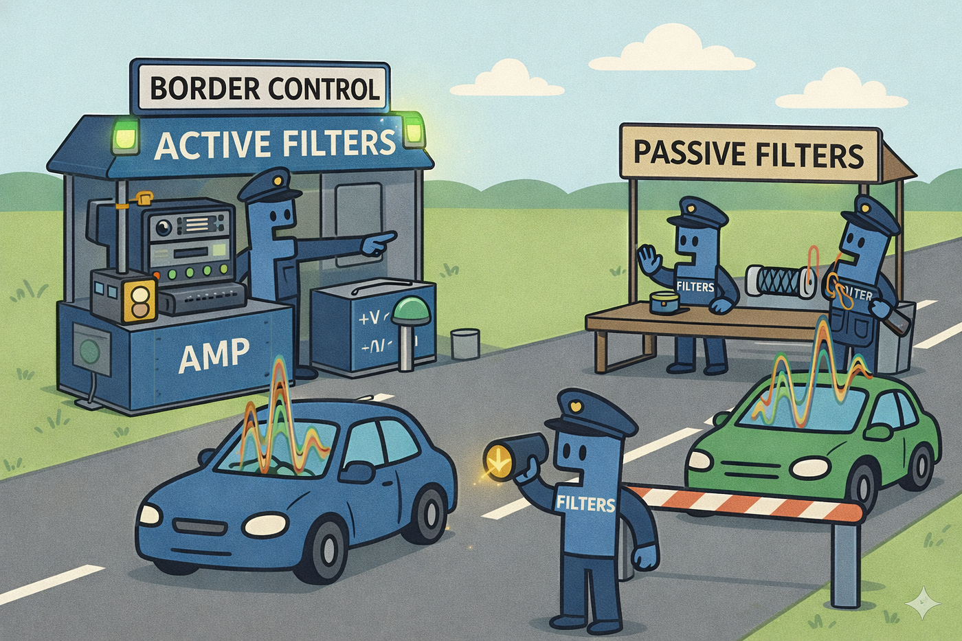
In this article, we cover the variation of filters based on how the filter system powers up. Mainly, two methods are available: active filters and passive filters.
This is part two of the Filter Design series. Therefore, before continuing with the article, please refer to the first part of the series. You can refer to it using the following link.
Let’s continue the article.
How to classify these filters?
This classification of the filters mainly forces how the filters are powered up. These are primarily two methods available: Active filter and Passive filter.
Active Filter: To operate the filter, an external power source is required. That’s why this type is named the active filter. An op-amp (operational amplifier) or a transistor is the key component here. Also, resistors and capacitors are used to create the filter. But, no need to place inductors. It brings more advantages than the passive filter type in some scenarios.
Passive Filter: Here, the external power sources are not required to power up the system. It absorbs some portion of the input signal power to operate. That’s why this is called passive filters. Only the capacitors, resisters and inductors are needed to create the filter. It creates a simple and less complicated design than the active filters.
Let’s find out more about these two.
Active Filters
As mentioned above, active filters work with op-amps and transistors and need an external power source. These create unique characteristics, advatantages and disadvantages. Let’s discuss the main points of them.
This is an example of an active filter used for low-pass filtering.

Active low pass filter circuit | Source learningaboutelectronics.com
Key characteristics
These are the key characteristics of an active filter.
Can amplify the signal: Using the external power source, the input signal can be amplified. So, the gain is more than 1.
High input impedance: Because of the op-amp and transistor working principles, these draw negligible current (nanoamps or picoamps) from the signal source. It shows as a very high resistance or High input impedance.
Low output impedance: The output stage of the op-amp and the transistor is configured in a push-pull arrangement. This allows for a stable voltage while being able to source or sink significant current. This makes the output behave like an ideal voltage source with Low output impedance.
Better control of cutoff frequency and Quality factor (Q): Due to the absence of inductors and the resistors being the ones that are controlled, all the parameters become sharper and more controllable.
Operations limited by the op-amp bandwidth and power range: The op-amps typically work from 0 Hz up to 10 MHz. Beyond that level, the op-amps can’t work. Also, high-power signals saturate the op-amp or, in the worst cases, destroy the op-amp.
Therefore, selecting the type needs to be done carefully.
Advantages
There are several pro things about active filters. These are some of them.
Gain and filtering can be performed simultaneously: The way that implements the circuit, gain and filtering can be done easily. This is simply the overall circuit complexity.
No inductors needed: Here, the op-amp simulates the process of inductance. It makes the circuit smaller, lighter and lowers the cost in lower frequency ranges.
Excellent Isolation (Buffering): Due to the active filters having high input impedance and low output impedance, they act as a buffer. It separates the input signal side and the output signal side.
These create an active filter with greater choice for filtering the signals.
Disadvantages
Same as every other thing, Active filters have their own disadvantages. Before used in a circuit, we need to have a better understanding of these points. These are the key points.
Power Supply is mandatory: Unlike passive filters, active filters cannot function without an external DC power supply.
Can not work at high frequencies: Every Op-Amp has a Gain-Bandwidth Product (GBW). As the frequency increases, the Op-Amp’s ability to provide gain drops. Because of it, above a certain frequency level, active filters can not work. Typically, active filters start to struggle at the 1 MHz to 10 MHz frequency range.
Limited Power Handling capabilities: The active filters are designed only to work at the signal-handling level. Therefore, when we are going to handle high-power situations, some distortions can appear. In the worst case, the system can be burned.
Noise and Distortion: Active components (transistors and Op-Amps) naturally generate a small amount of electronic “hiss” and thermal noise. In extremely high-fidelity audio or scientific measurement, a high-quality passive filter might be preferred because it is “quieter.”
Therefore, we need to understand the filter requirement completely before selecting the filter. If the cons points are negligible, the project can proceed with active filters.
Use cases of Active Filters
The active filters are more ideal when signal gain is needed, compact designs, or when precise filter characteristics are required. These are some use cases of active filters.
- Audio processing
- Medical sensors (like ECG and EEG)
- Signal conditioning
- low-frequency communication
- Anti-aliasing filters (before ADC).
Let’s move to the other filter type that we discussed here.
Passive Filters
On the other hand, passive filters work with inductors, capacitors and resistors only. Therefore, no need to supply an external power supply. Same as before, this configuration generates unique characteristics, advantages and disadvantages. Let’s go through one by one.
This is an example of a passive low-pass filter.

Passive low pass filter circuit | Source: wikipedia.org
Key characteristics
These are the key characteristics of a passive filter.
No amplification: Because of the absence of an external power source, extra power can not be provided to the signal by the filter itself. Also, to operate the filter, the requirements of the filter are also provided by the input signal. Therefore, the gain of the filter is always less than 1.
No Power Supply Required: Since they don’t use transistors or op-amps, they don’t need a battery or external power source.
Simple and reliable: Unlike the active filters, only a few components are needed to create the filter. Because of it, the system becomes simple and reliable.
Frequency response depends on component tolerances: The parameters of the filter are interdependent on the components. Therefore, the frequency response depends on the component tolerances.
Loading effects matter: In passive filters, there is no buffering mechanism, unlike in active filters. Therefore, the filter’s behaviour changes depending on what is plugged into its output. If the load changes, the cutoff frequency might shift unexpectedly.
So, if the above characteristics match the application, the passive filter can be used in the project.
Advantages
When we select the passive filters for the operation, we can achieve some advantages that the active filters cannot provide. These are the main points of them.
No Power Supply Required: As explained earlier, because of the absence of the op-amps or transistors, passive filters no needed extrernal power source.
Best for the High Frequency domain: Passive filters can operate effectively into the Gigahertz (GHz) range. As you learn above, active filters can not operate in this domain because op-amps can not handle the bandwidth.
Higher power handling capability: Unlike op-amps, capacitors and inductors can handle very high voltages and currents. Because of it, passive filters can manage the high-power scenarios without any issues.
Simplicity and Reliability: With fewer parts and no active silicon to fail, passive filters are incredibly robust and have a longer operational lifespan in harsh environments.
Low Electronic Noise: Because there are no transistors or op-amps, passive filters do not generate the “hiss” or thermal noise inherent in active circuits.
Therefore, Passive filters are a great choice for filtering. In some applications, this becomes the only option for the process. But there are some drawbacks that come with the passive filters.
Disadvantages
As mentioned earlier, passive filters have their own disadvantages. There are the main drawbacks that need to be considered.
Signal Attenuation: Passive filters do not use any external power sources to operate. Because of it, the power to do the filtering works gets form the input signal itself. Therefore, the output will always be weaker than the input.
Bulky at Low Frequencies: When we use passive filters in low-frequency division, needs to use very large inductors. These can be heavy, expensive, and take up significant space on a circuit board.
Loading Effects: The passive filter’s behaviour changes depending on what is plugged into its output. If the “load” changes, the cutoff frequency might shift unexpectedly.
Lack of Isolation: There is no buffering method between the input and the output. If you try to stack (cascade) two passive filters to make a sharper cutoff, they will interfere with each other, making the math very difficult.
Component Tolerances matter: Since the passive filters depend on the inductors and capacitors, the overall tolerance of the filter heavily depends on the component Tolerances. If we need to design a passive filter with a perfectly precise cutoff frequency, the cost becomes expensive.
Therefore, we need to understand the requirements of the filter before selecting the filter for the project.
Use cases of Passive Filters
As you learn from the above parts, the passive filters are ideal for high-power and high-frequency applications. These are some of them.
- Power supply filtering — Ripple filtering, EMI suppression, Power factor correction,
- EMI/EMC noise filtering — prevent interference with nearby systems
- RF and Communication filtering — Antenna tuning, Harmonic suppression, Band selection
- Analog Audio tone shaping — loudspeaker crossovers, Treble and bass adjustment
- Signal conditioning — Remove DC offset, Smoothing sensor output
- Transient suppression — Surge and noise filtering, Static discharge protection
Summary
Now you know where and why these active and passive filters are designed to work. The following figure shows the whole article in a simple and compact form.

As a summary of the filter selection,
If using RF, EMI, Power supply and High-power audio applications, always stick with Passive filters.
If using Analog audio, lower frequency and sensor signal applications, always use Active filters.
The next stop is the topologies for filter designing. Stay tune!
메타데이터
- post_id
- bb706c72ed35
- slug
- active-filters-vs-passive-filters-in-electronics-bb706c72ed35
- url
- https://medium.com/@kavindumakaranda/active-filters-vs-passive-filters-in-electronics-bb706c72ed35
- canonical_url
- https://medium.com/@kavindumakaranda/active-filters-vs-passive-filters-in-electronics-bb706c72ed35
- author_url
- https://medium.com/@kavindumakaranda
- status
- ok
- fetched_at
- 2026-07-09 03:40:04
