Design for Testability: Response Compaction and Signature Analysis
The previous article closed with the decompressor: a network that takes a small number of external inputs and expands them into a much…
Design for Testability: Response Compaction and Signature Analysis
The previous article closed with the decompressor: a network that takes a small number of external inputs and expands them into a much larger number of internal scan chain values. The mathematics were clean. The encoding was deterministic. Given a valid seed, the decompressor reconstructs the required pattern on silicon with certainty.
The output side is less clean. And that asymmetry is not an oversight. It is a deliberate engineering trade-off, accepted because the alternative is worse.
This article covers what happens after capture cycle. That response must travel back to the tester, and the path it takes through the compactor introduces a concept that does not exist on the stimulus side: aliasing. Understanding why compaction is done anyway, and why the risk it introduces is acceptable, is what this article is about.
What Happens After Capture
During a scan test operation, the sequence is: shift in, capture, shift out. The shift-in phase loads test stimulus into the scan cells via the decompressor. The capture phase applies functional clocks and lets the combinational logic evaluate. The shift-out phase reads the resulting state back out of the scan cells toward the tester.
In an uncompressed design with C scan chains, shift-out sends C bits per clock cycle across C dedicated output pins to the tester, where they are compared against expected values stored in tester memory. Every bit is individually observable. Every deviation from expectation is individually flagged.
With compression, the output side mirrors the input side structurally: instead of C output pins, there are W output channels, where W << C. The compactor collects responses from all C chains and folds them into W channels using an XOR-based network. The tester sees only W output values per shift cycle.

The gain in output bandwidth is identical to the input side: the same ratio that reduces stimulus data also reduces response data. Tester memory savings and shift time reductions apply symmetrically to both directions.
But the similarity between decompressor and compactor ends there. On the input side, the encoding is solved before test and baked into the seed vector. Any pattern that cannot be encoded is simply excluded from the compressed test set. There is no ambiguity. On the output side, the compactor cannot exclude anything. Whatever state the scan cells hold after capture must pass through the compactor regardless, and the compactor maps C bits of response to W bits of output. This is a many-to-one mapping, and many-to-one mappings introduce the possibility that two different inputs produce the same output.
That possibility is called aliasing.
What Aliasing Means
Aliasing occurs when the compactor maps a faulty circuit response to the same output signature as the fault-free circuit response.
When a fault is present in the design, capture produces a response vector that differs from the fault-free response in at least one scan cell. Call the fault-free response R_good and the faulty response R_bad. In a fully observed design, R_bad != R_good means the test fails — the tester sees an unexpected bit and flags the device as defective.
Through the compactor, both R_good and R_bad are compressed to W-bit signatures. Call these S_good and S_bad. If the compactor maps them to different signatures, S_bad != S_good, the tester still detects the fault. But if S_bad = S_good — if R_good and R_bad differ in exactly the bits that the compactor XORs together to cancel each other out — then the tester sees no difference. The fault is present. The test passes. The device ships.

In this example, the three bits that changed in the faulty response (positions 0, 1, 2) all fed into the same XOR output, and their combined effect cancelled. The compactor produced the correct signature despite the wrong input.
The Probability Argument
Aliasing sounds catastrophic. If a compactor can miss faults, why use one?
The answer is probability. With a well-designed compactor, the probability of aliasing for any given fault is extremely small, and the probability that a faulty device escapes detection across all test patterns is negligible in practice.
For a single W-bit XOR compactor output driven by C input bits, the probability that a random error pattern produces the same signature as the fault-free pattern is:
For a single-output XOR compactor (W = 1 bit):
  P(alias) = probability that error vector e has even parity
           = 1/2

This is too high. Not useful.
For a W-bit output compactor (W output channels, each driven
by a distinct subset of input chains via XOR):
  P(alias per pattern) = 1 / 2^W
  W = 16:   P = 1 / 65,536      = 0.0015%
  W = 32:   P = 1 / 4,294,967,296  ~ 2.3 x 10^-10
With W = 32 output channels, the probability that any single faulty pattern aliases is roughly 2 in 10 billion. This is small enough to be accepted in production test. The compactor design is the engineering lever that drives aliasing probability to this level.
The key insight is that W must be large enough to make aliasing negligible, but it need not equal C. A 32-bit compactor observing 512 chains provides adequate statistical confidence while achieving a 16x reduction in output bandwidth. The trade-off between output reduction and aliasing risk is explicitly parameterized and controlled.

Multiple-Input Shift Register Compactors
In practice, compaction is not done with a single combinational XOR tree applied once at the end of shift. Instead, the response bits are accumulated cycle by cycle into a structure called a Multiple-Input Shift Register (MISR).
A MISR is a linear feedback shift register with multiple XOR injection points. At each shift cycle, the current state of the MISR is updated based on both its previous state and the new response bits arriving from the internal scan chains. After all shift cycles are complete, the MISR holds a final signature — a W-bit value that is the accumulated result of every response bit from every shift cycle.

The MISR’s signature is a compressed representation of the entire response bitstream, not just the last cycle. This means a single bit error at any point in the shift sequence — in any chain, at any shift cycle — will propagate into the final MISR state and corrupt the signature, as long as aliasing does not occur.

The MISR is superior to a combinational XOR tree for two reasons. First, it spreads each input bit’s influence across multiple output bits over successive cycles through the linear recurrence, which improves the aliasing probability further compared to a single-pass XOR. Second, it requires only W flip-flops and a small number of XOR gates regardless of how many shift cycles are used, so the hardware cost does not grow with test length.
Space Compaction vs Time Compaction
It is useful to separate two dimensions of compaction that the MISR implements simultaneously.
Space compaction refers to reducing the number of output channels at a given instant in time. At each shift cycle, C response bits are folded into W MISR inputs. This is the ratio C/W, and it is what drives output pin count reduction. The compactor implements space compaction through the XOR injection network that maps C chains to W MISR inputs.
Time compaction refers to accumulating response bits across multiple shift cycles into a single signature. The MISR’s recurrence relation means that the final signature reflects every response bit from every cycle, not just the last one. This is time compaction, and it is what allows the tester to observe an entire shift-out sequence through a single W-bit comparison at the end.

This is a compaction benefit that goes beyond what the compression ratio alone accounts for. The MISR eliminates the need to store expected responses for every shift cycle. The entire shift-out sequence is reduced to a single expected signature, which is precomputed by the ATPG tool from the fault-free simulation and stored in the test program.
Signature Analysis and Precomputation
The expected MISR signature for each test pattern is computed before test, during the ATPG flow. The process is:

The entire chain from seed generation to signature verification is deterministic and traceable. Every value the tester needs — the seed to shift in and the signature to compare against — is computed analytically from the netlist simulation during ATPG. Nothing is estimated or approximated. Only the aliasing risk introduces any statistical element, and that risk is bounded by the MISR width W.
X-States: The Practical Threat to Compaction
The aliasing argument above assumes that the fault-free response is clean means every scan cell holds a well-defined 0 or 1 after capture. In real designs, this assumption breaks down.
X-states (unknown values) appear in scan cells for several reasons: uninitialized memory elements that were not reset before test, bus contention on multi-driver nets, three-state or bidirectional buses in test mode, or clock domain crossings that produce metastable values. When an X propagates into a scan cell and that cell’s output feeds into the MISR, the MISR state becomes corrupted regardless of whether a fault is present.
The consequence is that the final signature is unpredictable for any pattern where X-states contribute to the MISR. This means the expected signature cannot be computed during ATPG — because the fault-free response is itself unknown at the X positions — and the test for that pattern becomes unusable.

X-states do not cause aliasing. They cause a different problem: the pattern becomes untestable because no expected signature can be defined. In practice, a design with high X-state density will have a large fraction of ATPG patterns rendered unusable unless X-masking is applied.
X-Masking: Gating X-States Out of the Compactor
X-masking is the technique used to prevent X-states from reaching the MISR. The idea is to add a controllable gate — typically an AND gate or a multiplexer — on each scan chain output before it enters the MISR. When a particular chain is known to contain an X value in a given shift cycle, its contribution to the MISR is gated off to zero, preventing X-propagation.
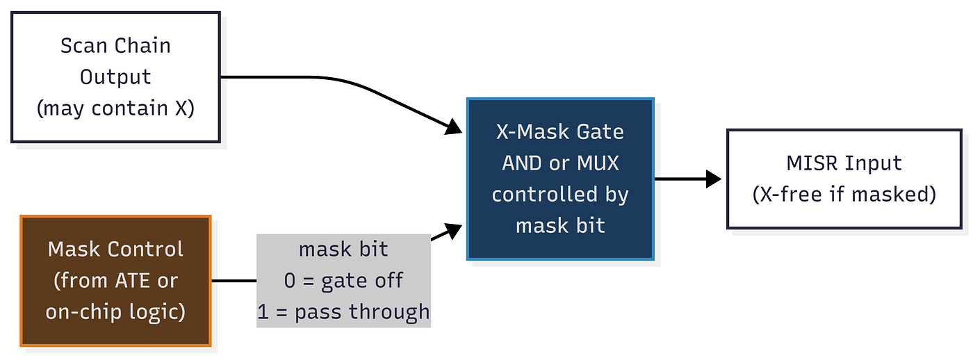
X-masking resolves the corruption problem but introduces a new one: every masked chain is also unobservable for that shift cycle. If a real fault response lands in a masked cell, it is blocked along with the X. Masking too aggressively reduces fault coverage; masking too conservatively leaves X-corruption intact.
The optimal masking strategy minimizes the number of masked cells per pattern while ensuring no X-state reaches the MISR. This is another optimization problem that the ATPG tool solves during pattern generation, and it interacts with the care bit selection on the stimulus side. A scan cell that must be observed (because it carries a fault effect) should not be masked; but if that same cell also receives an X in the same cycle from a different path, the test engineer faces a conflict that may require additional test points, additional patterns, or redesign of the masking architecture.
Closing Remarks
Response compaction through MISR-based signature analysis is the output-side mechanism that completes the scan compression architecture. Several things from this article are worth carrying forward explicitly.
Compaction is a deliberate lossy operation. The MISR maps C bits of response to W bits of signature. Information is destroyed in this process, and that destruction creates the possibility of aliasing. The probability of aliasing is bounded by 1/2^W, and for W >= 32, this probability is negligible in practice. The test engineer accepts this risk because the alternative — observing all C output bits per shift cycle — is either physically impossible (not enough output pins) or economically unjustifiable (tester memory and comparison cost).
The MISR implements both space compaction (folding C chains to W inputs) and time compaction (accumulating all shift cycles into a single final signature). These two together give a compaction factor of C * L / W, which dwarfs the space-only compression ratio by several orders of magnitude in typical designs.
X-states are the practical threat to compaction, not aliasing. An aliased fault has a negligible probability. An unmasked X-state corrupts the MISR deterministically and makes the pattern entirely unusable. X-masking resolves this but at the cost of reduced observability, and the trade-off between masking coverage and X-suppression is a non-trivial design problem in any real flow.
The next article will examine how the decompressor and compactor are combined with the ATPG engine in an end-to-end industrial compression flow, and how the compression ratio, chain count, and masking strategy are co-optimized as a system.
This article is part of an ongoing series on Design for Testability. Previous entries cover fault modeling, ATPG, scan architectures, scan implementation, chain balancing, physical-aware stitching, why compression is mandatory, and linear decompression. The full series is on my Medium profile.
Further Reading:
- Siemens EDA — MISR-Based Signature Analysis in Tessent
- Synopsys — DFTMAX Response Compaction and X-Masking
- IEEE Xplore — X-Compact: An Efficient Response Compaction Technique
- Cadence Modus DFT — Compactor Architecture Overview
Connect with Me:
- GitHub: ranaumarnadeem
- Medium: @ranaumarnadeem
- LinkedIn: Rana Umar Nadeem
VLSI #ASICDesign #LogicSynthesis #ClockGating #LowPowerDesign #RTLDesign #DigitalDesign #DFT #BackendDesign #EDA #Cadence#Genus #Sky130 #RTLtoGDSII #SemiconductorEngineering #PowerOptimization #TechBlog #PREMAPPING #LEC #COP #SOACP #distance #controllibility #modus #scan_chains
메타데이터
- post_id
- bc43fbcf3dfd
- slug
- design-for-testability-response-compaction-and-signature-analysis-bc43fbcf3dfd
- url
- https://medium.com/@ranaumarnadeem/design-for-testability-response-compaction-and-signature-analysis-bc43fbcf3dfd
- canonical_url
- https://medium.com/@ranaumarnadeem/design-for-testability-response-compaction-and-signature-analysis-bc43fbcf3dfd
- author_url
- https://medium.com/@ranaumarnadeem
- status
- ok
- fetched_at
- 2026-06-25 07:00:49