Use a MAX17043 battery voltage meter with an ESP32-H2 Super Mini Development Board and get the…
This tutorial is part of a series of articles about the small ESP32-H2 Super Mini (“SM”) development board. I will explain how to control…
Use a MAX17043 battery voltage meter with an ESP32-H2 Super Mini Development Board and get the battery voltage of your lithium battery and its remaining capacity
This tutorial is part of a series of articles about the small **ESP32-H2 Super Mini (“SM”) development board. I will explain how to control an external MAX17043 battery voltage meter so that you can use it in your projects. I store all relevant settings and methods in a separate header file** so that I can add them modularly as needed.
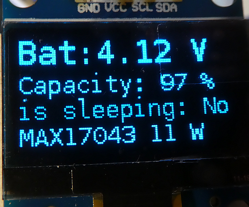
For this tutorial, I have chosen the MAX17043 battery voltage meter, which is designed to reliably measure the battery voltage of a lithium battery and calculate the remaining capacity of the battery.

These modules are available on AliExpress for approximately 3 euros. Please pay attention to the supply voltage (we require 3.3 volts) and the I2C interface. The advantage of the I2C interface is that several different devices can be connected to the two-pin bus, as they have different addresses.

Why do I need a battery voltage meter ?
As long as you’re powering a microprocessor solely via a USB cable, you don’t need to give this issue a second thought. However, as soon as you release your project “into the wild,” the question of power supply becomes entirely relevant. Sure, you’ll almost always find a power outlet in your living space, so using a USB power adapter solves the problem. However, you will inevitably encounter locations where no power outlet is available, such as an unfinished attic or a barn. At this point, you will consider using a battery or rechargeable battery for a power supply.
Since every battery eventually runs out or is depleted, you should replace or recharge it in good time. What good is a burglar alarm, for example, if it doesn’t work when the battery is dead?
Before we delve into the measurement methods, I would like to briefly discuss the special topic of lithium batteries. This type of battery has become the de facto standard recently, as it provides voltages just above the operating voltage of modern microprocessors, for example (3.7 volts). Furthermore, it has sufficient reserves to continue operating without interruption even during peak loads (e.g., when transmitting via Wi-Fi).
However, “where there is light, there is also shadow.” If lithium batteries continue to be used below a certain voltage level, the internal cell structure can be irreparably damaged. Many users are unaware of the impending danger and simply recharge the batteries—what could possibly happen? The damaged structure, completely undetectable from the outside, causes short circuits in the battery, resulting in a sudden discharge of the stored energy—be it through an explosion, smoke, or a raging fire.
None of these situations are desirable, as only a complete immersion of the battery in water can resolve the issue. Therefore, you should always ensure that your batteries never fall below this minimum level.
As protection against undervoltage, but also against overvoltage, overcurrent, and even short circuits, the batteries are equipped either with built-in or later-added protection boards (BMS, Battery Management Systems). They are tiny and cheap, but most people don’t even read the documentation. Here is a typical one:

Specification:
Dimension: 28*3mm (Approx)
Over Charge Release Voltage: 4.275±0.025V
Over Charging Voltage Range: 4.075±0.025V
Over Discharge Voltage Range: 2.5±0.1V
Over Current Detection Current: 2.8±0.3A
But what is the lowest voltage of the lithium battery? Depending on the manufacturer, it lies somewhere between 2.5 volts and 3 volts. This would mean our protection circuit is already at the absolute lowest point at which it disconnects the connection to the battery. Unfortunately, a self-experiment revealed that the small modules only activated below 1.7 volts, which is far too low and raises concerns about permanent damage.
And you must be aware that a voltage level below approximately 3.2 volts will cause a switched-on microprocessor to cease functioning or to fail to wake up from a sleep phase. In such a situation, the device can no longer inform anyone or indicate its precarious condition.
Now that we know what undervoltage is and its consequences, let’s look at our device. We want to know in advance if our device enters a dangerous voltage range, and therefore we are looking for ways to measure an external DC voltage.
Solutions for measuring battery voltage
There are two basic solutions for measuring battery voltage.
- The first and simplest solution is to use a simple voltage divider based on resistors to “divide” the maximum voltage of approximately 4.2 volts (which is the charging voltage of our batteries) down to the maximum input level of an ESP32-H2 input pin (3.3 volts). In the next step, you read the values from the analog-to-digital converter (ADC) and calculate the battery voltage. One minor drawback remains: because the resistors connected in series are directly connected to the battery, a continuous current flows through them, slowly draining the battery. The second drawback: even if I switch off the processor after measuring a low battery level (e.g., putting it into deep sleep mode), the current continues to flow through the resistors.
- In the second option, we use a special module for measuring the battery voltage (**MAX17043) and determine the battery voltage, for example, via the I2C interface. While these modules are more expensive than a voltage divider, the measuring current is significantly lower (1–3 µA)**. Furthermore, we don’t need an additional GPIO pin from our ESP32-H2 Super Mini board, as we already occupy these two contacts with the SHT41 sensor.
In this tutorial I will show you how to operate the MAX17043 on an ESP32-H2 Super Mini board.
Integration of the MAX17043 header file
In the main sketch, you include this header file as follows.
#include "MAX17043_METER.H"The header section defines an entry that can later be referenced in the program to include or omit a part of the program (“preprocessor directives”).
For communication between our ESP32-H2 device and the sensor, I use the **max1704x library** by porrey in version 1.2.9.
The complete header section looks like this:
#ifndef IS_MAX17043_METER
#define IS_MAX17043_METER
#endif
#include "BATTERY_MANAGEMENT.h"
// ------------------------------------------------------------------
// MAX17043 meter
#define MAX17043_I2C_SDA_PIN 5
#define MAX17043_I2C_SCL_PIN 4
#define MAX17043_I2C_ADDRESS 0x36  // from library
#include "MAX1704X.h"  // https://github.com/porrey/max1704x version 1.2.9
//
// Define the MAX17403 fuel gauge. Use MAX17044_mV
// for the MAX17044.
//
MAX1704X max17043 = MAX1704X(MAX17043_mV);
You will notice that I am loading another helper file, the “Battery Management” file. I have separated the battery voltage measurement from the subsequent actions and calculations. The measured values can then be found in the battery management system:
float batteryVoltage = 2.1;
int16_t batteryCapacity = 0;
Setup of the meter
The sensor is wired to an I2C bus, and calling this method will set up the sensor:
void setupMax17043(bool skipWire = false) {...}The parameter “skipWire” is important if you add more than one device on the same I2C bus. To avoid multiple “Wire.begin(…)” commands in this case, you set the parameter to true for all subsequent “setupXXX(true)” calls.

Querying and printing the measured values
Since I put the sensor into sleep mode after a measurement, we wake it up again before taking new measurements:
// wake up the meter
if (isMax17043Sleeping()) {
  setMax17043Wake();
}
For both tasks, I provide methods that are called as follows:
getMax1704Values();
printMax1704Values();
This is a sample output on the Serial Monitor:
ESP32 H2 Super Mini External MAX17043 Battery Voltage Meter and SSD1306 OLED display V01
CPU frequency before setting: 96 MHz
CPU frequency after  setting: 48 MHz
Wire.begin was success
Initializing the MAX17043 instance without an address
MAX1704 set address to 36
The MAX17043 Fuel Gauge is set up
The SSD1306 OLED display is set up
ADC: 3375 Voltage: 4.22 V Remain Capacity: 99 %
Address: 0x36, Version: 3, compensation 0x97
isSleeping No alert active: No
ADC: 3375 Voltage: 4.22 V Remain Capacity: 99 %
Address: 0x36, Version: 3, compensation 0x97
isSleeping Yes alert active: No
A note on the battery capacity: The MAX17043 library also includes a calculation of the remaining battery capacity. However, I trust a lookup table designed by Rop Gonggrijp for his “heltec_esp32_lora_v3” library more. All credit for this part, therefore, goes to him.
Behavior of the sensor at different CPU frequencies
When you select a board in Arduino Tools, you define certain parameters, including the processor speed. However, with the ESP32-H2 Dev Module, there is no way (bug?) to adjust the speed via the Arduino IDE interface.
There is a simple reason for lowering the processor speed: a slower-running processor consumes less power and is therefore a valid option for battery-powered devices to increase runtime.
Therefore, I have included a feature in the test program to reduce the processor speed from 96 MHz (default) to the lowest possible speed of 48 MHz. This is done by enabling (uncommenting) this line in the header:
#define TEST_48MHZ_CPU_FREQUENCYThe result is positive; the program works perfectly even with a CPU speed of 48 MHz.
Test program
The test program tests all the functions of the helper file. To ensure the output is displayed in the “Serial Monitor”, you must enable the parameter “USB CDC on boot enabled” during compilation and upload.
If you want to see the measured values even without the Serial Monitor, I recommend connecting an OLED to the ESP32-H2 (tutorial), and there is an extended version of the MAX17043 sketch in the repository for display output.
Source code of the app
You find the complete code of the app in my **GitHub repository**. Since this is a series of articles, all sketches in this series are compiled in one repository. In this repository, you will find zip files with all relevant libraries used in this sketch, in case they are no longer available online.
Back to the overview tutorial “**ESP32-H2 Super Mini — Small form factor, big impact (LoRa, ePaper, environment sensor, and battery powered and monitored)**”
Happy coding !
메타데이터
- post_id
- be9db05756cd
- slug
- use-a-max17043-battery-voltage-meter-with-an-esp32-h2-super-mini-development-board-and-get-the-be9db05756cd
- url
- https://medium.com/@androidcrypto/use-a-max17043-battery-voltage-meter-with-an-esp32-h2-super-mini-development-board-and-get-the-be9db05756cd
- canonical_url
- https://medium.com/@androidcrypto/use-a-max17043-battery-voltage-meter-with-an-esp32-h2-super-mini-development-board-and-get-the-be9db05756cd
- author_url
- https://medium.com/@androidcrypto
- status
- ok
- fetched_at
- 2026-06-11 15:16:29