From Code to Silicon: Different Types of Synthesis and Their Inputs and Outputs.
In the last blog, “ https://medium.com/@anandpp/why-synthesis-in-vlsi-physical-design-98ca46894305”, I explained what synthesis is, its…
From Code to Silicon: Different Types of Synthesis and Their Inputs and Outputs.
In the last blog, “ https://medium.com/@anandpp/why-synthesis-in-vlsi-physical-design-98ca46894305”, I explained what synthesis is, its goals, and why we check only the setup during synthesis. If you haven't read the previous topic, please click the link.
Now let's focus on the in-depth input and output for synthesis. Since we are explaining about Physical-aware synthesis using the Synopsys tool (Fusion compiler), we have some differences between logical-based synthesis and physical-aware synthesis.
So here first question
What are the different types of synthesis, or what is 2-pass synthesis?
Synthesis is classified into 2
- Logical Synthesis
- Physical aware Synthesis
Logical synthesis: It is a conventional synthesis, where the compiler transforms the RTL to Technology dependend gate-level-Netlist based on the predefined constraints, without considering the physical aspect of the design. Here, the compiler performs optimization purely on Boolean logic optimisation and meets setup timing/area constraints based on these predefined estimates. Since there is no physical data, the tool uses statistical Wire load models (WLMs) to estimate wire delays based on fan-out and area.
Key Characteristics of Logic Synthesis :
Optimization Focus: The compiler prioritises Boolean logic restructuring, gate sizing, and technology mapping to meet timing, power, and area (PPA) targets
Interconnect Modelling: Since physical placement data is unavailable at this stage, the tool relies on Wire Load Models (WLMs). These are statistical models that estimate parasitic capacitance and resistance based solely on gate fan-out and the total area of the design block.
- Limitations:
Because WLMs are based on historical averages rather than actual wire lengths, logical synthesis often suffers from a “correlation gap.” As geometries shrink (especially at 7nm and below), these statistical estimates become less accurate, often leading to timing violations once the design is actually placed and routed.
Physical Aware Synthesis: Physical-Aware Synthesis integrates physical floorplan data directly into the synthesis engine. Unlike logical synthesis, which relies on statistical guesswork, this approach utilizes real-world spatial data to drive optimizations.
By incorporating Design Exchange Format (DEF) files and TLU+ (parasitic RC lookup tables), the tool gains visibility into the physical constraints of the design, including macro locations, power grid footprints, and specific cell placement coordinates based on actual Euclidean distances rather than statistical guesswork, ensuring that the netlist generated is physically routable and timing-accurate and optimizes the design and generate Gate-level Netlist.
Key Advantages:
Accurate Interconnect Modeling: Instead of using Wire Load Models, the engine calculates RC delays based on Euclidean distances (actual Steiner tree estimates). This ensures that the timing reports generated during synthesis closely correlate with the results seen in the later Place and Route (PnR) stages.
Routability-Driven Optimization: Because the tool is aware of congestion and physical boundaries, it avoids creating “logic bottlenecks” that would be impossible to route later, resulting in a significantly more “physically-ready” Gate-Level Netlist.
PPA Predictability: By mimicking the physical design environment through the use of technology files and floorplan data, the Power, Performance, and Area (PPA) metrics are far more realistic, reducing the number of iterations between the Front-End and Back-End teams.
Here, when we look at logical synthesis and physical-aware synthesis, we have an important question.
How do we move beyond statistical Wire Load Models (WLMs) to achieve high-correlation PPA results using DEF and TLU+ files?
To achieve high-correlation results in modern VLSI design, at advanced nodes (7nm and below), the delay contributed by interconnects often outweighs the cell delay, making statistical models like WLMs obsolete.
When we use traditional synthesis, which uses Wire Load Models (WLMs), estimate capacitance and resistance based on a net’s fan-out and the total area of the block. This ignores the actual placement of cells. When we provide the tool with a DEF (Design Exchange Format) file, which contains information such as:
- Macro Placement: Where the memories and IP blocks are located.
- Power Grid (PG) Strategy: Where the supply rails are, which impacts available routing tracks.
- Physical Boundaries: The exact die/floorplan limits. etc..
By knowing where the pins are, the tool calculates Euclidean distances and builds a virtual “Steiner Tree” for each net. Instead of guessing that a net with fan-out 3 or more is “X” microns long, it knows exactly how far those three/more pins are from the driver.
While the DEF provides the “distance,” the TLU+ files provide the “physics.”
- TLU+ (Table Look-Up Plus) files contain the RC (Resistance and Capacitance) coefficients for a specific technology node.
- They account for metal layer thickness, width, and spacing variations defined by the foundry.
When the synthesis engine has both the DEF (distance) and the TLU+ (RC values per micron), it can calculate highly accurate interconnect delays. This eliminates the “correlation gap,” where a design passes timing in synthesis and has a high chance of closing the Timing in PnR as well.
Input for Synthesis
- RTL code
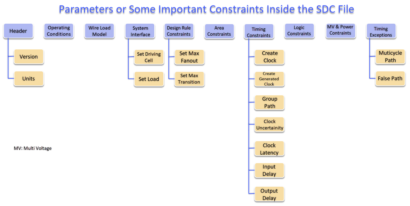
- SDC (Synopsys Design Constraints)
- Tech files (.lib and .lef)
- .DEF (Floorplan information)
- .UPF (low power information)
- TLU+ (RC coefficient)
Output from Synthesis
- Optimized and mapped Gate-level Netlist
- Synthesize SDC
- Synthesize floorplan DEF
- Golden UPF
- Timing/Area/Power reports.
To truly master the synthesis flow, one must understand the data that fuels it. Over the next few posts, I will break down each input requirement one by one. Our first stop: SDC File.
We’ll discuss its structure, its role in defining design intent, and why it is the backbone of any successful synthesis run.
Let’s Connect:
Medium: Anand P P
LinkedIn: Anand PP
메타데이터
- post_id
- c24324fca3a7
- slug
- from-code-to-silicon-different-types-of-synthesis-and-their-inputs-and-outputs-c24324fca3a7
- url
- https://medium.com/@anandpp/from-code-to-silicon-different-types-of-synthesis-and-their-inputs-and-outputs-c24324fca3a7
- canonical_url
- https://medium.com/@anandpp/from-code-to-silicon-different-types-of-synthesis-and-their-inputs-and-outputs-c24324fca3a7
- author_url
- https://medium.com/@anandpp
- status
- ok
- fetched_at
- 2026-08-22 16:15:21