Making an OS from scratch
Building a legacy x86 operating system with a VGA 80x25 display from the ground up
Making an OS from scratch
Building a legacy x86 operating system with a VGA 80x25 display from the ground up
If you’ve ever wondered how operating systems actually work under the hood, you’re not alone. Most of us use operating systems daily without ever thinking about what happens when we press the power button. In this article, I’ll walk you through building a simple operating system from scratch — one that runs on real x86 hardware (or emulators like QEMU), displays text on a classic VGA 80x25 screen, and gives you complete control over the machine.
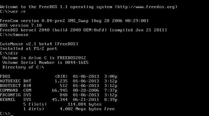
This is reminiscent of how MS-DOS and FreeDOS worked — bare-metal programming where you directly manipulate hardware. Let’s dive in.
The Big Picture
Our OS follows a classic boot process:
- BIOS loads our boot sector (512 bytes) from disk
- Bootloader initializes the system and loads the kernel
- Kernel (written in C) takes over and provides the main functionality
The entire project uses x86 assembly for the low-level boot code, then switches to C for the kernel. But here’s the interesting part — I created a custom preprocessor called rasm (regex assembly) that lets me write assembly at a slightly higher level. We’ll see how this works throughout the article.
This github repo, contains the final result of this whole tutorial.
The Boot Sector
Every x86 system starts by executing code at memory address 0x7C00. This is where our bootloader lives. Let’s start with a simple string-printing function.

The High-Level View (rasm)
Here’s how we write printing in my custom rasm syntax:
print {

   loop {
     al = *bx ; Load character from bx pointer
     if al == 0 end ; Stop if null terminator

     ah = 0xE ; BIOS video interrupt function
     int 0x10 ; Call BIOS

     inc bx ; Next character
     jmp loop
   }

   end {
     popa ; Restore all registers
     ret ; Return to caller
   }

}
This looks almost like pseudocode, right? The *bx means “dereference the pointer in bx” (load the byte at that memory address). The if al == 0 end becomes a compare and conditional jump in real assembly.
The Real Assembly (asm)
Here’s what this actually compiles to:
print:
    pusha                     ; Save all registers

loop:
    mov al, [bx]             ; Load byte at bx
    cmp al, 0                ; Compare to null
    je end                   ; Jump if equal

    mov ah, 0xE              ; BIOS teletype function
    int 0x10                 ; Video interrupt

    inc bx                   ; Advance pointer
    jmp loop                 ; Repeat

end:
    popa                     ; Restore registers
    ret                      ; Return
Notice the pattern? Every “high-level” construct in rasm translates directly to assembly instructions. *bx becomes [bx], al = *bx becomes mov al, [bx], and if al == 0 end becomes cmp al, 0 / je end.
The Bootloader Entry Point
Our main bootloader file ties everything together:
[org 0x7c00]

KERNEL_OFFSET equ 0x1000

*BOOT_DRIVE = dl              ; Save boot drive number
bp = 0x8000                   ; Set up stack
sp = bp

print_hex(bx = *BOOT_DRIVE)   ; Print boot drive in hex
print(bx = MSG_REAL_MODE)     ; Display welcome message

load_kernel()                 ; Load kernel from disk
switch_to_pm()                ; Switch to 32-bit protected mode

jmp $                         ; Hang if something goes wrong
This sets up the stack, prints debug info, loads the kernel into memory at offset 0x1000, and switches to 32-bit protected mode. The jmp $ at the end is an infinite loop — “jump to current position” basically means “hang forever.”
Loading the Kernel from Disk
Reading from disk in 16-bit real mode requires calling BIOS interrupt 0x13. Here’s the rasm version:
disk_read {
    pusha                     ; Save registers
    clr cx                    ; cx = 0 (retry counter)
}

disk_loop {
    inc cx                    ; Increment attempt count

    ah = 0x2                  ; BIOS read sector function
    al = dh                   ; Number of sectors to read
    ch = 0                    ; Cylinder 0
    cl = 0x2                  ; Start from sector 2 (sector 1 is bootloader)
    dh = 0                    ; Head 0
    int 0x13                  ; Call disk BIOS

    if al != dh sectors_error ; Verify all sectors read
}

disk_done {
    popa
    ret
}
The compiled assembly:
disk_read:
    pusha
    xor cx, cx

disk_loop:
    inc cx

    mov ah, 0x2
    mov al, dh
    mov ch, 0
    mov cl, 0x2
    mov dh, 0

    int 0x13

    pop cx
    pop dx

    jc disk_error             ; Jump if carry flag set (error)
    cmp al, dh
    jne sectors_error

disk_done:
    popa
    ret
Switching to 32-Bit Protected Mode
This is where things get interesting. The x86 processor starts in real mode (16-bit, can only access 1MB of memory). To use all our memory and get more powerful instructions, we switch to 32-bit protected mode.
The GDT (Global Descriptor Table)

Flags from Wiki OsDev

Flags from Wiki OsDev
First, we need to set up a GDT — essentially a table that defines memory segments:
gdt_start:
    dd 0x0                    ; Null descriptor
    dd 0x0

; Code segment descriptor
gdt_code:
    dw 0xffff                 ; Limit (4GB)
    dw 0x0                    ; Base (low 16 bits)
    db 0x0                    ; Base (middle 8 bits)
    db 10011010b              ; Flags: present, ring 0, code
    db 11001111b              ; Flags: 4KB granularity, 32-bit
    db 0x0                    ; Base (high 8 bits)

; Data segment descriptor
gdt_data:
    dw 0xffff
    dw 0x0
    db 0x0
    db 10010010b              ; Flags: present, ring 0, data
    db 11001111b
    db 0x0

gdt_end:

gdt_descriptor:
    dw gdt_end - gdt_start - 1 ; GDT size
    dd gdt_start               ; GDT address

CODE_SEG equ gdt_code - gdt_start
DATA_SEG equ gdt_data - gdt_start
The Switch
Now we switch modes:
[bits 16]
switch_to_pm {
    cli                       ; Disable interrupts
    lgdt *gdt_descriptor      ; Load GDT

    eax = cr0                 ; Get control register 0
    eax |= 0x1                ; Set protected mode bit
    cr0 = eax                 ; Enable protected mode

    jmp CODE_SEG:init_pm      ; Far jump to set code segment
}

[bits 32]
init_pm {
    ax = DATA_SEG             ; Set up all segment registers
    ds = ax, ss = ax, es = ax, fs = ax, gs = ax
    begin_pm(ebp = 0x90000, esp = ebp)
}
Compiled:
[bits 16]
switch_to_pm:
    cli
    lgdt [gdt_descriptor]

    mov eax, cr0
    or eax, 0x1
    mov cr0, eax

    jmp CODE_SEG:init_pm

[bits 32]
init_pm:
    mov ax, DATA_SEG
    mov ds, ax
    mov ss, ax
    mov es, ax
    mov fs, ax
    mov gs, ax
    mov ebp, 0x90000
    mov esp, ebp
    call begin_pm
Notice how eax |= 0x1 becomes or eax, 0x1, and multiple assignments like ds = ax, ss = ax, es = ax expand to multiple mov instructions.
The Kernel
Once we’re in 32-bit mode, we can run C code! Here’s where the real fun begins. The kernel_entry.s file is just a tiny stub that calls our C main() function:
[bits 32]
[extern main]
call main
jmp $
Now let’s look at the C kernel. This is where we get VGA graphics working properly.
VGA Memory
The VGA text buffer lives at memory address 0xB8000. Each character takes 2 bytes: the character itself and its attributes (color):
#define VGA_MEMORY 0xB8000
#define MAX_COLS 80
#define MAX_ROWS 25
#define WHITE_ON_BLACK 0x0f
Writing to the Screen
Here’s how we print a character at a specific position:
void print_char(const char c, const uint16_t offset, const uint16_t color) {
    char *vga = (char *)VGA_MEMORY;
    vga[offset] = c;           // Character byte
    vga[offset + 1] = color;   // Attribute byte
}
Each character cell is 2 bytes — one for the ASCII character, one for the color. The color byte is split: lower 4 bits are the foreground color, upper 4 bits are the background.
Getting and Setting the Cursor
To write at the cursor position (or any position), we need to interact with the VGA hardware:
void outb(const uint16_t port, const uint16_t data) {
    __asm__("outb dx, al" : : "d"(port), "a"(data));
}

uint16_t get_cursor() {
    uint16_t position;
    outb(0x3d4, 14);              // VGA cursor high byte
    position = inb(0x3d5) << 8;
    outb(0x3d4, 15);              // VGA cursor low byte
    position += inb(0x3d5);
    return position;
}
The VGA controller has I/O ports at 0x3d4 and 0x3d5. We write command numbers (14 for high byte, 15 for low byte), then read/write the data.
Scrolling
When we reach the bottom of the screen, we need to scroll up:
void memcopy(const char *source, char *dest, const int nbytes) {
    for (size_t i = 0; i < nbytes; ++i)
        dest[i] = source[i];
}

// Inside kernel_print_at():
if (char_pos > MAX_VGA) {
    // Scroll each line up
    for (size_t i = 0; i < MAX_ROWS + 1; i++) {
        const char *source = (char *)VGA_MEMORY + i * MAX_COLS * 2;
        char *destination = (char *)VGA_MEMORY + (i - 1) * MAX_COLS * 2;
        memcopy(source, destination, MAX_COLS * 2);
    }
    offset -= MAX_COLS * 2;
}
This copies each line of video memory one row up, effectively scrolling the screen.
Integer to ASCII
Since we don’t have the C standard library, we need to implement our own conversion:
int int_to_ascii(const int n, char *str, const size_t i) {
    if (n < 10) {
        str[i] = n + '0';
        str[i + 1] = '\0';
        return i;
    }
    str[i] = (n % 10) + '0';
    return int_to_ascii(n / 10, str, i + 1);
}

void itoa(int n, char *str) {
    const size_t len = int_to_ascii(n, str, 0);
    // Reverse the string (recursive approach builds it backwards)
    for (size_t i = 0; i < len; ++i) {
        const char tmp = str[i];
        str[i] = str[len];
        str[len] = tmp;
    }
}
Main Kernel Function
Putting it all together:
int main() {
    clear_screen();                    // Clear to black

    for (size_t i = 0; i < 25; ++i) {  // Print numbers 0-24
        char str[255];
        itoa(i, str);
        kprint_at("C://Home/User/ ", 0, i); // Print at column 0, row i
        kprint_at(str, 16, i);
    }

    // Force scrolling!
    kprint_at("This text forces scrolling. Row 0 will disappear. ", 60, 24);
    kprint("And with this text, row 1 disappears too!");
}
Building and Running
The Makefile ties everything together:
C_SOURCES = $(wildcard kernel/*.c)
OBJS = ${C_SOURCES:.c=.o}

CC = gcc
ASM = nasm
LINKER = ld -m elf_i386
QEMU = qemu-system-i386

CFLAGS = -masm=intel -g -m32 -ffreestanding -fno-pic

# $^ prerequisites
# $< first dependency
# $@ target

# first rule runs by default
os-image.bin: boot/bootloader.bin kernel.bin
 cat $^ > $@

run: os-image.bin
 ${QEMU} $<

kernel.bin: boot/kernel_entry.o ${OBJS}
 # kernel main at 0x1000 written on the linker.ld file
 ${LINKER} -o $@ -T linker.ld $^ --oformat binary

%.o: %.c
 ${CC} ${CFLAGS} -c $^ -o $@

%.o: %.asm
 ${ASM} $^ -f elf -l $<.lst -o $@ || (cat $<.lst | rg error -B 5; exit 1)

%.bin: %.asm
 ${ASM} $^ -f bin -l $<.lst -o $@ || (cat $<.lst | rg error -B 5; exit 1)

run: os-image.bin
    qemu-system-i386 $<
The bootloader compiles to a 512-byte binary (the boot sector), and the kernel compiles to a flat binary. We concatenate them together to get our OS image.
The linker file is pretty simple, notice the 0x1000 as the position of the kernel in memory:
ENTRY(main)
SECTIONS
{
    . = 0x1000;
    .text : { *(.text) }
    .rodata : { *(.rodata*) }
    .data : { *(.data) }
    .bss  : { *(.bss) }
}
Run it with:
make runAnd you’ll see rows 0–24 filled with numbers, then watch them scroll as more text is printed — exactly like the old DOS days!

Conclusion
We’ve built a complete, bootable operating system from scratch:
- Bootloader (assembly): Sets up the system, loads kernel from disk
- GDT & Mode Switch: Transitions from 16-bit real mode to 32-bit protected mode
- Kernel: Full VGA text output with cursor management and scrolling
The rasm preprocessor demonstrates how high-level constructs map to low-level assembly — every line of “fancy” syntax becomes straightforward x86 instructions. This is what compilers do, just at a smaller scale.
This OS gives you a taste of what it was like to write MS-DOS or FreeDOS. From here, you could add:
- Keyboard input
- File system support
- Memory management
- Interrupts and timers
The journey to understanding operating systems starts with a single boot sector. Happy hacking!
References
메타데이터
- post_id
- c8755be9f4cc
- slug
- making-an-os-from-scratch-c8755be9f4cc
- url
- https://medium.com/@ricarditomontserrat/making-an-os-from-scratch-c8755be9f4cc
- canonical_url
- https://medium.com/@ricarditomontserrat/making-an-os-from-scratch-c8755be9f4cc
- author_url
- https://medium.com/@ricarditomontserrat
- status
- ok
- fetched_at
- 2026-07-12 01:29:19