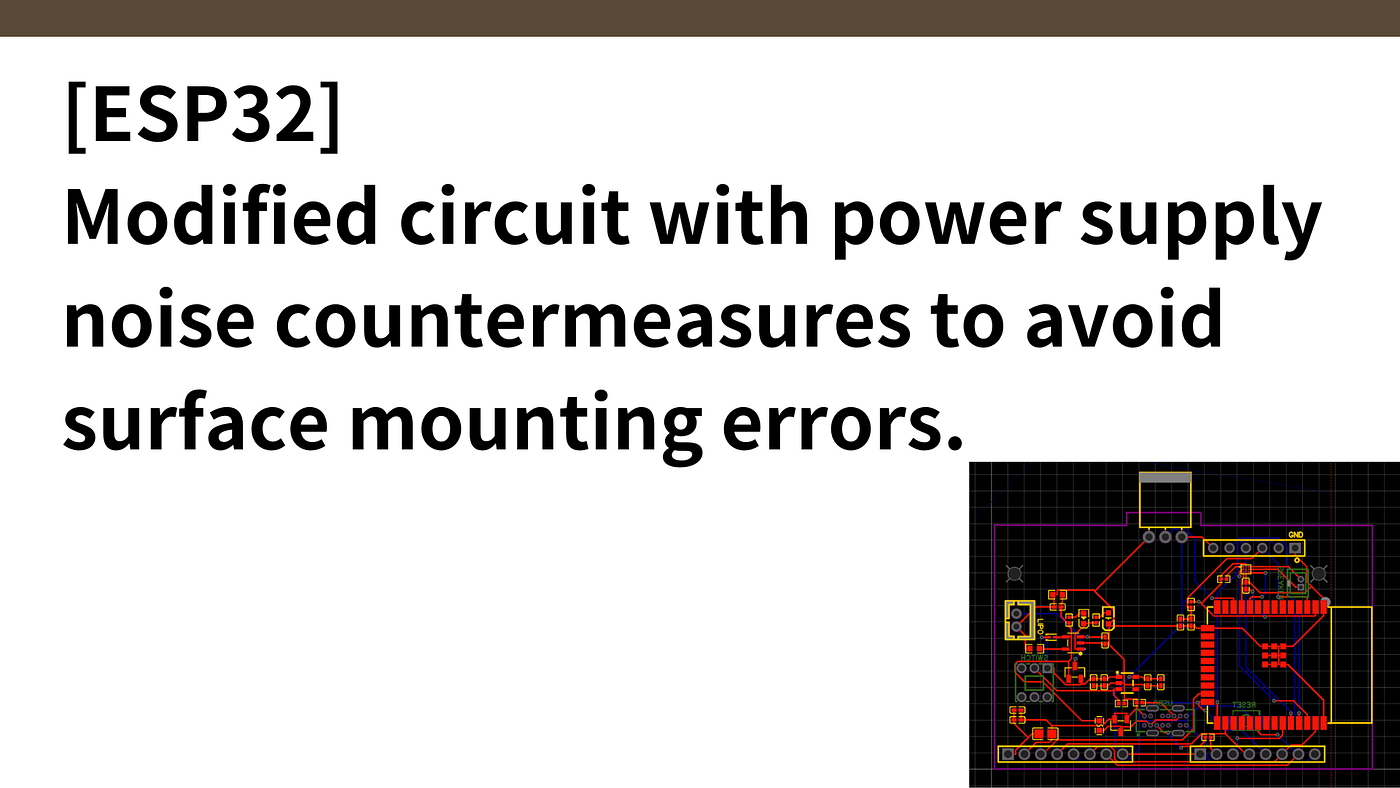
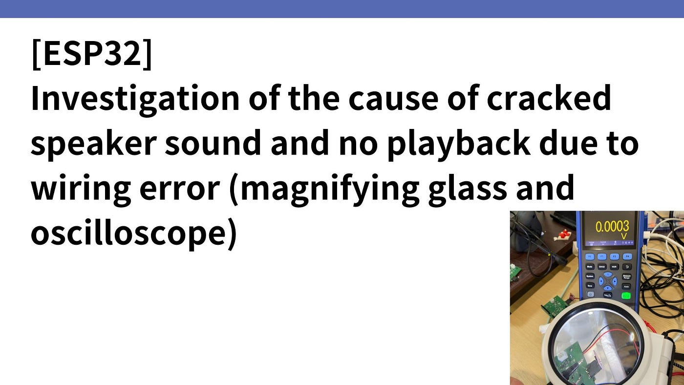
[ESP32 custom board] Result of investigating the cause of board defects by measuring voltage with…
Measuring the voltage of wiring: Since the wiring on the board is often covered with resist (insulation layer),
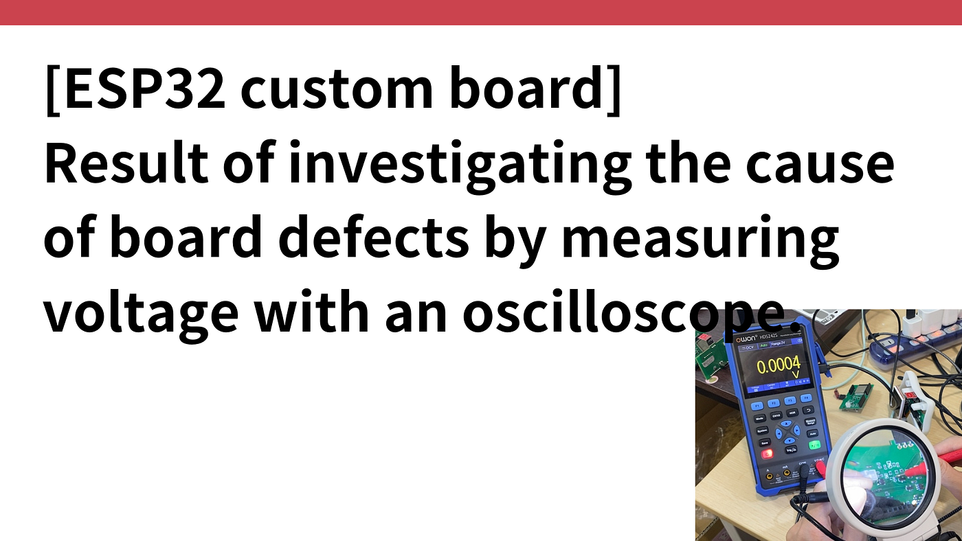
[ESP32 custom board] Result of investigating the cause of board defects by measuring voltage with an oscilloscope.
Introduction.
Developing “Mia,” a talking cat-shaped robot that speaks various dialects.
In the previous article here, I tried to investigate the cause of the defective board, but gave up in the process, so I tried to continue.
Voltage measurement method for boards (component-to-component and wiring)
When we asked the tech staff at TiB FAB, a demonstration field where prototypes can be built and products prototyped, how to investigate the cause, they told us that there are two ways
- Measuring the voltage between components: Measure the voltage by placing the tip of the oscilloscope probe on the soldered component land area.
(2) Measuring the voltage of wiring: Since the wiring on the board is often covered with resist (insulation layer), voltage cannot be measured by applying a probe over the wiring as it is. At this time, to avoid damaging the wiring, the cutting edge of the cutter should be level with the board, and then lightly cut horizontally. Then, the probe is placed in contact with the exposed copper foil and the voltage is measured.
First, measure the voltage between components and proceed to investigate the cause.


Identified 6 patterns causing board defects
It took quite a bit of time, but we were able to disassemble 11 defective boards out of the 150 boards we have ordered so far into the following 6 patterns.
Power failure problem
- IC (Fuse) mount defective: 2 pcs.
- Inadequate USB mount: 1 pc.
- Incomplete buck regulator (ME6217) mount: 1 piece
- Sensitivity failure of latching switch: 1 pc.
Problem of not being able to write code
- TXRX error: 1 piece
Causes of no sound or broken sound
- IC (MAX98357A) mounting error: no sound or broken sound: 5 pcs.
Each will be looked at in detail.
Inadequate buck regulator (ME6217) mount
The 5V power supply from USB is stepped down to 3.3V with a step-down regulator to drive the ESP32. Of the ME6217 components in the circuit diagram below, the difference between pin 3 and pin 1 (input voltage) must be 5V and the difference between pin 3 and pin 5 (output voltage) must be 3.3V.
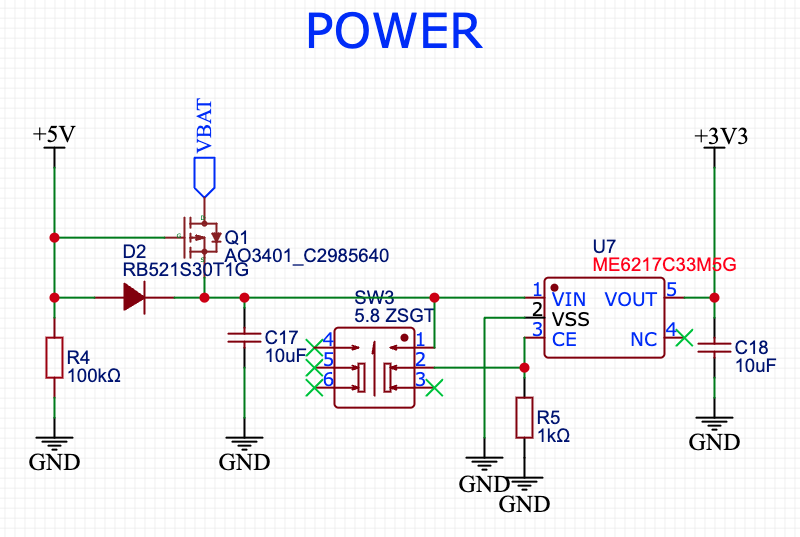

However, when actually measuring, the input voltage is correct at 5V, but the output voltage is 0V instead of 3.3V. This is either because the ME6217 component itself is broken or the ME6217 is surface mounted.
As for this one, I actually inquired about it at the JLCPCB’s Quality Complaint.


IC (Fuse) mount inadequate
The fuse, which is used for the purpose of preventing equipment from becoming dangerous due to overcurrents caused by abnormal conditions in electrical circuits (e.g., short circuits and overloads), must have a voltage of 5 V back and forth on the circuit.


However, when I actually measured it, I found that it was 0V instead of 5V on one of the fuse lands. This is due to the mounting of the fuse.

USB mount defective
The power supply from USB is 5V,..
Read More At
메타데이터
- post_id
- ce29d7cd8d4d
- slug
- esp32-custom-board-result-of-investigating-the-cause-of-board-defects-by-measuring-voltage-with-ce29d7cd8d4d
- url
- https://medium.com/@kazutaka.yoshinaga/esp32-custom-board-result-of-investigating-the-cause-of-board-defects-by-measuring-voltage-with-ce29d7cd8d4d
- canonical_url
- https://medium.com/@kazutaka.yoshinaga/esp32-custom-board-result-of-investigating-the-cause-of-board-defects-by-measuring-voltage-with-ce29d7cd8d4d
- author_url
- https://medium.com/@kazutaka.yoshinaga
- status
- ok
- fetched_at
- 2026-07-22 18:30:54