Ray Tracing From Scratch: BRDFs, Object Lights & Path Tracing
The current ray tracer does not support indirect lighting from non-emissive objects. In order to provide that, the method called path…
Ray Tracing From Scratch: BRDFs, Object Lights & Path Tracing
The current ray tracing does not support indirect lighting from non-emissive objects. In order to provide that, the method called path tracing will be implemented in that blog post. Moreover, object lights as mesh or sphere lights and alternative shading operations called as BRDFs will be added.
BRDF
Bidirectional reflectance distribution functions simulates the surface reflectance according to the incoming and outgoing light rays for each direction. They can be thought as generalizations of the current shading functions. By changing BRDF functions, different shading models can be simulated. BRDFs can be used as the f function in the rendering equation:
![Rendering equation. Retrieved from [1].](https://miro.medium.com/v2/resize:fit:793/1*oVWkDI3EH6ge1IbDiJOyFA.png)
Rendering equation. Retrieved from [1].
Blinn-Phong BRDF
This BRDF represents the current shading model in the implementation. It uses a vector called as half vector calculated by adding light and camera vectors. Then, the angle between half vector and normal, αh, is used as follows:
![Blinn-Phong BRDF calculations. Retrieved from [1].](https://miro.medium.com/v2/resize:fit:727/1*IMyiG-dYdGz12UaHq0TAig.png)
Blinn-Phong BRDF calculations. Retrieved from [1].

Blinn-Phong BRDF output.
Modified Blinn-Phong BRDF
This BRDF is same as the above BRDF except removed cos term in the denominator:
![Modified Blinn-Phong BRDF calculations. Retrieved from [1].](https://miro.medium.com/v2/resize:fit:705/1*ZxcvuorU3rZzY5AF8vwpQA.png)
Modified Blinn-Phong BRDF calculations. Retrieved from [1].

Modified Blinn-Phong BRDF output
Normalized Modified Blinn-Phong BRDF
Normalization provides energy conservation property for BRDFs. Using rendering equation, the energy conservation property can be defined as:
![Energy conservation property. Retrieved from [1].](https://miro.medium.com/v2/resize:fit:607/1*UoLmqQfSLPXlzqs6_9jC_Q.png)
Energy conservation property. Retrieved from [1].

Normalized Modified Blinn-Phong BRDF output
The normalized version of the modified Blinn-Phong BRDF is:
![Normalized Modified Blinn-Phong BRDF calculations. Retrieved from [1].](https://miro.medium.com/v2/resize:fit:752/1*bZAMyMcr2Y783-lglyPB5w.png)
Normalized Modified Blinn-Phong BRDF calculations. Retrieved from [1].
Phong BRDF
The perfect reflection of the of the light ray across the surface normal can be calculated as follows:
![Reflection figure. Retrieved from [2].](https://miro.medium.com/v2/resize:fit:1140/0*jMaqgZv-2d_D-6p-.png)
Reflection figure. Retrieved from [2].
![Reflection calculation. Retrieved from [2].](https://miro.medium.com/v2/resize:fit:200/1*hT-ypxVo4o1-mYix2jBlhg.png)
Reflection calculation. Retrieved from [2].
Then, the angle between the reflected ray and the camera ray, αr, is used as follows:
![Phong BRDF calculations. Retrieved from [1].](https://miro.medium.com/v2/resize:fit:640/1*TX4KjEDj7w2T4pLqzGqxDg.png)
Phong BRDF calculations. Retrieved from [1].

Phong BRDF output.
Modified Phong BRDF
Similarly, the cos term in the denominator is removed:
![Modified Phong BRDF calculations. Retrieved from [1].](https://miro.medium.com/v2/resize:fit:731/1*riKQK7q1zvdB5P7ZEt4tyQ.png)
Modified Phong BRDF calculations. Retrieved from [1].

Modified Phong BRDF output
Normalized Modified Phong BRDF
Similarly, the normalization is applied for energy conservation as follows:
![Normalized Modified Phong BRDF calculations. Retrieved from [1].](https://miro.medium.com/v2/resize:fit:778/1*6AF50eLnmkSYaQ0xVWrDag.png)
Normalized Modified Phong BRDF calculations. Retrieved from [1].

Normalized Modified Phong BRDF output
Torrance-Sparrow BRDF
This BRDF models a shading model with surfaces consist of mirror-like micro-facets. F is used for Fresnel reflection, D is used for representing distribution of orientations and G is used for modeling shadowing and masking geometry. Alpha angle is the angle between the half vector and the surface normal, and beta is the angle between the half vector and the camera vector. The following equations define the BRDF:
![Normalized Modified Phong BRDF calculations. Retrieved from [1].](https://miro.medium.com/v2/resize:fit:859/1*9HHfgDAglGtxYc1O80OqqQ.png)
Normalized Modified Phong BRDF calculations. Retrieved from [1].


![Calculation of the D, G and F terms. Retrieved from [1].](https://miro.medium.com/v2/resize:fit:558/1*NoSCpzzL5w87EunJCsDezA.png)
Calculation of the D, G and F terms. Retrieved from [1].
The R0 shows the reflectance of a light ray parallel to the surface normal. By using the refractive index, it can be calculated as follows:
![R0 calculation. Retrieved from [1].](https://miro.medium.com/v2/resize:fit:271/1*K48DYBvU7Cj5vAXTwpRynQ.png)
R0 calculation. Retrieved from [1].

Torrance-Sparrow BRDF output
Object Lights
In addition to the lighting methods implemented up to now, emissive objects can be used as light sources. There are two types of object lights: mesh lights and sphere lights.
Mesh Lights
In order to simulate mesh lights, a face is chosen from the mesh faces with the probability proportional to the area of the face triangle. After that, a point from the triangle is sampled using the following method:

Point sampling figure

Point sampling code snippet where psi1 and psi2 are random numbers.
Then, this point is used as the light point for the current ray, and the results with attenuation or without attenuation are:

Cornellbox jaroslav diffuse area light without attenuation output

Cornellbox jaroslav diffuse area light with attenuation output

Cornellbox jaroslav glossy small area light without attenuation output

Cornellbox jaroslav glossy small area light with attenuation output
Sphere Lights
In order to simulate sphere lights, a point on the sphere is chosen. However, this point is chosen from the visible part of the sphere according to the shaded point using the following operations:

Spherical light sampling figure

Finding spherical coordinates of the sample point
After finding spherical coordinates, the Orthonormal basis is created using w as explained in Multisampling & Distribution Ray Tracing blog post:

Orthonormal basis creation
Then, the following equation is used to create the create light ray:

Light ray calculation
After that, the light ray and the sphere is intersected. The intersection point is used as the light point. Also, transformations are applied to the light point before shading.

Cornellbox jaroslav glossy sphere light without attenuation output

Cornellbox jaroslav glossy sphere light with attenuation output

Cornellbox jaroslav glossy ellipsoid light without attenuation output

Cornellbox jaroslav glossy ellipsoid light with attenuation output
Path Tracing
Path tracing method uses indirect lighting for shading operations. It assumes that the light rays are reflected from all objects in addition to reflective objects in ray tracing. When a light hits an object, its reflection is sampled randomly from the upper hemisphere of the intersection surface. Using uniform sampling, the upper hemisphere sampling point can be chosen as follows:
![Sampling upper hemisphere using uniform sampling. Retrieved from [1].](https://miro.medium.com/v2/resize:fit:334/1*wZGjXoSKOzP8rXa1hIAaGw.png)
Sampling upper hemisphere using uniform sampling. Retrieved from [1].
Alternatively, importance sampling can be used for that purpose:
![Sampling upper hemisphere using importance sampling. Retrieved from [1].](https://miro.medium.com/v2/resize:fit:366/1*R-pJhCjQ4cBM6HU5JDKmTQ.png)
Sampling upper hemisphere using importance sampling. Retrieved from [1].
After that, the spherical angles of the sample point can be used to create the reflection ray. Similar to spherical lights, the ONB created using the surface normal. The reflection ray is created as follows where v is the surface normal:
![Reflection ray equation. Retrieved from [1].](https://miro.medium.com/v2/resize:fit:447/1*Z6ppWQfD6JjcktrELl3qpg.png)
Reflection ray equation. Retrieved from [1].
At first, the path tracing is implemented without reflection. If the rays hit an object, the pixel is colored as red for testing. Then, if it hits a object light, the pixel is illuminated with the radiance value of the light:

Path tracing without reflection
Then, the reflection of the lights is implemented. If the ray hits the light source before exceeding the recursion limit, it is illuminated. Note that BRDFs are not used for the shading calculation:

Path tracing without BRDF
After that, BRDFs are added. If the ray hits an object, it is multiplied with the BRDF of that object before reflection so that a red object reflects red spectrum of the light and other spectra (blue and green in that case) are absorbed as if in the real world.

Path tracing with BRDF
Finally, the rays are multiplied with 2π. According to the Monte Carlo method, the results must be multiplied with 1 / p, where p is the probability of choosing the current ray as the reflection ray. Since the reflection is chosen from upper hemisphere, its probability is 1 / 2π (area of the unit hemisphere). Then, after multiplication, the result is:

Path tracing multiplied with 2π
Next Event Estimation
The current model is not guarantee that a ray will reach a light source even though it would reach in reality. In order to solve that problem and improve the results a method called as next event estimation can be used.
In the next event estimation, in addition to the sampled reflected ray, a light point is sampled from the object light and the light point is used as if in the ray tracing. Both contribution of the sampled reflection ray and the contribution of the sampled light point are used for shading. The results are less noisier as expected:

Path tracing diffuse with only next event estimation output

Path tracing diffuse with next event estimation + importance sampling output
Russian Roulette
Another method is used for path tracing is Russian roulette for stopping the trace of a path. In this method, instead of a constant recursion limit, the paths are stopped probabilistically. The throughput value of the ray is used for that purpose. A random number in range [0, 1) is generated and if it is bigger than the throughput value, the tracing of the current path is stopped. BRDFs are used as throughput values. Also, the throughput of the current ray is multiplied with the next throughput value after a reflection so that the throughput value diminishes after each reflection and the probability of killing that ray increases.

Path tracing diffuse with Russian roulette output

Path tracing diffuse with Russian roulette + importance sampling output

Path tracing diffuse with Russian roulette + next event estimation output

Path tracing diffuse with Russian roulette + next event estimation + importance sampling output
In the following outputs with glass objects, if next event estimation is not used, almost all of the rays are reflected to the empty space after passing through the glass object. Thus, the glass object is not illuminated and it is colored as almost black with mirror reflections of the glass object. This is mostly caused by not using stratified sampling since stratified sampling equally chooses all hemisphere directions and probability of sampling a reflection ray going to the light increases.

Path tracing glass with importance sampling only output

Path tracing glass with Russian roulette + importance sampling output
However, next event estimation increases the probability of hitting a light source and provides better results.

Path tracing glass with next event estimation only output

Path tracing glass with next event estimation + importance sampling output
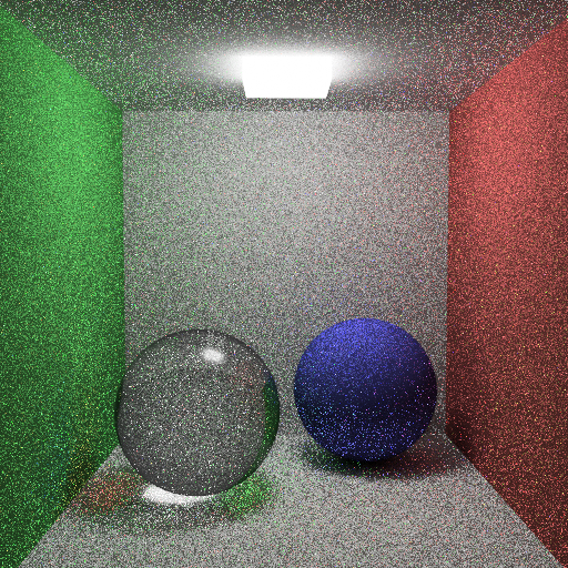
Path tracing glass with next event estimation + importance sampling + Russian roulette output
Other Outputs

Cornellbox jaroslav glossy area light without attenuation output

Cornellbox jaroslav glossy area light with attenuation output

Killeroo Blinn-Phong shading output

Killeroo closeup Blinn-Phong shading output

Killeroo Torrance-Sparrow shading ouput

Killeroo closeup Torrance-Sparrow shading ouput
Bugs

Mesh light self shadowing bug

Ellipsoid light self shadowing bug

Mesh light no self-light bug

Path tracing bug

Russian roulette low throughput bug
Sources
- Akyüz, A. O. (2022). CENG 795 Special Topics: Advanced Ray Tracing. Middle East Technical University.
- https://www.fabrizioduroni.it/2017/08/25/how-to-calculate-reflection-vector/
메타데이터
- post_id
- d68f7b6ad22c
- slug
- ray-tracing-from-scratch-brdfs-object-lights-path-tracing-d68f7b6ad22c
- url
- https://medium.com/@muhammedcan.erbudak/ray-tracing-from-scratch-brdfs-object-lights-path-tracing-d68f7b6ad22c
- canonical_url
- https://medium.com/@muhammedcan.erbudak/ray-tracing-from-scratch-brdfs-object-lights-path-tracing-d68f7b6ad22c
- author_url
- https://medium.com/@muhammedcan.erbudak
- status
- ok
- fetched_at
- 2026-07-26 05:38:51