Python Radio 20: The CC1101 Module
Half a megabit per second over a kilometer.
Python Radio 20: The CC1101 Module
Half a megabit per second over a kilometer.
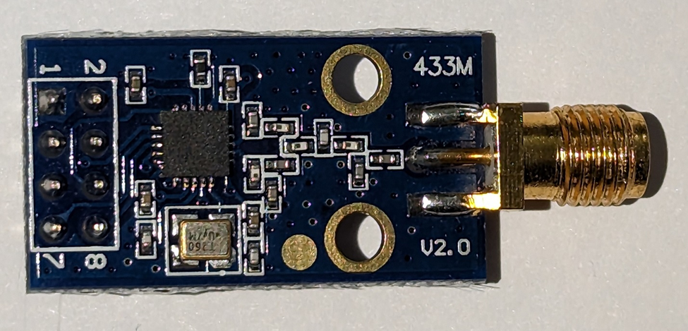
Photo by the author
The CC1101 is a very flexible sub-gigahertz transceiver. It can transmit and receive in three wide frequency ranges: 300 to 348 MHz, 387 to 464 MHz, and 779 to 928 Mhz. That middle range includes the European license-free ISM band (433.05 MHz to 434.79 MHz), as well as the U.S. Amateur Radio 70 cm band (420 to 450 MHz). That means that with an Amateur Radio license, you can amplify the CC1101’s 10-milliwatt output to as much as 50 watts (but as most communication in this band is line-of-sight, 5 watts is usually more than enough).
The last band includes the European 868 MHz license-free ISM band (863 MHz to 870 MHz) and U.S. 915 Mhz license-free ISM band (902 MHz to 928 MHz).
10-milliwatts can reach a kilometer between two CC1101’s in the open with good antennas placed high above the ground.
Modules containing the chip are usually limited to one of the three ranges. In this section, we will use the 433 MHz version that can reach the U.S. Amateur Radio frequencies.
The module is programmed using the SPI (Serial Peripheral Interface), which needs 5 pins (power, ground, clock, input, and output) as well as a chip select pin, and two general purpose pins called GDO0 and GDO2.
With 8 pins to worry about, this is already one of our most complicated modules. But it doesn’t stop there. There are 47 configuration registers, 13 status registers, and many modes and functions.
The chip can support synchronous and asynchronous serial modes up to half a megabit, and packetized modes with cyclic redundancy checks, preambles, sync words, forward error correction, interleaving, and more.

Image by the author
Because of this complexity, even something as simple as our Morse code transmitter and receiver takes quite a bit of configuring.
The code for the main.py module sets up the SPI interface and is divided into two sections we will call “alice” and “bob”:
from machine import SoftSPI, SPI, Pin, PWM
from cc1101 import CC1101
from whoami import whoami
from whoami import my_address
from time import sleep

def main():
  global radio
  spi = SoftSPI(baudrate=200_000, sck=Pin(2), mosi=Pin(3), miso=Pin(4), firstbit=SPI.MSB)
  print(”I am”, whoami)

  if whoami == “alice”:
    from morse import Morse
    gdo0 = Pin(17, Pin.OUT)
    gdo2 = Pin(18, Pin.OUT)
    cs   = Pin( 5, Pin.OUT)
    radio = CC1101( spi, cs, gdo0, gdo2, 433_920_000 )
    morse = Morse(radio)
    morse.speed(20)
    radio.transmit()
    while True:
      morse.send(”Hello, world! This is AB6NY sending via a cc1101 at 10 milliwatts.”)
      sleep(1)
  elif whoami == “bob”:
    gdo0 = Pin(17, Pin.OUT)
    gdo2 = Pin(18, Pin.IN)
    cs   = Pin( 5, Pin.OUT)
    radio = CC1101( spi, cs, gdo0, gdo2, 433_920_000 )
    radio.receive()
    speaker = PWM(Pin(13), freq=800, duty_u16=0)
    while True:
      if gdo2.value():
        speaker.duty_u16(32768)
      else:
        speaker.duty_u16(0)

    sleep(60 * 60 * 24 * 365 * 100)   # Should be long enough

main()
Alice is the transmitter. All of the pins are outputs.
Bob is the receiver. The GDO2 pin is an input and will go high when the CC1101 detects a carrier from Alice. When it does, Bob will send a square wave to the speaker attached to pin 13, and the user will hear an 800-hertz tone.
The morse.py module is only slightly changed. It simply calls the on() and off() methods of the radio module.
class Morse:
  def __init__(self, radio):
    self.radio = radio
    self.character_speed = 5

  def speed(self, overall_speed):
    self.character_speed = overall_speed
    units_per_minute = int(self.character_speed * 50)        # The word PARIS is 50 units of time
    OVERHEAD = 2
    self.DOT = int(60000 / units_per_minute) - OVERHEAD
    self.DASH = 3 * self.DOT
    self.CYPHER_SPACE = self.DOT

    self.LETTER_SPACE = int(3 * self.DOT) - self.CYPHER_SPACE
    self.WORD_SPACE = int(7 * self.DOT) - self.CYPHER_SPACE

  def send(self, str):
    from the_code import code
    from time import sleep_ms
    for c in str:
      if c == ‘ ‘:
        self.radio.off()
        sleep_ms(self.WORD_SPACE)
      else:
        cyphers = code[c.upper()]
        for x in cyphers:
          if x == ‘.’:
            self.radio.on()
            sleep_ms(self.DOT)
          else:
            self.radio.on()
            sleep_ms(self.DASH)
          self.radio.off()
          sleep_ms(self.CYPHER_SPACE)
        self.radio.off()
        sleep_ms(self.LETTER_SPACE)
Our the_code.py module has not changed.
As you might expect, most of the complexity resides in the cc1101.py module:
from time import sleep, sleep_ms, sleep_us
from machine import Pin, SPI

class StrobeAddress():
  SRES = 0x30
  SFSTXON = 0x31
  SXOFF = 0x32
  SCAL = 0x33
  SRX = 0x34
  STX = 0x35
  SIDLE = 0x36
  SWOR = 0x38
  SPWD = 0x39
  SFRX = 0x3A
  SFTX = 0x3B
  SWORRST = 0x3C
  SNOP = 0x3D

class StatusRegisterAddress:
  PARTNUM = 0xF0         # Part number for CC1101
  VERSION = 0xF1         # Current version number
  FREQEST = 0xF2         # Frequency Offset Estimate
  LQI = 0xF3             # Demodulator estimate for Link Quality
  RSSI = 0xF4            # Received signal strength indication
  MARCSTATE = 0xF5       # Control state machine state
  WORTIME1 = 0xF6        # High byte of WOR timer
  WORTIME0 = 0xF7        # Low byte of WOR timer
  PKTSTATUS = 0xF8       # Current GDOx status and packet status
  VCO_VC_DAC = 0xF9      # Current setting from PLL calibration module
  TXBYTES = 0xFA         # Underflow and number of bytes in the TX FIFO
  RXBYTES = 0xFB         # Overflow and number of bytes in the RX FIFO
  RCCTRL1_STATUS = 0xFC  # Last RC oscillator calibration result
  RCCTRL0_STATUS = 0xFD  # Last RC oscillator calibration result

class ConfigurationRegisterAddress:
  IOCFG2 = 0x00          # GDO2 output pin configuration
  IOCFG1 = 0x01          # GDO1 output pin configuration
  IOCFG0 = 0x02          # GDO0 output pin configuration
  FIFOTHR = 0x03         # RX FIFO and TX FIFO thresholds
  SYNC1 = 0x04           # Sync word, high byte
  SYNC0 = 0x05           # Sync word, low byte
  PKTLEN = 0x06          # Packet length
  PKTCTRL1 = 0x07        # Packet automation control
  PKTCTRL0 = 0x08        # Packet automation control
  ADDR = 0x09            # Device address
  CHANNR = 0x0A          # Channel number
  FSCTRL1 = 0x0B         # Frequency synthesizer control
  FSCTRL0 = 0x0C         # Frequency synthesizer control
  FREQ2 = 0x0D           # Frequency control word, high byte
  FREQ1 = 0x0E           # Frequency control word, middle byte
  FREQ0 = 0x0F           # Frequency control word, low byte
  MDMCFG4 = 0x10         # Modem configuration
  MDMCFG3 = 0x11         # Modem configuration
  MDMCFG2 = 0x12         # Modem configuration
  MDMCFG1 = 0x13         # Modem configuration
  MDMCFG0 = 0x14         # Modem configuration
  DEVIATN = 0x15         # Modem deviation setting
  MCSM2 = 0x16           # Main Radio Control State Machine configuration
  MCSM1 = 0x17           # Main Radio Control State Machine configuration
  MCSM0 = 0x18           # Main Radio Control State Machine configuration
  FOCCFG = 0x19          # Frequency Offset Compensation configuration
  BSCFG = 0x1A           # Bit Synchronization configuration
  AGCTRL2 = 0x1B         # AGC control
  AGCTRL1 = 0x1C         # AGC control
  AGCTRL0 = 0x1D         # AGC control
  WOREVT1 = 0x1E         # High byte Event 0 timeout
  WOREVT0 = 0x1F         # Low byte Event 0 timeout
  WORCTRL = 0x20         # Wake On Radio control
  FREND1 = 0x21          # Front end RX configuration
  FREND0 = 0x22          # Front end TX configuration
  FSCAL3 = 0x23          # Frequency synthesizer calibration
  FSCAL2 = 0x24          # Frequency synthesizer calibration
  FSCAL1 = 0x25          # Frequency synthesizer calibration
  FSCAL0 = 0x26          # Frequency synthesizer calibration
  RCCTRL1 = 0x27         # RC oscillator configuration
  RCCTRL0 = 0x28         # RC oscillator configuration
  FSTEST = 0x29          # Frequency synthesizer calibration control
  PTEST = 0x2A           # Production test
  AGCTEST = 0x2B         # AGC test
  TEST2 = 0x2C           # Various test settings
  TEST1 = 0x2D           # Various test settings
  TEST0 = 0x2E           # Various test settings

class PatableAddress:
  PATABLE = 0x3E

class FIFORegisterAddress:
  TX = 0x3F
  RX = 0x3F

patable_power_433 = [0x00,0x6C,0x6C,0x6C,0x6C,0x6C,0x6C,0x6C]

WRITE_SINGLE      = 0x00
WRITE_BURST       = 0x40
READ_SINGLE       = 0x80
READ_BURST        = 0xC0

IDLE_STATE        = 0
RX_STATE          = 1
TX_STATE          = 2
FSTXON_STATE      = 3
CAL_STATE         = 4
SETTLING_STATE    = 5
RXOVER_STATE      = 6
TXUNDER_STATE     = 7

class SPIDevice:
  def __init__(self, spi, cs):
    self.buf = bytearray(1)
    self.spi = spi
    self.cs = cs
    self.state = IDLE_STATE

  def reg_cmd_strobe(self, reg):
    self.cs(0)
    self.spi.readinto(self.buf, reg & 0x3F)
    self.cs(1)
    sleep_ms(1)
    self.get_status(self.buf[0])
    return self.buf[0]

  def reg_read_bytes(self, reg, buf):
    self.cs(0)
    self.spi.readinto(buf, READ_BURST | reg)
    self.spi.readinto(buf)
    self.cs(1)
    sleep_ms(1)
    return buf

  def reg_write(self, reg, value):
    self.cs(0)
    self.spi.readinto(self.buf, WRITE_SINGLE | reg)
    ret = self.buf[0]
    self.get_status(ret)
    self.spi.readinto(self.buf, value)
    self.cs(1)
    sleep_ms(1)
    return ret

  def reg_write_bytes(self, reg, buf):
    self.cs(0)
    self.spi.readinto(self.buf, WRITE_BURST | reg)
    self.get_status(self.buf[0])
    self.spi.write(buf)
    self.cs(1)
    sleep_ms(1)

  def reset(self):
    self.cs(0)
    sleep_ms(100)
    self.cs(1)
    sleep_ms(100)
    status_byte = self.reg_cmd_strobe(StrobeAddress.SRES)
    sleep_ms(100)
    self.get_status(status_byte)
    sleep_ms(1)

  def get_status(self, status_byte):
    self.ready = True
    if 0x80 & status_byte:
      self.ready = False

    s = (0x70 & status_byte) >> 4
    if   s == 0: self.state = IDLE_STATE
    elif s == 1: self.state = RX_STATE
    elif s == 2: self.state = TX_STATE
    elif s == 3: self.state = FSTXON_STATE
    elif s == 4: self.state = CAL_STATE
    elif s == 5: self.state = SETTLING_STATE
    elif s == 6: self.state = RXOVER_STATE
    elif s == 7: self.state = TXUNDER_STATE
    sleep_ms(1)

  def read_status_reg_and_check(self, reg):
    ret = bytearray(1)
    check = bytearray(1)
    while True:
      self.reg_read_bytes(reg, ret)
      self.reg_read_bytes(reg, check)
      if ret == check:
        break

    status_byte = self.reg_cmd_strobe(StrobeAddress.SNOP)
    self.get_status(status_byte)

    return ret[0]

class CC1101:
    def __init__(self, spi, cs, gdo0, gdo2, frequency, catch0=None, catch2=None):
      self.gdo0 = gdo0
      self.gdo2 = gdo2
      self.device = SPIDevice(spi, cs)
      self.device.reset()

      self.device.reg_cmd_strobe(StrobeAddress.SIDLE)
      sleep_us(800)
      self.device.reg_cmd_strobe(StrobeAddress.SFRX)                                         # flush the RX buffer
      self.device.reg_cmd_strobe(StrobeAddress.SFTX)                                         # flush the TX buffer

      self.device.reg_write(ConfigurationRegisterAddress.IOCFG2,   0x0D)
      self.device.reg_write(ConfigurationRegisterAddress.IOCFG0,   0x0D)
      self.device.reg_write(ConfigurationRegisterAddress.FIFOTHR,  0x47)
      self.device.reg_write(ConfigurationRegisterAddress.PKTCTRL0, 0x32)
      self.device.reg_write(ConfigurationRegisterAddress.FSCTRL1,  0x06)
      self.device.reg_write(ConfigurationRegisterAddress.MDMCFG4,  0xF5)
      self.device.reg_write(ConfigurationRegisterAddress.MDMCFG3,  0x75)
      self.device.reg_write(ConfigurationRegisterAddress.MDMCFG2,  0x30)
      self.device.reg_write(ConfigurationRegisterAddress.MDMCFG1,  0x72)
      self.device.reg_write(ConfigurationRegisterAddress.DEVIATN,  0x14)
      self.device.reg_write(ConfigurationRegisterAddress.MCSM0,    0x18)
      self.device.reg_write(ConfigurationRegisterAddress.FOCCFG,   0x16)
      self.device.reg_write(ConfigurationRegisterAddress.WORCTRL,  0xFB)
      self.device.reg_write(ConfigurationRegisterAddress.FREND0,   0x11)
      self.device.reg_write(ConfigurationRegisterAddress.FSCAL3,   0xE9)
      self.device.reg_write(ConfigurationRegisterAddress.FSCAL2,   0x2A)
      self.device.reg_write(ConfigurationRegisterAddress.FSCAL1,   0x00)
      self.device.reg_write(ConfigurationRegisterAddress.FSCAL0,   0x1F)
      self.device.reg_write(ConfigurationRegisterAddress.TEST2,    0x81)
      self.device.reg_write(ConfigurationRegisterAddress.TEST1,    0x35)
      self.device.reg_write(ConfigurationRegisterAddress.TEST0,    0x09)
      self.device.reg_write(ConfigurationRegisterAddress.CHANNR,   0x00)

      self.device.reg_write_bytes(PatableAddress.PATABLE, bytearray(patable_power_433))

      self.set_frequency(frequency)

      self.device.reg_cmd_strobe(StrobeAddress.SCAL)
      sleep_us(800)

      if catch0:
        self.gdo0.irq(catch0, trigger=(Pin.IRQ_FALLING | Pin.IRQ_RISING))

      if catch2:
        self.gdo2.irq(catch2, trigger=Pin.IRQ_FALLING)

    def get_RSSI(self):
      ret = bytearray(1)
      self.device.reg_read_bytes(StatusRegisterAddress.RSSI, ret)
      return ret[0]

    def set_frequency(self, frequency):
      frequency_hex = hex(int(frequency * (65536 / 26_000_000)))

      byte2 = (int(frequency_hex, 16) >> 16) & 0xff
      byte1 = (int(frequency_hex) >>  8) & 0xff
      byte0 = int(frequency_hex) & 0xff

      self.device.reg_write(ConfigurationRegisterAddress.FREQ2, byte2)
      self.device.reg_write(ConfigurationRegisterAddress.FREQ1, byte1)
      self.device.reg_write(ConfigurationRegisterAddress.FREQ0, byte0)

    def transmit(self):
      self.device.reg_cmd_strobe(StrobeAddress.SIDLE)
      sleep_us(800)
      self.device.reg_cmd_strobe(StrobeAddress.SCAL)
      sleep_us(800)

      while self.device.state != IDLE_STATE:
        self.device.reg_cmd_strobe(StrobeAddress.SNOP)

      while self.device.state != TX_STATE:
        status_byte = self.device.reg_cmd_strobe(StrobeAddress.STX)                    ### Start transmitting
        self.device.read_status_reg_and_check(StatusRegisterAddress.TXBYTES)           ### Won’t transmit without this, don’t know why
        if self.device.state == TXUNDER_STATE:
          status_byte = self.device.reg_cmd_strobe(StrobeAddress.SFTX)

      txBytes = self.device.read_status_reg_and_check(StatusRegisterAddress.TXBYTES)

      while self.device.state != IDLE_STATE and txBytes > 0:
        txBytes = self.device.read_status_reg_and_check(StatusRegisterAddress.TXBYTES)
        self.device.reg_cmd_strobe(StrobeAddress.SNOP)

      if self.device.state == TXUNDER_STATE:
        status_byte = self.device.reg_cmd_strobe(StrobeAddress.SFTX)

      sleep_us(100)

    def receive(self):
      self.device.reg_cmd_strobe(StrobeAddress.SIDLE)
      sleep_us(800)
      self.device.reg_cmd_strobe(StrobeAddress.SCAL)
      sleep_us(800)

      while self.device.state != RX_STATE:
        status_byte = self.device.reg_cmd_strobe(StrobeAddress.SRX)

        cnt = self.device.read_status_reg_and_check(StatusRegisterAddress.RXBYTES)
        if self.device.state == RXOVER_STATE or (cnt & 0x80):
          self.device.reg_cmd_strobe(StrobeAddress.SFRX)
        sleep_us(100)

    def on(self):
      self.gdo0.value(1)

    def off(self):
      self.gdo0.value(0)
The addresses of the 13 commands are found in the StrobeAddress class, and the addresses of the 13 status registers are seen in the StatusRegisterAddress class. The 47 configuration registers are in the ConfigurationRegisterAddress class. Two other classes hold the address of the 8-byte Power Amplifier table, and the address of the FIFO buffer for transmitting and receiving up to 64 bytes.
The SPIDevice class is used to send and receive data between the microprocessor and the CC1101 module. It handles setting and resetting the Chip Select pin, getting the status byte returned from commands, and details of timing.
The CC1101 class is the device driver for the module. It resets the CC1101, flushes anything in the transmit and receive buffers, and sets a number of configuration registers to set up the chip to send an unmodulated (CW) signal. Texas Instruments, the company that designed the chip, has free software for setting up all of these registers. The software is called the SmartRF Studio.
The Power Amplifier table determines the output power for each of 8 parts of each bit to be sent. By shaping the amplitude of a bit in this way, the transmitter can avoid sending out power into unwanted sidebands and thus interfering with other radios on nearby channels. Our PATABLE doesn’t use this feature (since we aren’t sending bits), so it has zero power in the first byte and 0x6C (full power) in the seven ramaining bytes.
It then sets the frequency and calibrates the oscillator. We don’t use the catch0 and catch2 arguments when sending and receiving CW.
The transmit() and receive() methods set the module into those respective modes. This process involves setting the chip into the IDLE state, calibrating the oscillator, sending the STX or SRX command, and waiting for any pending bytes from previous commands to be processed (there won’t be any, since we are sending CW, not bits and bytes). It also flushes the FIFO buffers if there was an error condition (there won’t be in CW).
Finally, the on() and off() methods control whether the transmitter is transmitting or not by sending a signal on the GDO0 pin.
Altogether, almost 300 lines of code just to turn the transmitter on and off. While the module is capable of doing this job, it is not what it was designed for. It wants to send bytes and packets, and at much higher speeds. Let’s let it do that.
The RP2040’s UART can send bytes at just under a megabit per second (961.6 kBaud). Our CC1101 can manage half a megabit (500 kBaud) in MSK mode and a quarter megabit (250 kBaud) in GFSK mode. At my location, I was getting occasional interference at the highest baud rate from some nearby transmitter (the 433 MHz band is shared with lots of different devices), but at 250 kBaud I was getting no errors at all after the first message was sent (the first message accumulates a lot of noise as the receiver waits for the transmitter to begin).
The main.py module for sending UART bits through the CC1101 looks like this:
from machine import SoftSPI, SPI, Pin, UART
from cc1101 import CC1101
from whoami import whoami
from whoami import my_address
from time import sleep

def main():
  global radio
  spi = SoftSPI(baudrate=200_000, sck=Pin(2), mosi=Pin(3), miso=Pin(4), firstbit=SPI.MSB)
  print(”I am”, whoami)
  baud = 250_000

  if whoami == “alice”:
    gdo0 = Pin(8, Pin.OUT)
    gdo2 = Pin(18, Pin.OUT)
    cs   = Pin( 5, Pin.OUT)
    radio = CC1101( spi, cs, gdo0, gdo2, 433_920_000, baud )
    serial = UART(1, baudrate=baud, tx=gdo0, rx=Pin(9, Pin.IN))
    radio.transmit()
    count = 0
    preamble = “UUUUABCD”
    while True:
      serial.write(preamble + str(count) + “: Hello, world! This is AB6NY sending via a cc1101 at 10 milliwatts.\n”)
      count += 1
      sleep(1)
  elif whoami == “bob”:
    gdo0 = Pin(17, Pin.OUT)
    gdo2 = Pin(9, Pin.IN)
    cs   = Pin( 5, Pin.OUT)
    radio = CC1101( spi, cs, gdo0, gdo2, 433_920_000, baud )
    serial = UART(1, baudrate=baud, tx=Pin(8), rx=gdo2)
    radio.receive()
    while True:
      if serial.any():
        s = serial.read()
        try:
          msg = s.decode(’utf-8’)
          index = msg.find(”ABCD”)
          if index > 0:
            print(msg[index+4:], end=”)
#         else:
#           print(”No sync:”, msg, end=”)
#       except:
#         print(”Not utf-8:”, s, end=”)

main()
We have added an argument to the CC1101 driver: it now needs to know the baud rate. The transmitter (Alice) sets the UART tx pin to the same pin as GDO0. Alice does not care about the UART receive pin, but sets it to 9 anyway.
The preamble and sync word are probably not necessary for most baud rates, but I found it useful for the 500 kBaud rate, as the first bits of the message were often corrupted. The preamble is just a set of alternating zero and one bits to help synchronize the receiver. That is the four capital U characters. The ABCD is a synchronization sequence to tell us where the real data payload is. In packet modes, the preamble synchronizes at the bit level, and the sync word aligns the bytes.
The receiver (Bob) sets the UART receive pin to the same as GDO2. The CC1101 thus uses GDO0 for data in and GDO2 for data out. The UART (of course) sends on GDO0 and receives on GDO2.
Bob waits for serial data to be available, and then reads it. If it is uncorrupted utf-8 and the sync word is found, it prints the payload.
The cc1101.py module’s only changes are to the PATABLE and the init() method:
class CC1101:
    def __init__(self, spi, cs, gdo0, gdo2, frequency, baud, catch0=None, catch2=None):
      self.gdo0 = gdo0
      self.gdo2 = gdo2
      self.device = SPIDevice(spi, cs)
      self.device.reset()

      self.device.reg_cmd_strobe(StrobeAddress.SIDLE)
      sleep_us(800)
      self.device.reg_cmd_strobe(StrobeAddress.SFRX)                                         # flush the RX buffer
      self.device.reg_cmd_strobe(StrobeAddress.SFTX)                                         # flush the TX buffer

      self.device.reg_write(ConfigurationRegisterAddress.IOCFG2,   0x0D)
      self.device.reg_write(ConfigurationRegisterAddress.IOCFG0,   0x0D)
      self.device.reg_write(ConfigurationRegisterAddress.FIFOTHR,  0x47)
      self.device.reg_write(ConfigurationRegisterAddress.PKTCTRL0, 0x32)
      self.device.reg_write(ConfigurationRegisterAddress.FSCTRL1,  0x06)
      self.device.reg_write(ConfigurationRegisterAddress.MCSM0,    0x18)
      self.device.reg_write(ConfigurationRegisterAddress.FOCCFG,   0x16)
      self.device.reg_write(ConfigurationRegisterAddress.WORCTRL,  0xFB)
      self.device.reg_write(ConfigurationRegisterAddress.FSCAL3,   0xE9)
      self.device.reg_write(ConfigurationRegisterAddress.FSCAL2,   0x2A)
      self.device.reg_write(ConfigurationRegisterAddress.FSCAL1,   0x00)
      self.device.reg_write(ConfigurationRegisterAddress.FSCAL0,   0x1F)
      self.device.reg_write(ConfigurationRegisterAddress.TEST2,    0x81)
      self.device.reg_write(ConfigurationRegisterAddress.TEST1,    0x35)
      self.device.reg_write(ConfigurationRegisterAddress.TEST0,    0x09)
      self.device.reg_write(ConfigurationRegisterAddress.CHANNR,   0x00)

      if baud == 1200:
        self.device.reg_write(ConfigurationRegisterAddress.MDMCFG4,  0xF5)
        self.device.reg_write(ConfigurationRegisterAddress.MDMCFG3,  0x75)
        self.device.reg_write(ConfigurationRegisterAddress.MDMCFG2,  0x30)
        self.device.reg_write(ConfigurationRegisterAddress.MDMCFG1,  0x72)
        self.device.reg_write(ConfigurationRegisterAddress.DEVIATN,  0x14)
        self.device.reg_write(ConfigurationRegisterAddress.FREND0,   0x11)
      elif baud == 38400:
        self.device.reg_write(ConfigurationRegisterAddress.MDMCFG4,  0xCA)
        self.device.reg_write(ConfigurationRegisterAddress.MDMCFG3,  0x83)
        self.device.reg_write(ConfigurationRegisterAddress.MDMCFG2,  0x10)
        self.device.reg_write(ConfigurationRegisterAddress.DEVIATN,  0x35)
        self.device.reg_write(ConfigurationRegisterAddress.FREND0,   0x17)
        self.device.reg_write(ConfigurationRegisterAddress.AGCTRL2,  0x43)
      elif baud == 76800:
        self.device.reg_write(ConfigurationRegisterAddress.FSCTRL1,  0x08)
        self.device.reg_write(ConfigurationRegisterAddress.MDMCFG4,  0x7B)
        self.device.reg_write(ConfigurationRegisterAddress.MDMCFG3,  0x83)
        self.device.reg_write(ConfigurationRegisterAddress.MDMCFG2,  0x10)
        self.device.reg_write(ConfigurationRegisterAddress.DEVIATN,  0x42)
        self.device.reg_write(ConfigurationRegisterAddress.FOCCFG,   0x1D)
        self.device.reg_write(ConfigurationRegisterAddress.BSCFG,    0x1C)
        self.device.reg_write(ConfigurationRegisterAddress.AGCTRL2,  0xC7)
        self.device.reg_write(ConfigurationRegisterAddress.AGCTRL1,  0x00)
        self.device.reg_write(ConfigurationRegisterAddress.AGCTRL0,  0xB2)
        self.device.reg_write(ConfigurationRegisterAddress.FREND0,   0x17)
        self.device.reg_write(ConfigurationRegisterAddress.FREND1,   0xB6)
        self.device.reg_write(ConfigurationRegisterAddress.FSCAL3,   0xEA)
      elif baud == 100000:
        self.device.reg_write(ConfigurationRegisterAddress.FSCTRL1,  0x08)
        self.device.reg_write(ConfigurationRegisterAddress.MDMCFG4,  0x5B)
        self.device.reg_write(ConfigurationRegisterAddress.MDMCFG3,  0xF8)
        self.device.reg_write(ConfigurationRegisterAddress.MDMCFG2,  0x10)
        self.device.reg_write(ConfigurationRegisterAddress.DEVIATN,  0x47)
        self.device.reg_write(ConfigurationRegisterAddress.FOCCFG,   0x1D)
        self.device.reg_write(ConfigurationRegisterAddress.BSCFG,    0x1C)
        self.device.reg_write(ConfigurationRegisterAddress.AGCTRL2,  0xC7)
        self.device.reg_write(ConfigurationRegisterAddress.AGCTRL1,  0x00)
        self.device.reg_write(ConfigurationRegisterAddress.AGCTRL0,  0xB2)
        self.device.reg_write(ConfigurationRegisterAddress.FREND0,   0x17)
        self.device.reg_write(ConfigurationRegisterAddress.FREND1,   0xB6)
        self.device.reg_write(ConfigurationRegisterAddress.FSCAL3,   0xEA)
      elif baud == 250000:
        self.device.reg_write(ConfigurationRegisterAddress.FSCTRL1,  0x0C)
        self.device.reg_write(ConfigurationRegisterAddress.MDMCFG4,  0x2D)
        self.device.reg_write(ConfigurationRegisterAddress.MDMCFG3,  0x3B)
        self.device.reg_write(ConfigurationRegisterAddress.MDMCFG2,  0x10)
        self.device.reg_write(ConfigurationRegisterAddress.DEVIATN,  0x62)
        self.device.reg_write(ConfigurationRegisterAddress.FOCCFG,   0x1D)
        self.device.reg_write(ConfigurationRegisterAddress.BSCFG,    0x1C)
        self.device.reg_write(ConfigurationRegisterAddress.AGCTRL2,  0xC7)
        self.device.reg_write(ConfigurationRegisterAddress.AGCTRL1,  0x00)
        self.device.reg_write(ConfigurationRegisterAddress.AGCTRL0,  0xB0)
        self.device.reg_write(ConfigurationRegisterAddress.FREND0,   0x17)
        self.device.reg_write(ConfigurationRegisterAddress.FREND1,   0xB6)
        self.device.reg_write(ConfigurationRegisterAddress.FSCAL3,   0xEA)
      elif baud == 500000:  # MSK
        self.device.reg_write(ConfigurationRegisterAddress.FSCTRL1,  0x0E)
        self.device.reg_write(ConfigurationRegisterAddress.MDMCFG4,  0x0E)
        self.device.reg_write(ConfigurationRegisterAddress.MDMCFG3,  0x3B)
        self.device.reg_write(ConfigurationRegisterAddress.MDMCFG2,  0x70)
        self.device.reg_write(ConfigurationRegisterAddress.DEVIATN,  0x00)
        self.device.reg_write(ConfigurationRegisterAddress.FOCCFG,   0x1D)
        self.device.reg_write(ConfigurationRegisterAddress.BSCFG,    0x1C)
        self.device.reg_write(ConfigurationRegisterAddress.AGCTRL2,  0xC7)
        self.device.reg_write(ConfigurationRegisterAddress.AGCTRL1,  0x00)
        self.device.reg_write(ConfigurationRegisterAddress.AGCTRL0,  0xB0)
        self.device.reg_write(ConfigurationRegisterAddress.FREND0,   0x17)
        self.device.reg_write(ConfigurationRegisterAddress.FREND1,   0xB6)
        self.device.reg_write(ConfigurationRegisterAddress.FSCAL3,   0xEA)

      self.device.reg_write_bytes(PatableAddress.PATABLE, bytearray(patable_power_433))

      self.set_frequency(frequency)

      self.device.reg_cmd_strobe(StrobeAddress.SCAL)
      sleep_us(800)

      if catch0:
        self.gdo0.irq(catch0, trigger=(Pin.IRQ_FALLING | Pin.IRQ_RISING))

      if catch2:
        self.gdo2.irq(catch2, trigger=Pin.IRQ_FALLING)
patable_power_433 = [0x00,0x12,0x0E,0x34,0x60,0xC5,0xC1,0xC0] Many of the configuration registers changed, and each baud rate causes even more to change. But beyond that, everything else is the same.
The radio is now happily sending and receiving bytes at 250,000 bits per second (25,000 bytes per second).
The whoami.py module:
class WhoAmI:
    def __init__(self):
        self.me = {}
        try:
            with open("whoami.cfg","rb") as f:
                line = f.read(1024)
                from json import loads
                self.me = loads(line)
        except OSError as e:
            print("Error reading whoami.cfg:", e )
def name(self):
if "name" in self.me:
return self.me["name"]
return "Unknown" def ssid(self):
if "ssid" in self.me:
return self.me["ssid"]
return None def ip(self):
if "ip" in self.me:
return self.me["ip"]
return None def mask(self):
if "mask" in self.me:
return self.me["mask"]
return None def gateway(self):
if "gateway" in self.me:
return self.me["gateway"]
return None def dns(self):
if "dns" in self.me:
return self.me["dns"]
return None def neo_pin(self):
if "neo_pin" in self.me:
return self.me["neo_pin"]
return None def neo_how_many(self):
if "neo_how_many" in self.me:
return self.me["neo_how_many"]
return None def set_ip(self, sta):
if "ip" in self.me:
sta.ifconfig((self.me["ip"], self.me["mask"], self.me["gateway"], self.me["dns"]))The whoami.cfg file for the transmitter:
{"name":"Alice","ssid":"BirdfarmOffice2"}And for the receiver:
{"name":"Bob","ssid":"BirdfarmOffice2"}As usual, change BirdfarmOffice2 to your own SSID. In this project, we aren’t using Wi-Fi, so it doesn’t really matter.
메타데이터
- post_id
- dd94bf0b09b8
- slug
- python-radio-20-the-cc1101-module-dd94bf0b09b8
- url
- https://radiohackers.com/python-radio-20-the-cc1101-module-dd94bf0b09b8
- canonical_url
- https://radiohackers.com/python-radio-20-the-cc1101-module-dd94bf0b09b8
- author_url
- https://medium.com/@simon.field_37276
- status
- ok
- fetched_at
- 2026-07-31 11:34:07