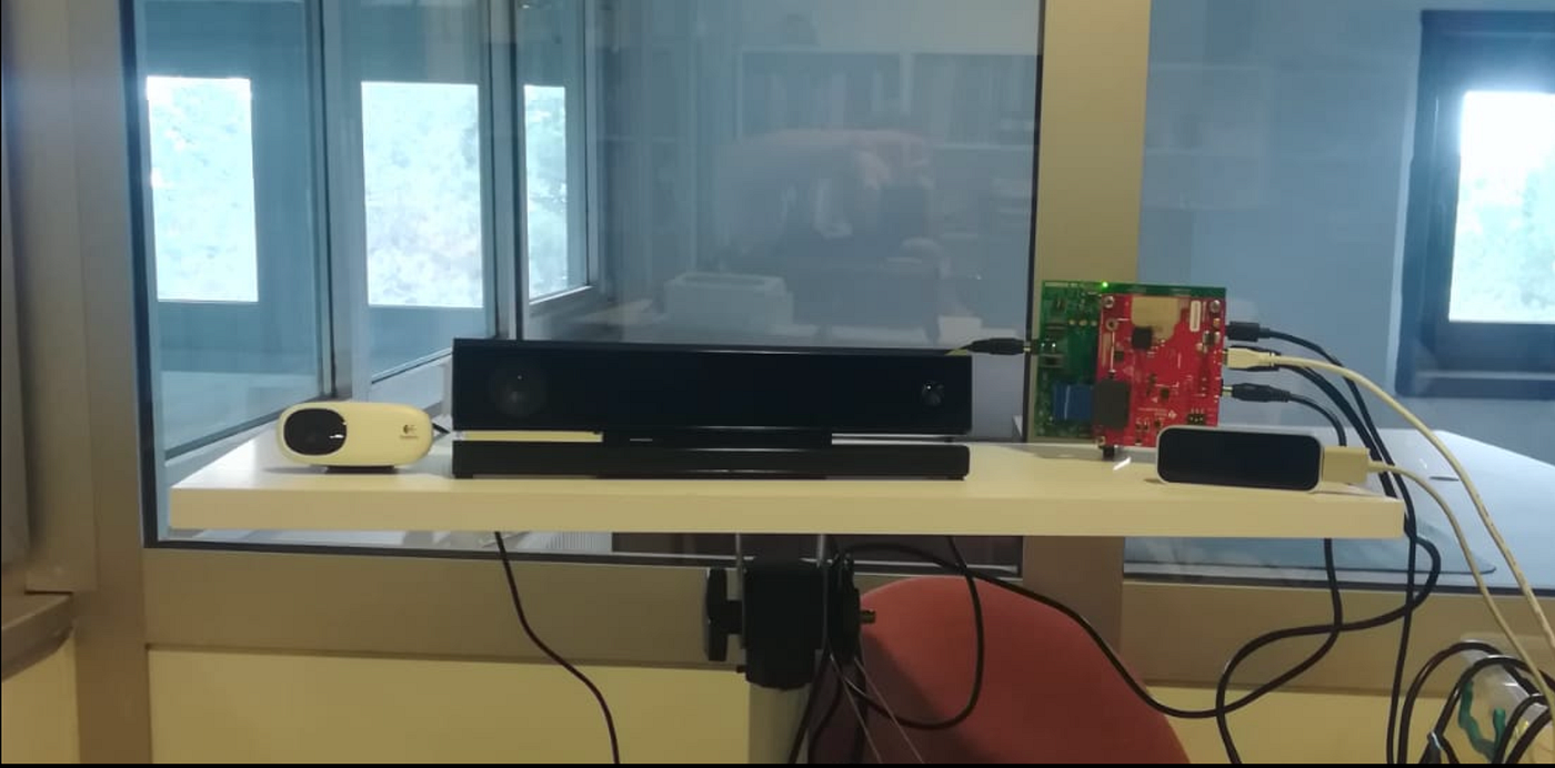
Practical Guide to MmWave Radar Configuration Parameters: Explained with Tips
Introduction
Practical Guide to MmWave Radar Configuration Parameters: Explained with Tips
Introduction
Configuring a mmWave radar properly is the foundation for reliable sensing and accurate downstream processing. The Texas Instruments xWR18xx devices allow fine-grained control of RF parameters such as chirp design, ADC sampling, frame timing, CFAR thresholds, and angle-of-arrival windows. However, the raw configuration files generated by tools like the TI Visualizer often contain redundant or confusing details that can be difficult to adapt for research and development.

This article presents a cleaned and annotated configuration template tailored for SDK 3.05 and xWR18xx platforms operating at 77 GHz. The configuration is optimized for gesture recognition and short-range sensing, balancing range resolution (≈3.9 cm), maximum unambiguous range (≈12 m), and velocity resolution (≈0.12 m/s) at ~30 frames per second.
By walking through the key parameters — profileCfg, chirpCfg, frameCfg, cfarCfg, and more—we explain what each command does, why it matters, and how you can adjust it for your own application. We also provide practical tips to reduce clutter, manage UART bandwidth, and ensure stable performance in real-world environments.
Whether you are a researcher building datasets, a developer integrating radar into HCI or robotics, or a student learning about mmWave sensing, this guide offers a ready-to-use baseline configuration with clear notes and best practices.
Where These Parameters Are Used and Who Needs Them
The configuration parameters described above are essential for anyone working with TI mmWave radars (xWR14xx, xWR16xx, xWR18xx, or similar platforms). They directly control how the sensor transmits chirps, receives echoes, and interprets the resulting point clouds. In practice, these settings determine the radar’s resolution, field of view, maximum range, and detection reliability.
Typical Use Cases
- Gesture recognition and Human–Computer Interaction (HCI): Short-range sensing with fine range resolution enables robust detection of hand, arm, or body movements.
- Robotics and autonomous systems: Robots and drones require precise radar parameters to perceive nearby obstacles, estimate velocities, and operate in low-visibility conditions.
- Healthcare and rehabilitation: Radar systems configured with high sensitivity and static clutter removal can track patient movements for contactless monitoring or rehabilitation exercises.
- Smart environments: Parameters like
cfarCfgandclutterRemovalare key when deploying radars in homes, offices, or industrial sites for presence detection and occupancy sensing. - Research and education: Students and researchers rely on these templates to understand RF trade-offs, build datasets, and experiment with different radar signal processing pipelines.
Who Benefits from This Guide
- Radar engineers and system integrators tuning devices for custom applications.
- AI/ML researchers who need reproducible, well-structured radar data for model training.
- Graduate and undergraduate students in electrical engineering, computer engineering, or robotics, looking for a baseline config to start experiments without struggling with undocumented parameters.
- Startups and developers prototyping contactless interfaces, security systems, or health-tech solutions that demand privacy-preserving sensing.
In short, these parameters are not just numbers in a .cfg file—they are the bridge between raw hardware capability and real-world applications. Proper configuration ensures that the radar delivers clean, consistent, and usable data for whichever task you design it for.
Parameter Explanations
- sensorStop — Stops the radar sensor safely before reconfiguration.
- flushCfg — Clears all previously loaded configuration settings.
- dfeDataOutputMode — Selects the data output mode. (1 = frame-based chirps, 3 = advanced frame).
- channelCfg — Configures active antennas. First value: Rx mask (which receivers are enabled), second: Tx mask (which transmitters are active), third: cascading mode (0 for standalone).
- adcCfg — Defines ADC resolution and output format (e.g., 16-bit, complex samples).
- adcbufCfg — Sets ADC buffer format, IQ swap, interleaving mode, and ping/pong threshold.
- profileCfg — Defines the radar signal profile: start frequency, idle time, ADC start time, ramp time, slope, number of ADC samples, sampling rate, and RX gain. This determines range resolution, max range, and SNR.
- chirpCfg — Defines individual chirp signals, including start/end index, profile ID, variations, and TX antenna mask. Used to enable TDM-MIMO (Tx1, Tx2, Tx3).
- frameCfg — Sets the frame structure: chirp indices, number of loops, number of frames, frame periodicity, trigger type, and trigger delay. Determines FPS and processing load.
- lowPower — Configures ADC power mode (regular or low power).
- guiMonitor — Selects which outputs are streamed: detected objects, side info (SNR, noise), range profile, heat maps, and statistics. Directly affects UART bandwidth.
- cfarCfg — Configures CFAR detection (range and Doppler): averaging mode (CA, CAGO, CASO), noise window, guard length, threshold scale, and peak grouping. Critical for detection reliability.
- multiObjBeamForming — Enables multiple object detection per range bin using beamforming and sets the threshold for secondary peaks.
- clutterRemoval — Removes static objects (like walls or furniture) to highlight moving targets.
- calibDcRangeSig — Calibrates and removes DC offsets from the radar signal (caused by static reflections close to the radar).
- extendedMaxVelocity — Extends the unambiguous velocity range by using multiple chirps (kept disabled here).
- lvdsStreamCfg — Configures LVDS streaming output (disabled unless raw data capture is needed).
- compRangeBiasAndRxChanPhase — Applies calibration to correct range bias and Rx channel phase mismatches.
- measureRangeBiasAndRxChanPhase — Measures bias and channel phase error using a calibration target. Used only in calibration profiles.
- CQRxSatMonitor — Monitors receiver saturation to detect clipping or overdrive.
- CQSigImgMonitor — Monitors the quality of the signal image for debugging and validation.
- analogMonitor — Enables monitoring of analog front-end signals for diagnostics.
- aoaFovCfg — Defines the field of view in azimuth and elevation angles (e.g., -90° to +90°).
- cfarFovCfg — Defines the range and Doppler limits within which CFAR detections are valid.
- calibData — Placeholder for calibration data import.
- sensorStart — Starts the sensor with the loaded configuration.
Quick Example Config (Indoor, Short Range)
Explanation
The Quick Example Config (Indoor, Short Range) provides a ready-to-use parameter set optimized for laboratory experiments, gesture recognition, and indoor tracking scenarios. This setup limits the maximum range to approximately 12 meters, which is more than sufficient for small rooms, offices, or smart home applications. By focusing on shorter ranges, the configuration achieves higher range resolution (~4 cm), allowing the system to distinguish fine movements such as hand gestures or subtle body shifts.
In addition, the configuration is designed to maintain 30 frames per second (fps), which ensures smooth and responsive detection without overloading the processing pipeline. Features like clutter removal help eliminate static reflections (e.g., from walls or furniture), while multi-object beamforming ensures that multiple targets can still be tracked simultaneously in confined indoor environments. As a result, this configuration strikes a balance between accuracy, responsiveness, and efficiency, making it ideal for academic research, prototyping, and real-world IoT applications indoors.
Why this config?
- Short range (≤12 m): Good for labs, gesture recognition, occupancy.
- High resolution (≈4 cm): Thanks to steep slope and 256 ADC samples.
- 30 fps: Smooth motion tracking without CPU overload.
- Clutter removal: Removes walls and static objects for cleaner detection.
%Quick Example Config (Indoor, Short Range)
sensorStop
flushCfg
dfeDataOutputMode 1          % Frame-based chirps

channelCfg 15 7 0            % Enable all 4 Rx + 3 Tx
adcCfg 2 1                   % 16-bit, complex samples
adcbufCfg -1 0 1 1 1

profileCfg 0 77 100 7 60 0 0 60 1 256 2000 0 0 30
% 77 GHz, 60 µs ramp, 60 MHz/us slope
% 256 samples → ~12 m max range
% Range resolution ≈ 0.04 m

chirpCfg 0 2 0 0 0 0 0 7     % Chirp set across Tx1, Tx2, Tx3
frameCfg 0 2 16 0 33.3 1 0   % 16 chirps/frame, 30 fps

lowPower 0 0
guiMonitor -1 1 1 0 0 0 1    % Objects + Range Profile + Stats
cfarCfg -1 0 2 8 4 3 0 15 1  % CFAR in Range
cfarCfg -1 1 0 4 2 3 1 15 1  % CFAR in Doppler
multiObjBeamForming -1 1 0.5 % Enable multiple object detection
clutterRemoval -1 1          % Remove static reflections

sensorStart
MmWave Radar Configuration Parameters
MmWave Radar Configuration Parameters

| **Parameter**                      | **Explanation**                                                            | **Usage Tips**                                                                      |
| ---------------------------------- | -------------------------------------------------------------------------- | ----------------------------------------------------------------------------------- |
| **sensorStop**                     | Stops the radar sensor safely before reconfiguration.                      | Always stop before loading a new config; prevents firmware crashes.                 |
| **flushCfg**                       | Clears all previously loaded configuration settings.                       | Use before a new setup to avoid conflicts with old parameters.                      |
| **dfeDataOutputMode**              | Selects the data output mode (1 = frame-based chirps, 3 = advanced frame). | Most demos use **mode 1**; advanced mode requires custom parsing.                   |
| **channelCfg**                     | Configures active antennas: Rx mask, Tx mask, cascading mode.              | For full FoV, enable all 4 Rx and 3 Tx (MIMO).                                      |
| **adcCfg**                         | Defines ADC resolution and output format.                                  | 16-bit complex is standard; higher resolution → more data, more bandwidth.          |
| **adcbufCfg**                      | Sets ADC buffer format, IQ swap, interleaving, ping/pong buffer.           | Use IQ swap = 1 to match most demo parsers.                                         |
| **profileCfg**                     | Defines radar signal profile (frequency, slope, samples, rate, gain).      | This is the **heart of radar config** – controls range resolution and max velocity. |
| **chirpCfg**                       | Defines chirp sequences (index, profile ID, Tx mask).                      | Use multiple chirps with different Tx for MIMO operation.                           |
| **frameCfg**                       | Sets frame structure: chirps, loops, frames, period, trigger.              | Lower frame period = higher FPS but more processing load.                           |
| **lowPower**                       | Configures ADC power mode.                                                 | Keep at regular mode unless extreme power saving is required.                       |
| **guiMonitor**                     | Selects outputs to stream (objects, SNR, heatmaps, stats).                 | Be careful: enabling many outputs may **overload UART bandwidth**.                  |
| **cfarCfg**                        | Configures CFAR detection in range/Doppler.                                | Tune guard length + threshold for balancing sensitivity vs false alarms.            |
| **multiObjBeamForming**            | Enables detection of multiple objects per bin.                             | Use if tracking objects close to each other.                                        |
| **clutterRemoval**                 | Removes static reflections.                                                | Enable indoors to filter walls; disable if static targets are important.            |
| **calibDcRangeSig**                | Removes DC bias caused by reflections.                                     | Always recommended to improve accuracy, especially in near range.                   |
| **extendedMaxVelocity**            | Extends velocity measurement range.                                        | Rarely needed; increases complexity and CPU load.                                   |
| **lvdsStreamCfg**                  | Configures raw data streaming.                                             | Enable only for **offline raw data collection** – needs DCA1000.                    |
| **compRangeBiasAndRxChanPhase**    | Applies calibration to correct bias and phase mismatches.                  | Use after running calibration routine with strong reflector.                        |
| **measureRangeBiasAndRxChanPhase** | Measures bias and phase error automatically.                               | Use during calibration setup; then hardcode results in config.                      |
| **CQRxSatMonitor**                 | Monitors receiver saturation.                                              | Helps detect clipping when targets are too close or too strong.                     |
| **CQSigImgMonitor**                | Monitors image quality for debugging.                                      | Enable for lab testing, not needed in production.                                   |
| **analogMonitor**                  | Monitors analog front-end signals.                                         | Advanced debugging only.                                                            |
| **aoaFovCfg**                      | Sets azimuth/elevation field of view.                                      | Narrow FoV = higher accuracy; wide FoV = broader coverage.                          |
| **cfarFovCfg**                     | Defines min/max range & Doppler detection limits.                          | Use to filter out noise outside useful detection region.                            |
| **calibData**                      | Placeholder for calibration data.                                          | Typically unused unless reloading saved calibration.                                |
| **sensorStart**                    | Starts the radar with loaded config.                                       | Final step; sensor begins streaming detection data.                                 |
% ==============================================================
% Device/SDK
% Platform : xWR18xx
% SDK Version : 03.05
% Visualizer Version : 3.6.0.0
% RF/Scene
% Center Frequency : 77 GHz
% Scene Classifier : best_range_res
% Azimuth Resolution : ~15 deg (+ Elevation)
% Performance Targets
% Range Resolution : ~0.039 m
% Max Unamb. Range : ~11.99 m
% Max Radial Vel. : ~0.94 m/s
% Vel. Resolution : ~0.12 m/s
% Frame Duration : ~33.333 ms (~30 FPS)
% Notes
% RF calibration data: None
% ==============================================================
sensorStop
flushCfg
% -------------------------------
% Data path / output mode
% -------------------------------
dfeDataOutputMode 1
% 1: Frame-based chirps
% 3: Advanced frame (not used here)
% -------------------------------
% RF channel / ADC
% -------------------------------
channelCfg 15 7 0
% Rx mask: 0b1111 (=15) => 4 Rx enabled
% Tx mask: 0b0111 (=7) => Tx1, Tx2, Tx3 enabled
% Cascading (3rd arg) => 0 (not applicable)
adcCfg 2 1
% [0] bits: 0:12-bit, 1:14-bit, 2:16-bit -> use 16-bit
% [1] format: 0:real, 1:complex(1x), 2:complex(2x) -> complex
adcbufCfg -1 0 1 1 1
% subframeIdx outFmt IQswap chInterleave pingPongThr
% -1 0 1 1 1
% outFmt: 0:Complex (required by demos)
% IQswap: 1 => Q in LSB, I in MSB
% chInterleave: 1 => non-interleaved (xWR18xx)
% pingPongThr: 1 for HWA 1D FFT demos
% -------------------------------
% Profile (range-time parameters)
% -------------------------------
% profileCfg <id> <startFreq(GHz)> <idle(us)> <adcStart(us)> <rampEnd(us)>
% <txPwrBackoff> <txPhaseShifter> <slope(MHz/us)> <txStart(us)>
% <numAdcSamples> <digOutSampRate(ksps)>
% <HPF1> <HPF2> <rxGain_dB|target>
profileCfg 0 77 145 7 200 0 0 20 1 384 2000 0 0 30
% HPF1: 0:175k,1:235k,2:350k,3:700k | HPF2: 0:350k,1:700k,2:1.4M,3:2.8M
% rxGain field per mmwavelink doc; 30 as typical starting point
% -------------------------------
% Chirps (TDM MIMO: Tx1, Tx2, Tx3)
% -------------------------------
% chirpCfg <startIdx> <endIdx> <profileId> <fStartVar(Hz)>
% <slopeVar(kHz/us)> <idleVar(us)> <adcStartVar(us)> <txEnableMask>
chirpCfg 0 0 0 0 0 0 0 1 % Tx1
chirpCfg 1 1 0 0 0 0 0 4 % Tx2
chirpCfg 2 2 0 0 0 0 0 2 % Tx3
% -------------------------------
% Frame configuration
% -------------------------------
% frameCfg <chirpStartIdx> <chirpEndIdx> <numLoops> <numFrames>
% <framePeriod(ms)> <triggerSel> <frameTrigDelay(ms)>
frameCfg 0 2 16 0 33.333 1 0
% numFrames=0 => run indefinitely
% triggerSel=1 => software trigger
% -------------------------------
% Power/monitoring
% -------------------------------
lowPower 0 0 % regular ADC mode
guiMonitor -1 1 1 0 0 0 1
% [-1] legacy mode
% [1] detected objects + sideinfo
% [1] log mag range profile enabled
% [0] noise profile off
% [0] range-azimuth heatmap off
% [0] range-doppler heatmap off
% [1] stats enabled
% -------------------------------
% CFAR (range & doppler)
% -------------------------------
% cfarCfg <subframe> <procDir> <avgMode> <noiseWin> <guardLen>
% <noiseDivShift> <cyclicMode> <threshScale> <peakGrouping>
cfarCfg -1 0 2 8 4 3 0 15 1 % Range: CASO, win=8, guard=4, scale=15
cfarCfg -1 1 0 4 2 3 1 15 1 % Doppler: CA, win=4, guard=2, cyclic=on
% -------------------------------
% Beamforming / Clutter / Cal
% -------------------------------
multiObjBeamForming -1 1 0.5
clutterRemoval -1 0
calibDcRangeSig -1 0 -5 8 256
% DC removal disabled by default (enable=1 if needed)
% -------------------------------
% Field of View limits
% -------------------------------
aoaFovCfg -1 -90 90 -90 90
% azimuth: [-90, 90] deg, elevation: [-90, 90] deg
cfarFovCfg -1 0 0.00 12.00
% Range FOV in meters: keep [0.00, 12.00]
cfarFovCfg -1 1 -0.94 0.94
% Doppler FOV in m/s: keep [-0.94, 0.94]
% -------------------------------
% Streaming / LVDS / Monitors (kept off)
% -------------------------------
extendedMaxVelocity -1 0
lvdsStreamCfg -1 0 0 0
analogMonitor 0 0
CQRxSatMonitor 0 3 19 125 0
CQSigImgMonitor 0 127 6
% -------------------------------
% Bias/phase compensation (placeholders)
% -------------------------------
compRangeBiasAndRxChanPhase 0.0 \
1 0 1 0 1 0 1 0 1 0 1 0 1 0 1 0 1 0 1 0 1 0 1 0
% Provide calibrated I/Q pairs when available.
measureRangeBiasAndRxChanPhase 0 1.5 0.2
% Disabled (0). Enable only with calibration profile.
calibData 0 0 0
% -------------------------------
% Start sensor
% -------------------------------
sensorStartBrief Notes (Summary)
**profileCfgsets the range–time budget: bandwidth (viaslope), sampling (numAdcSamples,digOutSampRate) and front-end filters. Tune these to hit your target range resolution and max range**.**chirpCfg(Tx1/Tx2/Tx3) enables TDM-MIMO** with three transmitters. Keep one chirp per TX for clean virtual array geometry.**frameCfgdefines frame timing. With33.333 msyou get ~30 FPS**; adjust to balance temporal resolution and processing headroom.**cfarCfgapplies CFAR in range (CASO) and Doppler** (CA). ThethreshScaleis the primary knob for detections vs. false alarms.**aoaFovCfg/cfarFovCfgconstrain angular and range/Doppler** windows to suppress out-of-scene returns and clutter.**clutterRemoval** (static clutter) can be enabled in dynamic scenes to reduce stationary reflections; keep it off for calibration or when static targets matter.**compRangeBiasAndRxChanPhase** holds calibration terms. Replace the placeholders with lab-measured I/Q pairs to improve AoA accuracy.**guiMonitor** output selections impact UART bandwidth. Disabling heavy heat-map streams keeps real-time object streaming responsive.
Practical Tips
- Mind the UART budget: Start with objects + side-info only. Turn on range/Doppler heat maps only if you truly need them; they can saturate the link.
- Stability vs. speed: If detections flicker, consider increasing
numLoopsor slightly lowering FPS (largerframePeriod) for more SNR per frame. - Reduce false positives: Increase
cfarCfgthreshScalegradually and/or tightencfarFovCfg(range/Doppler windows). Review results with known corner reflectors. - Enable static removal when moving: For hand/gesture experiments near the radar,
clutterRemoval 1often helps by suppressing background walls and tables. - Keep geometry clean: Use the provided Tx masks (1,4,2) for TDM-MIMO; avoid changing chirp counts asymmetrically across TXs unless you redesign processing.
- Validate with a target: Place a corner reflector at a known distance/angle to verify range bias, AoA, and velocity sign before large data collections.
- Thermal drift awareness: After power-up, let the sensor warm up a few minutes; re-check bias if precision is critical.
- Document every change: Log
profileCfg/chirpCfg/frameCfgrevisions with dataset IDs so training runs can be traced back to exact RF parameters.
MmWave Radar Configuration Parameters

| **Parameter**                      | **Explanation**                                                                                                                                                  |
| ---------------------------------- | ---------------------------------------------------------------------------------------------------------------------------------------------------------------- |
| **sensorStop**                     | Stops the radar sensor safely before reconfiguration.                                                                                                            |
| **flushCfg**                       | Clears all previously loaded configuration settings.                                                                                                             |
| **dfeDataOutputMode**              | Selects the data output mode. (1 = frame-based chirps, 3 = advanced frame).                                                                                      |
| **channelCfg**                     | Configures active antennas: Rx mask (enabled receivers), Tx mask (enabled transmitters), cascading mode.                                                         |
| **adcCfg**                         | Defines ADC resolution and output format (e.g., 16-bit, complex samples).                                                                                        |
| **adcbufCfg**                      | Sets ADC buffer format, IQ swap, interleaving, and ping/pong threshold.                                                                                          |
| **profileCfg**                     | Defines radar signal profile: start frequency, idle time, ADC start, ramp time, slope, samples, sampling rate, RX gain. Determines **range resolution and SNR**. |
| **chirpCfg**                       | Defines chirp signals: index, profile ID, variations, TX mask. Enables TDM-MIMO operation.                                                                       |
| **frameCfg**                       | Sets frame structure: chirp indices, loops, frames, periodicity, trigger type. Determines **FPS and load**.                                                      |
| **lowPower**                       | Configures ADC power mode (regular or low power).                                                                                                                |
| **guiMonitor**                     | Selects outputs to stream: detected objects, SNR/noise, range profile, heat maps, statistics. Impacts **UART bandwidth**.                                        |
| **cfarCfg**                        | Configures CFAR detection (range/Doppler): mode (CA, CAGO, CASO), noise window, guard length, threshold scale, peak grouping.                                    |
| **multiObjBeamForming**            | Enables detection of multiple objects per range bin with beamforming; sets secondary peak threshold.                                                             |
| **clutterRemoval**                 | Removes static reflections (walls, furniture) to highlight moving targets.                                                                                       |
| **calibDcRangeSig**                | Calibrates/removes DC offsets caused by static reflections near radar.                                                                                           |
| **extendedMaxVelocity**            | Extends unambiguous velocity range using multiple chirps (usually disabled).                                                                                     |
| **lvdsStreamCfg**                  | Configures LVDS raw data streaming (disabled unless raw capture needed).                                                                                         |
| **compRangeBiasAndRxChanPhase**    | Applies calibration to correct range bias and Rx channel phase mismatch.                                                                                         |
| **measureRangeBiasAndRxChanPhase** | Measures bias and phase error with calibration target (used in calibration profiles).                                                                            |
| **CQRxSatMonitor**                 | Monitors receiver saturation to detect clipping.                                                                                                                 |
| **CQSigImgMonitor**                | Monitors signal image quality for debugging and validation.                                                                                                      |
| **analogMonitor**                  | Enables monitoring of analog front-end signals.                                                                                                                  |
| **aoaFovCfg**                      | Sets field of view (azimuth/elevation) in degrees (e.g., -90° to +90°).                                                                                          |
| **cfarFovCfg**                     | Defines range and Doppler detection limits for CFAR.                                                                                                             |
| **calibData**                      | Placeholder for calibration data import.                                                                                                                         |
| **sensorStart**                    | Starts the sensor with loaded configuration.                                                                                                                     |
DETAILED EXPLANATION
DETAILED EXPLANATION
% ***************************************************************
% Created for SDK ver:03.05
% Created using Visualizer ver:3.6.0.0
% Frequency:77
% Platform:xWR18xx
% Scene Classifier:best_range_res
% Azimuth Resolution(deg):15 + Elevation
% Range Resolution(m):0.039
% Maximum unambiguous Range(m):11.99
% Maximum Radial Velocity(m/s):0.94
% Radial velocity resolution(m/s):0.12
% Frame Duration(msec):33.333
% RF calibration data:None
% ***************************************************************
% mmwave_sdk_user_guide.pdf
%**1) The values in this command should not change between sensorStop and sensorStart.
sensorStop
 % starts sensor
flushCfg
dfeDataOutputMode 1 % modeType (only option 1 and 3 are supported)
 1)
 % 1: frame based chirps
 % 2: continuous chirping
 % 3: advanced frame
channelCfg 15 7 0 % Receive antenna mask 4 antens supported
 %1)
 % Rx mask. 4rx, it is 0x1111b=15
 %2)
 % Tx mask 0x7 for . tx1, tx2 and tx3)
 %3)
 % not applicable, set to 0
adcCfg 2 1 %
 %1)
 % Number of ADC bits (0: 12, 1: 14, 2:16-bits)
 % only 16-bit is supported
 %2)
 % Output format.
 % 0:real
 % 1:complex 1x
 % 2:complex 2x
adcbufCfg -1 0 1 1 1 %
 %1)
 % subframe Index
 %2)
 % ADCBUF out format. 0:Complex, 1:Real
 % only complex modes are supported
 %3)
 % ADCBUF IQ swap selection: only 1 supoorted
 % 0: I in LSB, Q in MSB,
 % 1: Q in LSB, I in MSB
 %4)
 %ChanInterleave: ADCBUF channel interleave configuration:
 % 0: interleaved(only supported for XWR14xx),
 % 1: non-interleave
 %5)
 % Chirp Threshold configuration: used for ADCBUF buffer to trigger ping/pong buffer switch.
Valid values:
 % 0–8 for demos that use DSP for 1D FFT
 % only 1 for demos that use HWA for 1D FFT
 % only 1 is supported
profileCfg 0 77 145 7 200 0 0 20 1 384 2000 0 0 30 %
%1)
 % profile Identifier
 %2)
 % Frequency Start in GHz (FVA: float values allowed)
 % ex: 77 or 60.25
 %3)
 % Idle Time in u-sec (FVA)
 % ex: 7 or 7.15
 %4)
 %ADC Valid Start Time in u-sec (FVA)
 % ex: 7 or 7.34
%5)
 % Ramp End Time in u-sec (FVA)
 % ex: 58 or 216.15
%6)
 % Tx output power backoff code for tx antennas
 % only 0 value tested
 %7)
 %tx phase shifter for tx antennas
 % only 0 value tested
%8)
 % Frequency slope for the chirp in MHz/usec (FVA)
 % ex: 68 or 16.83

 %9)
 % TX Start Time in u-sec (FVA)
 % ex: 1 or 2.92
%10)
 % number of ADC samples collected during ADC Sampling Time shownn in abowe
 % ex: 256 or 224
%11)
 % ADC sampling frequency in ksps.
 % numAdcSamples / digOutSampleRate = ADC Sampling Time
 % ex: 256 or 224
%12)
 % HPF1 (High Pass Filter 1) corner frequency
 % 0: 175 KHz
 % 1: 235 KHz
 % 2: 350 KHz
 % 3: 700 KHz
 %13)
 % HPF2 (High Pass Filter 2) corner frequency
 % 0: 350 KHz
 % 1: 700 KHz
 % 2: 1.4 MHz
 % 3: 2.8 MHz
 %14)
 % OR ed value of RX gain in dB and RF gain target
 % See mmwavelink doxgen for details
chirpCfg 0 0 0 0 0 0 0 1 %
%1)
 % chirp start index
 %2)
 % chirp end index
 %3)
 % profile identifier
 %4)
 % start frequency variation in Hz (FVA)
 % only 0 value tested by this context
 %5)
 % frequency slope variation in kHz/us (FVA)
 % only 0 value tested by this context
%6)
 % idle time variation in usec (FVA)
 % only 0 value tested by this context
 %7)
 % ADC start time variation in u-sec (FVA)
 % only 0 value tested by this context
 %8)
 % tx antenna enable mask
 % (Tx2,Tx1) e.g (10)b = Tx2 enabled, Tx1 disabled.
chirpCfg 1 1 0 0 0 0 0 4 %
%1)
 % chirp start index
 %2)
 % chirp end index
 %3)
 % profile identifier
 %4)
 % start frequency variation in Hz (FVA)
 % only 0 value tested by this context
 %5)
 % frequency slope variation in kHz/us (FVA)
 % only 0 value tested by this context
%6)
 % idle time variation in usec (FVA)
 % only 0 value tested by this context
 %7)
 % ADC start time variation in u-sec (FVA)
 % only 0 value tested by this context
 %8)
 % tx antenna enable mask
 % (Tx2,Tx1) e.g (10)b = Tx2 enabled, Tx1 disabled.
chirpCfg 2 2 0 0 0 0 0 2 %
%1)
 % chirp start index
 %2)
 % chirp end index
 %3)
 % profile identifier
 %4)
 % start frequency variation in Hz (FVA)
 % only 0 value tested by this context
 %5)
 % frequency slope variation in kHz/us (FVA)
 % only 0 value tested by this context
%6)
 % idle time variation in usec (FVA)
 % only 0 value tested by this context
 %7)
 % ADC start time variation in u-sec (FVA)
 % only 0 value tested by this context
 %8)
 % tx antenna enable mask
 % (Tx2,Tx1) e.g (10)b = Tx2 enabled, Tx1 disabled.
frameCfg 0 2 16 0 33.333 1 0 %
%1)
 % chirp start index (0–511)
 %2)
 %chirp end index (chirp start index-511)
 %3)
 % number of loops (1 to 255)
 %4)
 % number of frames (
 % valid range: is 0 to 65535
 % 0: means infinite)
 %5)
 % frame periodicity in ms (FVA)
 %6)
 % trigger select
 % 1: Software trigger
 % 2: Hardware trigger. (not supported)
 %7)
 % Frame trigger delay in ms (FVA)
lowPower 0 0 %
%1)
 % Dont care. (set to 0)
 %2)
 % ADC Mode
 % 0x00: Regular ADC mode
 % 0x01 : Low power ADC mode
guiMonitor -1 1 1 0 0 0 1
% All parameters below are flags (1 to enable and 0 to disable)
 %1)
 % subframe Index
 % For legacy mode, that field should be set to -1
 %2)
 % detected objects
 % 1: enable export of
 % - point cloud (x,y,z,doppler) and
 % - point cloud sideinfo (SNR, noiseval)
 % 2: enable export of
 % - point cloud (x,y,z,doppler)
 % 0: disable
 %3)
 % log magnitude range
 % 1: enable export of log magnitude range profile at zero Doppler
 % 0: disable
 %4)
 % noise profile
 % 1: enable export of log magnitude noise profile
 % 0: disable
 %5)
 % range-azimuth heat map related information
 % 1: enable export of zero Doppler radar cube matrix, all range bins, all antennas to calculate and display azimuth heat map.
 % 0: disable (the GUI computes the FFT of this to show heat map)
 %6)
 % range-doppler heat map
 % 1: enable export of the whole detection matrix.
 % Note that the frame period should be adjusted according to UART transfer
 % 0: disabled
 %7)
 % statsInfo statistics (CPU load, margins, etc)
 % 1: enable export of stats data.
 % 0: disable
cfarCfg -1 0 2 8 4 3 0 15 1 %
%1)
 % subframe Index
 % For legacy mode, that field should be set to -1
 %2)
 % Processing direction 2 separate commands need to be sent; one for Range and other for doppler
 % 0: CFAR detection in range direction
 % 1: CFAR detection in Doppler direction
 %3)
 % CFAR averaging mode:
 % 0: CFAR_CA (Cell Averaging)
 % 1: CFAR_CAGO (Cell Averaging Greatest Of)
 % 2: CFAR_CASO (Cell Averaging Smallest Of)
 %4)
 % noise averaging window length:
 % Length of the noise averaged cells in samples
 %5)
 % guard length in samples
 %6)
 % Cumulative noise sum divisor expressed as a shift
 %7)
 % cyclic mode or Wrapped around mode.
 % 0: Disabled
 % 1: Enabled
 %8)
 % Threshold scale.
 % This is used in conjuntion with the noise sum divisor
 % CUT > Threshold scale + (noise sum / 2^x)
 %9)
 % peak grouping
 % 0: disabled
 % 1: enabled
cfarCfg -1 1 0 4 2 3 1 15 1 %
%1)
 % subframe Index
 % For legacy mode, that field should be set to -1
 %2)
 % Processing direction 2 separate commands need to be sent; one for Range and other for doppler
 % 0: CFAR detection in range direction
 % 1: CFAR detection in Doppler direction
 %3)
 % CFAR averaging mode:
 % 0: CFAR_CA (Cell Averaging)
 % 1: CFAR_CAGO (Cell Averaging Greatest Of)
 % 2: CFAR_CASO (Cell Averaging Smallest Of)
 %4)
 % noise averaging window length:
 % Length of the noise averaged cells in samples
 %5)
 % guard length in samples
 %6)
 % Cumulative noise sum divisor expressed as a shift
 %7)
 % cyclic mode or Wrapped around mode.
 % 0: Disabled
 % 1: Enabled
 %8)
 % Threshold scale.
 % This is used in conjuntion with the noise sum divisor
 % CUT > Threshold scale + (noise sum / 2^x)
 %9)
 % peak grouping
 % 0: disabled
 % 1: enabled
multiObjBeamForming -1 1 0.5 %
%1)
 % subframe Index
 % For legacy mode, that field should be set to -1
%2)
 % Feature Enabled
 % 0: disabled
 % 1: enabled
 %3)
 % threshold: 0 to 1 - threshold scale for the second peak detection in azimuth FFT output
clutterRemoval -1 0 %
%1)
 % subframe Index
 % For legacy mode, that field should be set to -1
%2)
 % Enable static clutter removal technique
 % 0: disabled
 % 1: enabled
calibDcRangeSig -1 0 -5 8 256 %
%1)
 % subframe Index
 % For legacy mode, that field should be set to -1
 %2)
 % Enable DC removal using first few chirps
 % 0: disabled
 % 1: enabled
 %3)
 % <negativeBinIdx>
 % negative Bin Index (to remove DC from farthest range bins)
 % Ex: Value of -5 means last 5 bins starting from the farthest bin
 %4)
 % <positiveBinIdx>
 % positive Bin Index (to remove DC from closest range bins)
 % Value of 8 means first 9 bins (including bin 0)
%6)
 % <numAvg> number of chirps to average to collect DC signature
 % (which will then be applied to all chirps beyond this)
extendedMaxVelocity -1 0 %
%1)
 %
 %2)
 %
 %3)
 %
 %4)
 %
 %5)
 %
 %6)
 %
 %7)
 %
 %8)
 %
 %9)
 %
 %10)
 %
 %11)
 %
 %12)
 %
 %13)
 %
 %14)
 %
 %15)
 %
lvdsStreamCfg -1 0 0 0 %
%1)
 %
 %2)
 %
 %3)
 %
 %4)
 %
 %5)
 %
 %6)
 %
 %7)
 %
 %8)
 %
 %9)
 %
 %10)
 %
 %11)
 %
 %12)
 %
 %13)
 %
 %14)
 %
 %15)
 %
compRangeBiasAndRxChanPhase 0.0 1 0 1 0 1 0 1 0 1 0 1 0 1 0 1 0 1 0 1 0 1 0 1 0 %
%1)
 % Compensation for range estimation bias in meters
 %2)
 % Set of Complex value representing compensation for virtual Rx channel phase bias in Q15 format.
 % Pairs of I and Q should be provided for all Tx and Rx antennas in the device
 % 12 pairs of values should be provided here since the device has 4 Rx and 3 Tx (total of 12 virtual antennas)
 % <Re(0,0)> <Im(0,0)>
 % <Re(0,1)> <Im(0,1)>
 % …
 % <Re(0,R-1)> <Im(0,R-1)>
 % <Re(1,0)> <Im(1,0)>
 % …
 % <Re(T-1,R-1)> <Im(T-1,R-1)>
measureRangeBiasAndRxChanPhase 0 1.5 0.2 %
%1)
 % <enabled>
 % 1: enable measurement.
 % This parameter should be enabled only using the profile_calibration.cfg profile in the mmW demo profiles directory
 % 0: disable measurement. This should be the value to use for all other profiles
 %2)
 % <targetDistance> distance in meters where strong reflector is located to be used as test object formeasurement.
 % This field is only used when measurement mode is enabled.
 %3)
 % <searchWin> distance in meters of the search window around <targetDistance> where the peak will be searched
CQRxSatMonitor 0 3 19 125 0 %
%1)
 %
 %2)
 %
 %3)
 %
 %4)
 %
 %5)
 %
 %6)
 %
 %7)
 %
 %8)
 %
 %9)
 %
 %10)
 %
 %11)
 %
 %12)
 %
 %13)
 %
 %14)
 %
 %15)
 %
CQSigImgMonitor 0 127 6 %
%1)
 %
 %2)
 %
 %3)
 %
 %4)
 %
 %5)
 %
 %6)
 %
 %7)
 %
 %8)
 %
 %9)
 %
 %10)
 %
 %11)
 %
 %12)
 %
 %13)
 %
 %14)
 %
 %15)
 %
analogMonitor 0 0 %
%1)
 %
 %2)
 %
 %3)
 %
 %4)
 %
 %5)
 %
 %6)
 %
 %7)
 %
 %8)
 %
 %9)
 %
 %10)
 %
 %11)
 %
 %12)
 %
 %13)
 %
 %14)
 %
 %15)
 %
aoaFovCfg -1 -90 90 -90 90 %
%1)
 % subframe Index
 % For legacy mode, that field should be set to -1
 %2)
 % <minAzimuthDeg> minimum azimuth angle (in degrees) that specifies the start of field of view
 % ex: -90
 %3)

 % maximum azimuth angle (in degrees) that specifies the end of field of view
 % ex: 90

 %4)
 % minimum elevation angle (in degrees) that specifies the start of field of view
 % ex: 90
 %5)

 % maximum elevation angle (in degrees) that specifies the end of field of view
 % ex: -90
cfarFovCfg -1 0 0 12.00 %
%1)
 % subframe Index
 % For legacy mode, that field should be set to -1
 %2)
 % <procDirection> Processing direction:
 % both values supported but this command should be given twice - one for range direction and other for doppler direction
 % 0: Point filtering in range direction
 % 1: point filtering in Doppler direction
%3)
 % <min (meters or m/s)> the units depends on the value for <procDirection> field above.
 % meters for Range direction and meters/sec for Doppler direction
 % minimum limits for the range or doppler below which the detected points are filtered out
%4)
 % <max (meters or m/s)> the units depends on the value for <procDirection> field above.
 % meters for Range direction and meters/sec for Doppler direction
 % maximum limits for the range or doppler below which the detected points are filtered out
cfarFovCfg -1 1 -0.94 0.94 %
%1)
 %
 %2)
 %
 %3)
 %
 %4)
 %
 %5)
 %
 %6)
 %
 %7)
 %
 %8)
 %
 %9)
 %
 %10)
 %
 %11)
 %
 %12)
 %
 %13)
 %
 %14)
 %
 %15)
 %
calibData 0 0 0 %
%1)
 %
 %2)
 %
 %3)
 %
 %4)
 %
 %5)
 %
 %6)
 %
 %7)
 %
 %8)
 %
 %9)
 %
 %10)
 %
 %11)
 %
 %12)
 %
 %13)
 %
 %14)
 %
 %15)
 %
sensorStart %
 % starts sensor

% ***************************************************************
% Created for SDK ver:03.05
% Created using Visualizer ver:3.6.0.0
% Frequency:77
% Platform:xWR18xx
% Scene Classifier:best_range_res
% Azimuth Resolution(deg):15 + Elevation
% Range Resolution(m):0.039
% Maximum unambiguous Range(m):11.99
% Maximum Radial Velocity(m/s):0.94
% Radial velocity resolution(m/s):0.12
% Frame Duration(msec):33.333
% RF calibration data:None
% ***************************************************************
% mmwave_sdk_user_guide.pdf
%**1) The values in this command should not change between sensorStop and sensorStart.
sensorStop
% starts sensor
flushCfg
dfeDataOutputMode 1 % modeType (only option 1 and 3 are supported)
1)
% 1: frame based chirps
% 2: continuous chirping
% 3: advanced frame
channelCfg 15 7 0 % Receive antenna mask 4 antens supported
%1)
% Rx mask. 4rx, it is 0x1111b=15
%2)
% Tx mask 0x7 for . tx1, tx2 and tx3)
%3)
% not applicable, set to 0
adcCfg 2 1 %
%1)
% Number of ADC bits (0: 12, 1: 14, 2:16-bits)
% only 16-bit is supported
%2)
% Output format.
% 0:real
% 1:complex 1x
% 2:complex 2x
adcbufCfg -1 0 1 1 1 %
%1)
% subframe Index
%2)
% ADCBUF out format. 0:Complex, 1:Real
% only complex modes are supported
%3)
% ADCBUF IQ swap selection: only 1 supoorted
% 0: I in LSB, Q in MSB,
% 1: Q in LSB, I in MSB
%4)
%ChanInterleave: ADCBUF channel interleave configuration:
% 0: interleaved(only supported for XWR14xx),
% 1: non-interleave
%5)
% Chirp Threshold configuration: used for ADCBUF buffer to trigger ping/pong buffer switch.
Valid values:
% 0–8 for demos that use DSP for 1D FFT
% only 1 for demos that use HWA for 1D FFT
% only 1 is supported
profileCfg 0 77 145 7 200 0 0 20 1 384 2000 0 0 30 %
%1)
% profile Identifier
%2)
% Frequency Start in GHz (FVA: float values allowed)
% ex: 77 or 60.25
%3)
% Idle Time in u-sec (FVA)
% ex: 7 or 7.15
%4)
%ADC Valid Start Time in u-sec (FVA)
% ex: 7 or 7.34
%5)
% Ramp End Time in u-sec (FVA)
% ex: 58 or 216.15
%6)
% Tx output power backoff code for tx antennas
% only 0 value tested
%7)
%tx phase shifter for tx antennas
% only 0 value tested
%8)
% Frequency slope for the chirp in MHz/usec (FVA)
% ex: 68 or 16.83
%9)
% TX Start Time in u-sec (FVA)
% ex: 1 or 2.92
%10)
% number of ADC samples collected during ADC Sampling Time shownn in abowe
% ex: 256 or 224
%11)
% ADC sampling frequency in ksps.
% numAdcSamples / digOutSampleRate = ADC Sampling Time
% ex: 256 or 224
%12)
% HPF1 (High Pass Filter 1) corner frequency
% 0: 175 KHz
% 1: 235 KHz
% 2: 350 KHz
% 3: 700 KHz
%13)
% HPF2 (High Pass Filter 2) corner frequency
% 0: 350 KHz
% 1: 700 KHz
% 2: 1.4 MHz
% 3: 2.8 MHz
%14)
% OR ed value of RX gain in dB and RF gain target
% See mmwavelink doxgen for details
chirpCfg 0 0 0 0 0 0 0 1 %
%1)
% chirp start index
%2)
% chirp end index
%3)
% profile identifier
%4)
% start frequency variation in Hz (FVA)
% only 0 value tested by this context
%5)
% frequency slope variation in kHz/us (FVA)
% only 0 value tested by this context
%6)
% idle time variation in usec (FVA)
% only 0 value tested by this context
%7)
% ADC start time variation in u-sec (FVA)
% only 0 value tested by this context
%8)
% tx antenna enable mask
% (Tx2,Tx1) e.g (10)b = Tx2 enabled, Tx1 disabled.
chirpCfg 1 1 0 0 0 0 0 4 %
%1)
% chirp start index
%2)
% chirp end index
%3)
% profile identifier
%4)
% start frequency variation in Hz (FVA)
% only 0 value tested by this context
%5)
% frequency slope variation in kHz/us (FVA)
% only 0 value tested by this context
%6)
% idle time variation in usec (FVA)
% only 0 value tested by this context
%7)
% ADC start time variation in u-sec (FVA)
% only 0 value tested by this context
%8)
% tx antenna enable mask
% (Tx2,Tx1) e.g (10)b = Tx2 enabled, Tx1 disabled.
chirpCfg 2 2 0 0 0 0 0 2 %
%1)
% chirp start index
%2)
% chirp end index
%3)
% profile identifier
%4)
% start frequency variation in Hz (FVA)
% only 0 value tested by this context
%5)
% frequency slope variation in kHz/us (FVA)
% only 0 value tested by this context
%6)
% idle time variation in usec (FVA)
% only 0 value tested by this context
%7)
% ADC start time variation in u-sec (FVA)
% only 0 value tested by this context
%8)
% tx antenna enable mask
% (Tx2,Tx1) e.g (10)b = Tx2 enabled, Tx1 disabled.
frameCfg 0 2 16 0 33.333 1 0 %
%1)
% chirp start index (0–511)
%2)
%chirp end index (chirp start index-511)
%3)
% number of loops (1 to 255)
%4)
% number of frames (
% valid range: is 0 to 65535
% 0: means infinite)
%5)
% frame periodicity in ms (FVA)
%6)
% trigger select
% 1: Software trigger
% 2: Hardware trigger. (not supported)
%7)
% Frame trigger delay in ms (FVA)
lowPower 0 0 %
%1)
% Dont care. (set to 0)
%2)
% ADC Mode
% 0x00: Regular ADC mode
% 0x01 : Low power ADC mode
guiMonitor -1 1 1 0 0 0 1
% All parameters below are flags (1 to enable and 0 to disable)
%1)
% subframe Index
% For legacy mode, that field should be set to -1
%2)
% detected objects
% 1: enable export of
% - point cloud (x,y,z,doppler) and
% - point cloud sideinfo (SNR, noiseval)
% 2: enable export of
% - point cloud (x,y,z,doppler)
% 0: disable
%3)
% log magnitude range
% 1: enable export of log magnitude range profile at zero Doppler
% 0: disable
%4)
% noise profile
% 1: enable export of log magnitude noise profile
% 0: disable
%5)
% range-azimuth heat map related information
% 1: enable export of zero Doppler radar cube matrix, all range bins, all antennas to calculate and display azimuth heat map.
% 0: disable (the GUI computes the FFT of this to show heat map)
%6)
% range-doppler heat map
% 1: enable export of the whole detection matrix.
% Note that the frame period should be adjusted according to UART transfer
% 0: disabled
%7)
% statsInfo statistics (CPU load, margins, etc)
% 1: enable export of stats data.
% 0: disable
cfarCfg -1 0 2 8 4 3 0 15 1 %
%1)
% subframe Index
% For legacy mode, that field should be set to -1
%2)
% Processing direction 2 separate commands need to be sent; one for Range and other for doppler
% 0: CFAR detection in range direction
% 1: CFAR detection in Doppler direction
%3)
% CFAR averaging mode:
% 0: CFAR_CA (Cell Averaging)
% 1: CFAR_CAGO (Cell Averaging Greatest Of)
% 2: CFAR_CASO (Cell Averaging Smallest Of)
%4)
% noise averaging window length:
% Length of the noise averaged cells in samples
%5)
% guard length in samples
%6)
% Cumulative noise sum divisor expressed as a shift
%7)
% cyclic mode or Wrapped around mode.
% 0: Disabled
% 1: Enabled
%8)
% Threshold scale.
% This is used in conjuntion with the noise sum divisor
% CUT > Threshold scale + (noise sum / 2^x)
%9)
% peak grouping
% 0: disabled
% 1: enabled
cfarCfg -1 1 0 4 2 3 1 15 1 %
%1)
% subframe Index
% For legacy mode, that field should be set to -1
%2)
% Processing direction 2 separate commands need to be sent; one for Range and other for doppler
% 0: CFAR detection in range direction
% 1: CFAR detection in Doppler direction
%3)
% CFAR averaging mode:
% 0: CFAR_CA (Cell Averaging)
% 1: CFAR_CAGO (Cell Averaging Greatest Of)
% 2: CFAR_CASO (Cell Averaging Smallest Of)
%4)
% noise averaging window length:
% Length of the noise averaged cells in samples
%5)
% guard length in samples
%6)
% Cumulative noise sum divisor expressed as a shift
%7)
% cyclic mode or Wrapped around mode.
% 0: Disabled
% 1: Enabled
%8)
% Threshold scale.
% This is used in conjuntion with the noise sum divisor
% CUT > Threshold scale + (noise sum / 2^x)
%9)
% peak grouping
% 0: disabled
% 1: enabled
multiObjBeamForming -1 1 0.5 %
%1)
% subframe Index
% For legacy mode, that field should be set to -1
%2)
% Feature Enabled
% 0: disabled
% 1: enabled
%3)
% threshold: 0 to 1 - threshold scale for the second peak detection in azimuth FFT output
clutterRemoval -1 0 %
%1)
% subframe Index
% For legacy mode, that field should be set to -1
%2)
% Enable static clutter removal technique
% 0: disabled
% 1: enabled
calibDcRangeSig -1 0 -5 8 256 %
%1)
% subframe Index
% For legacy mode, that field should be set to -1
%2)
% Enable DC removal using first few chirps
% 0: disabled
% 1: enabled
%3)
% <negativeBinIdx>
% negative Bin Index (to remove DC from farthest range bins)
% Ex: Value of -5 means last 5 bins starting from the farthest bin
%4)
% <positiveBinIdx>
% positive Bin Index (to remove DC from closest range bins)
% Value of 8 means first 9 bins (including bin 0)
%6)
% <numAvg> number of chirps to average to collect DC signature
% (which will then be applied to all chirps beyond this)
extendedMaxVelocity -1 0 %
%1)
%
%2)
%
%3)
%
%4)
%
%5)
%
%6)
%
%7)
%
%8)
%
%9)
%
%10)
%
%11)
%
%12)
%
%13)
%
%14)
%
%15)
%
lvdsStreamCfg -1 0 0 0 %
%1)
%
%2)
%
%3)
%
%4)
%
%5)
%
%6)
%
%7)
%
%8)
%
%9)
%
%10)
%
%11)
%
%12)
%
%13)
%
%14)
%
%15)
%
compRangeBiasAndRxChanPhase 0.0 1 0 1 0 1 0 1 0 1 0 1 0 1 0 1 0 1 0 1 0 1 0 1 0 %
%1)
% Compensation for range estimation bias in meters
%2)
% Set of Complex value representing compensation for virtual Rx channel phase bias in Q15 format.
% Pairs of I and Q should be provided for all Tx and Rx antennas in the device
% 12 pairs of values should be provided here since the device has 4 Rx and 3 Tx (total of 12 virtual antennas)
% <Re(0,0)> <Im(0,0)>
% <Re(0,1)> <Im(0,1)>
% …
% <Re(0,R-1)> <Im(0,R-1)>
% <Re(1,0)> <Im(1,0)>
% …
% <Re(T-1,R-1)> <Im(T-1,R-1)>
measureRangeBiasAndRxChanPhase 0 1.5 0.2 %
%1)
% <enabled>
% 1: enable measurement.
% This parameter should be enabled only using the profile_calibration.cfg profile in the mmW demo profiles directory
% 0: disable measurement. This should be the value to use for all other profiles
%2)
% <targetDistance> distance in meters where strong reflector is located to be used as test object formeasurement.
% This field is only used when measurement mode is enabled.
%3)
% <searchWin> distance in meters of the search window around <targetDistance> where the peak will be searched
CQRxSatMonitor 0 3 19 125 0 %
%1)
%
%2)
%
%3)
%
%4)
%
%5)
%
%6)
%
%7)
%
%8)
%
%9)
%
%10)
%
%11)
%
%12)
%
%13)
%
%14)
%
%15)
%
CQSigImgMonitor 0 127 6 %
%1)
%
%2)
%
%3)
%
%4)
%
%5)
%
%6)
%
%7)
%
%8)
%
%9)
%
%10)
%
%11)
%
%12)
%
%13)
%
%14)
%
%15)
%
analogMonitor 0 0 %
%1)
%
%2)
%
%3)
%
%4)
%
%5)
%
%6)
%
%7)
%
%8)
%
%9)
%
%10)
%
%11)
%
%12)
%
%13)
%
%14)
%
%15)
%
aoaFovCfg -1 -90 90 -90 90 %
%1)
% subframe Index
% For legacy mode, that field should be set to -1
%2)
% <minAzimuthDeg> minimum azimuth angle (in degrees) that specifies the start of field of view
% ex: -90
%3)
% maximum azimuth angle (in degrees) that specifies the end of field of view
% ex: 90
%4)
% minimum elevation angle (in degrees) that specifies the start of field of view
% ex: 90
%5)
% maximum elevation angle (in degrees) that specifies the end of field of view
% ex: -90
cfarFovCfg -1 0 0 12.00 %
%1)
% subframe Index
% For legacy mode, that field should be set to -1
%2)
% <procDirection> Processing direction:
% both values supported but this command should be given twice - one for range direction and other for doppler direction
% 0: Point filtering in range direction
% 1: point filtering in Doppler direction
%3)
% <min (meters or m/s)> the units depends on the value for <procDirection> field above.
% meters for Range direction and meters/sec for Doppler direction
% minimum limits for the range or doppler below which the detected points are filtered out
%4)
% <max (meters or m/s)> the units depends on the value for <procDirection> field above.
% meters for Range direction and meters/sec for Doppler direction
% maximum limits for the range or doppler below which the detected points are filtered out
cfarFovCfg -1 1 -0.94 0.94 %
%1)
%
%2)
%
%3)
%
%4)
%
%5)
%
%6)
%
%7)
%
%8)
%
%9)
%
%10)
%
%11)
%
%12)
%
%13)
%
%14)
%
%15)
%
calibData 0 0 0 %
%1)
%
%2)
%
%3)
%
%4)
%
%5)
%
%6)
%
%7)
%
%8)
%
%9)
%
%10)
%
%11)
%
%12)
%
%13)
%
%14)
%
%15)
%
sensorStart %
% starts sensor
메타데이터
- post_id
- df66cb304dd8
- slug
- practical-guide-to-mmwave-radar-configuration-parameters-explained-with-tips-df66cb304dd8
- url
- https://medium.com/@doganalci/practical-guide-to-mmwave-radar-configuration-parameters-explained-with-tips-df66cb304dd8
- canonical_url
- https://medium.com/@doganalci/practical-guide-to-mmwave-radar-configuration-parameters-explained-with-tips-df66cb304dd8
- author_url
- https://medium.com/@doganalci
- status
- ok
- fetched_at
- 2026-07-17 09:51:01