Digital Surfaces: A Deep Dive into Physically Based Reflectance (Part 5)
The Shiny Interface: Modeling Specular Reflections
Digital Surfaces: A Deep Dive into Physically Based Reflectance (Part 5)
The Shiny Interface: Modeling Specular Reflections
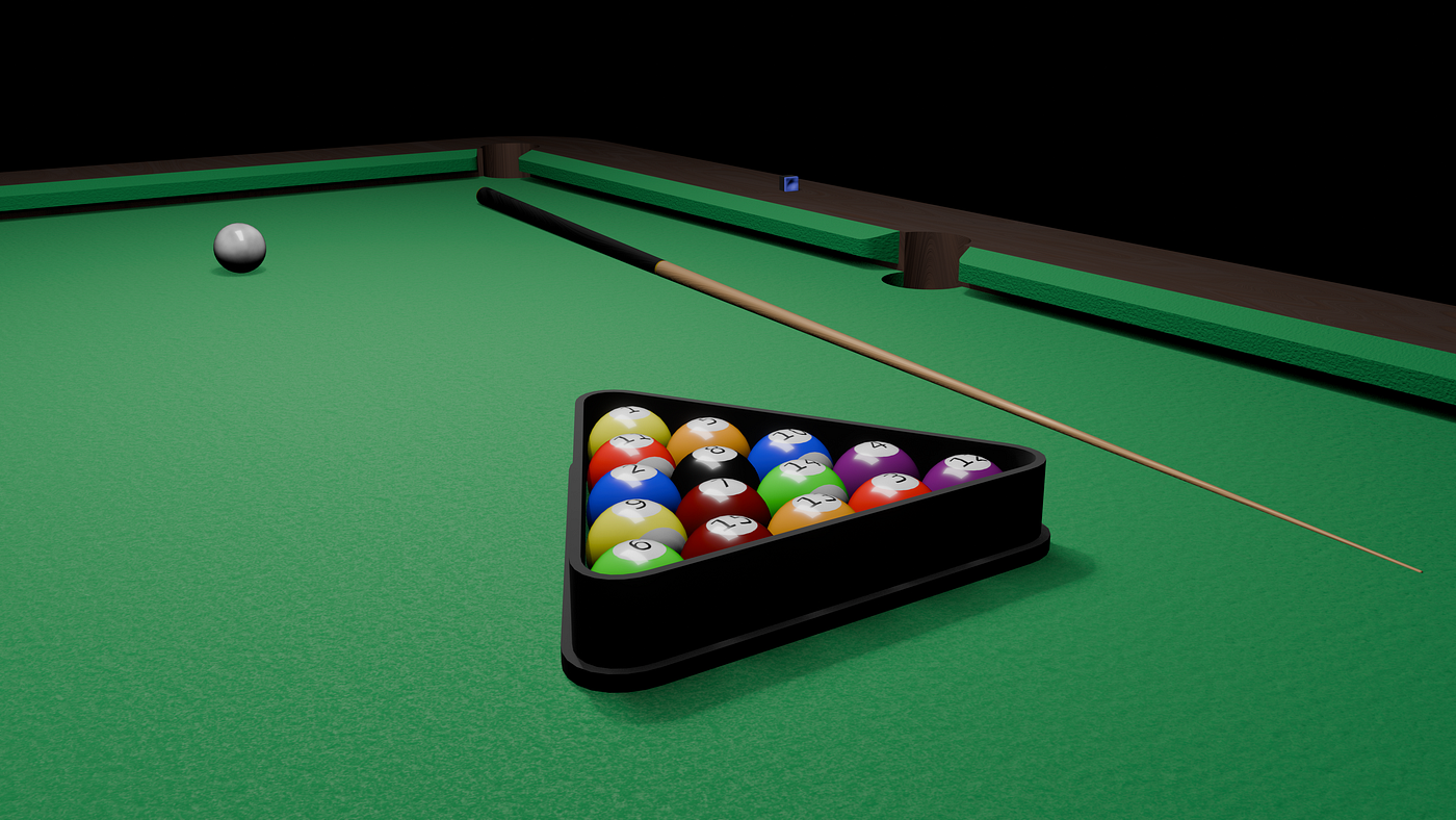
The evolution of specular highlights. Transitioning from the hacks of Phong and Blinn-Phong to the physical rigor of Cook-Torrance. Breaking down the NDF (Beckmann/GGX/Multi-scatter GGX), GSF (Smith/Schlick), and the Fresnel effect.
In the previous part, we modeled the light that penetrates a surface, i.e. the world of diffuse reflectance. Now we move to the light that bounces off the very top layer of a surface before it can enter. Specular reflectance causes the sharp highlights.
We will look at various models which emulated specular highlights. With the empirical shortcuts that powered a decade of real-time graphics, and arriving at the physically rigorous Cook-Torrance microfacet framework that drives every modern engine today.
1. Phong
Phong specular is the original specular model, introduced by Bui Tuong Phong in 1973. It is the baseline that every model after it either builds on or reacts to.
Concept
Phong Specular assumes that a surface acts like a partial mirror. The highlight is brightest when the angle of our eye matches the angle of the reflected light, and fades as we move away from it.

Fig 1: Diagram showing N, L, V, R vectors and the angles ∅ and θ on a surface. Source: GFG - Phong model (Specular Reflection) in Computer Graphics
Where:
- N = Normal vector
- L = Light direction
- V = Viewing direction
- R = Unit vector directed towards the ideal specular reflection
- ∅ = Viewing angle relative to R
- θ = Angle made by L and R with N
For perfect mirrors, ∅ must be 0 to see the reflection. A shiny surface has a narrow specular range, a dull surface has a wider one.
Math
The reflection vector R is:

Eqn 1: Reflection vector calculation.
The specular intensity:

Eqn 2: Phong specular intensity formula.
Where k_s is the specular strength and n is the shininess. High n (e.g. 128) = tiny sharp highlight. Low n (e.g. 4) = broad soft highlight.
To address energy conservation, a normalization factor is applied:

Eqn 3: Energy conservation normalization factor for Phong.
This ensures that as the highlight shrinks, it brightens proportionally, keeping total reflected energy constant.
Advantages And Disadvantages
Pros:
- Extremely cheap to compute, just a dot product and a power function.
- Produces a believable highlight for simple scenes.
Cons:
- As shininess increases, the highlight gets smaller but not brighter. Without the normalization factor, total reflected energy is not conserved.
- Phong highlights are always perfectly circular. It cannot simulate anisotropic surfaces like brushed metal where the highlight stretches into a line.
- At steep grazing angles, the model looks plasticky because it does not account for the Fresnel effect, where surfaces become more mirror-like at the edges.
Implementation
Ambient + Lambert diffuse used alongside Phong specular, same Raylib setup as previous parts.
// specular_phong.fs

float shininess = pow(2.0, (1.0 - roughnessValue) * 8.0);

// ==================== Specular Term (Phong) ====================

float specDot = max(dot(R, V), 0.0);
float specPower = pow(specDot, shininess);

float specularStrength = 0.15;

vec3 specular = vec3(0.0);
if (rawNdotL > 0.0)
{
    float energyConservation = (shininess + 2.0) / (8.0 * PI);
    specular = specularStrength * lightColor * specPower * energyConservation;
}


Fig 2: Phong shading on a torus. The shininess is derived from the roughness value which spans 0 to 1.
2. Blinn-Phong
Also called the Modified Phong Reflection Model, Blinn-Phong is a refinement of Phong that replaces the reflection vector with a more efficient and physically intuitive alternative.
Concept
Rather than computing the dot product of R and V, Blinn-Phong introduces the Halfway Vector H - the vector exactly halfway between the light source (L) and the eye (V).

Eqn 4: The Halfway Vector.
If a tiny mirror existed on the surface and its normal was perfectly aligned with H, it would reflect the light directly into our eye. We measure how close the actual surface normal N is to this perfect orientation H.
Math

Eqn 5: Blinn-Phong specular intensity formula.
The energy conservation factor remains the same as Phong. Because the angle between N and H is always smaller than the angle between V and R, the highlight is naturally wider for the same exponent. To compensate, the shininess mapping uses a slightly higher range of pow(2.0, (1.0 - roughness) 9.0) versus Phong’s 8.0.
Advantages And Disadvantages
Pros:
- In Phong, if the angle between R and V exceeded 90°, the highlight vanished instantly. With Blinn-Phong, N·H can never exceed 90° as long as the light and eye are above the surface, the highlight fades gracefully.
- At steep viewing angles, highlights naturally stretch into an elliptical shape, which looks more realistic than Phong’s perfect circles for materials like wet pavement or brushed metal.
Cons:
- The highlight is naturally larger than Phong’s for the same exponent value, requiring re-tuning of material parameters.
- Like Phong, it is a hack that approximates reality. It does not handle masking where one micro-bump on the surface hides another from the light or the viewer.
Implementation
Ambient + Lambert diffuse used, same Raylib setup as before.
// specular_blinn_phong.fs

float shininess = pow(2.0, (1.0 - roughnessValue) * 9.0);

// ==================== Specular Term (Blinn-Phong) ====================

float NdotH = max(dot(N, H), 0.0);
float specMap = pow(NdotH, shininess);

float specularStrength = 0.15;
vec3 specular = vec3(0.0);

if (rawNdotL > 0.0)
{
    float energyConservation = (shininess + 2.0) / (8.0 * PI);
    specular = specularStrength * lightColor * specMap * energyConservation;
}


Fig 3: Blinn-Phong shading on a torus at varying roughness values.
3. Ashikhmin-Shirley
Ashikhmin-Shirley is a bridge between the empirical Phong world and the physical Cook-Torrance world. It looks like Phong when U = V = 0.5 and metallic = 0 but respects energy conservation and Fresnel.
Concept
Ashikhmin-Shirley’s specular is an anisotropic Phong-style lobe modified with Fresnel. Rather than a single shininess exponent, it uses n_u and n_v. One for each surface direction. This makes it anisotropic by design, not by extension.
- n_u, n_v are Phong-style exponents along the tangent (T) and bitangent (B) directions.
- It has no explicit geometry term. Shadowing and masking are baked into the formulation
- Schlick Fresnel is applied directly to the lobe
The look it produces:
- Low exponents (n_u, n_v < 100): Wide, soft highlights like rough plastic or satin.
- High exponents (n_u, n_v > 1000): Sharp, mirror-like reflections like polished metal.
- Anisotropic (n_u ≠ n_v): Stretched highlights along the tangent or bitangent, like brushed metal or hair.
- Fresnel makes the edges become more mirror-like at grazing angles, just like Cook-Torrance.
Math
The full specular formula is

Eqn 6: Blinn-Phong specular intensity formula.
where p is the anisotropic exponent and F is the Schlick approximation:

Eqn 7: Anisotropic exponent p.

Eqn 8: Schlick’s approximation for Fresnel.
T and B are the tangent and bitangent vectors. The normalization factor ensures energy conservation across all exponent values.
Advantages And Disadvantages
Pros:
- It is intuitive for artists as exponents directly control highlight size
- Handles hair and fabric well due to the tangent-space formulation.
Cons:
- It is empirically fitterd and not derived from a statistical distributions like GGX.
- At very low exponents, the highlight looks blobby rather than having GGX’s characteristic soft tail.
Implementation
Ambient + Ashikhmin-Shirley diffuse used, same Raylib setup. Two roughness sliders (U and V) and a metallic slider.
// specular_ashikhmin_shirley.fs

// Convert roughness to Phong exponents
float n_u = pow(2.0, 13.0 * (1.0 - clamp(roughnessU, 0.01, 0.99)));
float n_v = pow(2.0, 13.0 * (1.0 - clamp(roughnessV, 0.01, 0.99)));

// ==================== Specular Term (Ashikhmin-Shirley) ====================

float p = (n_u * HdotT * HdotT + n_v * HdotB * HdotB) / max(1.0 - (NdotH * NdotH), 0.0001);

float normalization = sqrt((n_u + 1.0) * (n_v + 1.0)) / (8.0 * PI);
float power_term = pow(NdotH, p);
float geometry_term = HdotL * max(NdotL, NdotV);

vec3 F = F0 + (1.0 - F0) * pow(clamp(1.0 - HdotL, 0.0, 1.0), 5.0);

vec3 specular = normalization * (power_term / geometry_term) * F * NdotL * lightColor;


Fig 4: Ashikhmin-Shirley on a torus. Varying roughness U and V independently produces stretched anisotropic highlights.
4. Cook-Torrance
We now move from empirical systems into Physically Based Rendering. Cook-Torrance is a framework. It treats a surface as a collection of millions of tiny microscopic mirrors called microfacets.
- If a surface is smooth, all microfacets point in the same direction as the Normal.
- If a surface is rough, the microfacets point in random directions.
- Only microfacets aligned with the Halfway Vector (H) can reflect light into our eye.
The Cook-Torrance specular equation is:

Eqn 9: The Cook-Torrance specular equation.
D, G, and F are three pluggable functions:
- D : Normal Distribution Function (NDF): What percentage of microfacets are pointing toward H?
- G: Geometry Shadowing Function (GSF): Are microfacets shadowing or masking each other?
- F: Fresnel Function (FF): At this angle, how much light reflects vs. gets absorbed?
Each has multiple implementations. We will go through them one by one.
4.1 D: Normal Distribution Function (NDF)
The NDF answers one question, given a surface with roughness α, what fraction of microfacets have their normal aligned with H? A smooth surface has almost all microfacets aligned. A rough surface has them scattered randomly.
4.1.1 (D) Beckmann
Concept
Beckmann was the original standard NDF. It models microfacet slope distribution as a Gaussian (bell-curve).
Math

Eqn 10: Beckmann NDF.
Where α is roughness and θ_H is the angle between N and H. The roughness α has a physical interpretation:

Eqn 11: Physical interpretation of roughness α, ratio of bump height (σ) to bump width (τ).
In the shader, tan²(θ_H) is computed without trigonometry:

Eqn 12: Efficient tan² computation from dot product.
Advantages And Disadvantages
Pros:
- Physically grounded Gaussian distribution, more honest than Phong/Blinn-Phong.
Cons:
- The highlight falls off too quickly creating a short tail. Real materials have a soft glow around the highlight that Beckmann misses.
- At roughness > 0.6, surfaces look chalky rather than rough-shiny.
Implementation
// D: Beckmann
float alpha2 = max(roughness * roughness, 0.0001);
float NdotH  = max(dot(N, H), 0.0001);
float NdotH2 = NdotH * NdotH;
float tanThetaH2 = (1.0 - NdotH2) / NdotH2;

return exp(-tanThetaH2 / alpha2) / (PI * alpha2 * NdotH2 * NdotH2);
4.1.2 (D) GGX (Trowbridge-Reitz)
Concept
GGX replaced Beckmann as the industry standard. Instead of a Gaussian, it uses a Cauchy (Lorentzian) distribution. It has the same bright center, but with a long soft tail.
Math
The original form:

Eqn 13: GGX NDF original form.
Using tan²(θ_m) = (1 - (N.H)²)/(N.H)² and cos(θ_m) = N.H, it simplified to:

Eqn 14: GGX NDF simplified form.
Advantages And Disadvantages
Pros:
- The long tail produces the natural haze around highlights seen on car paint, brushed metal, and skin. Beckmann cannot replicate this.
- Every modern engine (Unreal, Unity, Blender) uses GGX, so materials and workflows are designed around it.
Cons:
- At very low roughness, the long tail can feel too soft if the goal is a laser-sharp highlight.
Implementation
// D: GGX (Trowbridge-Reitz)
float alpha2  = max(roughness * roughness, 0.0001);
float NdotH   = max(dot(N, H), 0.0001);
float NdotH2  = NdotH * NdotH;
float denomPart = ((alpha2 - 1.0) * NdotH2 + 1.0);

return alpha2 / (PI * denomPart * denomPart);
4.1.3 (D) GGX Anisotropic
Concept
Standard GGX assumes the surface is equally rough in all directions. Anisotropic GGX extends it with two separate roughness values with one per surface direction.
Math

Eqn 15: Anisotropic GGX NDF.
Where T is the tangent (grain direction), B is the bitangent, α_x is roughness along T and α_y is roughness along B. Setting α_x = α_y = α collapses back to isotropic GGX.
Advantages And Disadvantages
Pros:
- The only physically-based way to render brushed metal, hair, satin, and CDs correctly. Without anisotropy, these materials look blobby.
Cons:
- Requires valid tangent and bitangent data. Broken UVs or procedural geometry can produce seams and artifacts.
- Roughly 2–3x more expensive than isotropic GGX.
Implementation
// D: GGX Anisotropic
float aspect = sqrt(1.0 - anisotropy * 0.75);
float alpha_x = max(0.0001, roughness / aspect);
float alpha_y = max(0.0001, roughness * aspect);

float TdotH  = dot(T, H);
float BdotH  = dot(B, H);
float NdotH  = max(dot(N, H), 0.0001);
float NdotH2 = NdotH * NdotH;

float denomPart = (TdotH * TdotH) / (alpha_x * alpha_x)
                + (BdotH * BdotH) / (alpha_y * alpha_y)
                + NdotH2;

return 1.0 / (PI * alpha_x * alpha_y * denomPart * denomPart);
One important limitation: anisotropic shading exposes tangent space discontinuities across triangle edges. Production renderers fix this with MikkTSpace tangent generation. In this implementation, bitangents are derived directly in the vertex shader using the cross product and tangent handedness from vertexTangent.w
// specular_cook_torrance.vs
fragTangent   = normalize(normalMatrix * vertexTangent.xyz);
fragBitangent = cross(fragNormal, fragTangent) * vertexTangent.w;
4.1.4 (D) Multi-scatter GGX
Concept
Standard Cook-Torrance assumes every ray either hits an H-aligned microfacet and reflects to the eye, or misses and is lost forever. On rough surfaces (roughness > 0.5), up to 40% of energy disappears this way, making rough metals look too dark. Multi-scatter fixes this.
A. Heitz (Theoretical Foundation)
Heitz’s approach traces actual light paths through the microfacet height field using Monte Carlo random walks.
Math
Total reflectance is the sum of all bounce orders:

Eqn 16: Heitz multi-scatter, sum of all bounce orders.
Where f_0 is single-scatter Cook-Torrance, f_1 is double-bounce, and so on. The directional albedo:

Eqn 17: Directional albedo integral.
The energy balance:

Eqn 18: Energy balance, single-scatter albedo + missing energy = 1.
E_ss is the energy that escapes on the first bounce. E_ms = 1 − E_ss is the energy lost by single-scatter that needs to come back.
This is stochastic , requires 100–1000+ samples per pixel. It is the theoretical ground truth, not a real-time solution. We use it as the foundation for Kulla-Conty.
Advantages And Disadvantages
Pros:
- Physically exact. The only method that fully solves the multi-scatter problem.
Cons:
- Completely impractical for real-time. Monte Carlo variance produces fireflies without heavy sampling or denoising.
B. Kulla-Conty (Practical Implementation)
Kulla-Conty provides a deterministic, real-time approximation. Instead of tracing paths, it measures the energy lost by single-scatter and redistributes it as a secondary lobe.
The system is built on three values:
- E_ss: Directional albedo: energy reflected by the single-scatter term. For rough surfaces, E_ss < 1.0.
- E_ms = 1 − E_ss: Missing energy to add back.
- F_avg: Average Fresnel, since multi-bounce light reflects at many angles, a hemispherical average is used instead of a single angle-dependent value.
Math
Total BRDF:

Eqn 19: Kulla-Conty total BRDF.
The multi-scatter lobe (full accurate form):

Eqn 20: Kulla-Conty multi-scatter lobe (accurate).
The average Fresnel for Schlick integrates analytically to:

Eqn 21: Hemispherical average Fresnel for Schlick.

Eqn 22: Analytic fit for GGX directional albedo.
For the approximate form, the normalization factor and squared E_ms are linearized for numerical stability:

Eqn 23: Kulla-Conty approximate multi-scatter lobe.
The radiance term has no (N⋅L) factor, this light already failed the geometry term and re-emerges roughly isotropically:

Eqn 24: Multi-scatter radiance, no NdotL term.
Advantages And Disadvantages
Pros:
- It is deterministic with no noise, no fireflies.
- Industry standard: used in Disney Principled BRDF, Unreal Engine 5, and Blender’s Principled BSDF.
Cons:
- The analytic E_ss fit is an approximation. For the most accurate results, a precomputed LUT (keyed on N⋅V and roughness) is required.
- Isotropic only. Anisotropic multi-scatter requires higher-dimensional LUTs and is significantly more complex.
Implementation
// Multi-scatter: Accurate
float r2   = roughness * roughness;
float EssV = 1.0 - (0.15 * r2) / (1.0 + 2.0 * NdotV * (1.0 - r2));
float EssL = 1.0 - (0.15 * r2) / (1.0 + 2.0 * NdotL * (1.0 - r2));
float Eavg = 1.0 - 0.15 * r2;
float EmsV = 1.0 - EssV;
float EmsL = 1.0 - EssL;

vec3 Favg       = F0 + (vec3(1.0) - F0) / 21.0;
vec3 energyTerm = (Favg * Eavg) / (vec3(1.0) - Favg * (1.0 - Eavg));
vec3 f_ms       = (vec3(EmsV * EmsL) / (PI * max(1.0 - Eavg, 0.001))) * energyTerm;
specular       += f_ms * lightColor;

// Multi-scatter: Approximate
float E_ss = 1.0 - 0.28 * roughness * roughness;
float E_ms = 1.0 - E_ss;
vec3 F_avg = F0 + (1.0 - F0) / 21.0;
specular  += E_ms * F_avg * lightColor;
4.2 G: Geometry Shadowing Function (GSF)
The GSF models microfacet self-shadowing and masking. On a rough surface, one microfacet can block light from reaching another (shadowing), or block the eye from seeing it (masking). Without G, rough surfaces are unrealistically bright.
Note: differences between GSF models are subtle on smooth surfaces and become visible at higher roughness values.
4.2.1 (G) Kelemen
Concept
The simplest option. Designed to partially cancel the (N⋅L)(N⋅V) denominator in Cook-Torrance, making it very efficient.
Math

Eqn 25: Kelemen GSF.
Advantages And Disadvantages
Pros:
- Extremely fast. The (N⋅L)(N⋅V) numerator partially cancels with Cook-Torrance’s denominator.
Cons:
- Not roughness-aware. The shadowing curve does not change with roughness, so very rough surfaces look flat.
Implementation
// G: Kelemen
float NdotL = max(dot(N, L), 0.0);
float NdotV = max(dot(N, V), 0.0);
float VdotH = max(dot(V, H), 0.0001);

return (NdotL * NdotV) / (VdotH * VdotH);
4.2.2 (G) Neumann
Concept
Slightly more physically motivated than Kelemen, still cheap.
Math

Eqn 26: Neumann GSF.
Advantages And Disadvantages
Pros:
- Cheap and provides physically-motivated darkening at grazing angles.
Cons:
- Completely roughness-unaware. Smooth and rough surfaces get identical attenuation, which is physically wrong.
Implementation
Our implementation computes G as a separate pluggable function rather than fusing it into the Cook-Torrance denominator, so the cancellation benefit never materializes. The formula just adds extra multiplications with no gain.
// G: Neumann
float NdotL = max(dot(N, L), 0.0);
float NdotV = max(dot(N, V), 0.0);

return min(NdotL, NdotV);
4.2.3 (G) Schlick
Concept
Schlick is a fast rational approximation of Smith-Beckmann, introduced by Christophe Schlick in the same 1994 paper as his Fresnel approximation.
Math
For a single direction X (either L or V):

Eqn 27: Schlick GSF single direction term.
The full geometry term multiplies both directions:

Eqn 28: Full Schlick GSF.
The k remapping is what separates Disney and Epic variants. The original Schlick used k = α√(2/π), which is tied to Beckmann and breaks with GGX. The modern versions:

Eqn 29.1: Disney k re-mappings for direct lighting.

Eqn 29.2: Epic k re-mappings for direct lighting.
Advantages And Disadvantages
Pros:
- Roughness-aware and physically motivated, with no square roots or exponentials.
Cons:
- Treats shadowing and masking as independent (uncorrelated). Height-correlated Smith is more accurate.
Implementation
Epic’s remapping prevents the “black rim” artifact at grazing angles under direct lights. It trades a small theoretical deviation for much more stable results, which is why most engines use it.
// G: Schlick (Disney)
float k    = max(roughness * 0.5, 0.0001);
float NdotL = max(dot(N, L), 0.0);
float NdotV = max(dot(N, V), 0.0);
float G_V  = NdotV / (NdotV * (1.0 - k) + k);
float G_L  = NdotL / (NdotL * (1.0 - k) + k);
return G_V * G_L;

// G: Schlick (Epic)
float k    = pow(roughness + 1.0, 2.0) / 8.0;
// ... same G_V * G_L structure
4.2.4 (G) Smith-Beckmann
Concept
The exact geometry function for Beckmann-distributed surfaces under the Smith microsurface model.
Math
The single-direction masking function:

Eqn 30: Smith G1 masking term.
Where χ+ is the Heaviside function (discards back-facing microfacets), and Λ for Beckmann is:

Eqn 31: Beckmann Λ function.
The full G combines both directions (uncorrelated, separable):

Eqn 32: Separable Smith G2.
Because the full Λ requires erf() and exp(), Walter et al. (2007) derived a rational approximation used in practice:

Eqn 33: Walter’s rational approximation for Beckmann Λ.
Advantages And Disadvantages
Pros:
- Exact solution within the Beckmann statistical framework. Satisfies the Weak White Furnace Test.
Cons:
- Uncorrelated assumption overestimates masking at grazing angles on continuous surfaces.
- Inherits Beckmann’s short-tail look, pairs poorly with GGX NDF.
Implementation
// G: Smith-Beckmann (Walter's approximation)
float sinThetaV  = sqrt(max(1.0 - NdotV * NdotV, 0.0));
float tanThetaV  = sinThetaV / max(NdotV, 0.0001);
float aV         = 1.0 / (alpha * tanThetaV);

float lambdaV = (aV < 1.6)
    ? (1.0 - 1.259 * aV + 0.396 * aV * aV) / (3.535 * aV + 2.181 * aV * aV)
    : 0.0;

float G1_V = NdotV / (1.0 + lambdaV);
// repeat for L, return G1_V * G1_L
4.2.5 (G) Smith-GGX
Concept
Smith-GGX is the height-correlated geometry function for GGX surfaces and the industry standard today. Unlike Beckmann, GGX’s Λ has a closed-form analytic solution, no rational approximation needed.
Math
Height-correlated form (both directions share the denominator):

Eqn 34: Height-correlated Smith-GGX G2.
The GGX Λ function:

Eqn 35: GGX Λ function.
For anisotropic GGX, Λ becomes:

Eqn 36: Anisotropic GGX Λ function.
Where tan(θ_Xx) = (T⋅X)/(N⋅X) and tan(θ_Xy) = (B⋅X)/(N⋅X).
Advantages And Disadvantages
Pros:
- Height-correlated, models that elevated microfacets are more likely to be both visible and lit simultaneously, which is physically accurate.
- Closed-form, no Walter approximation needed. Exact and efficient.
Cons:
- More expensive than Schlick. In practice, engines often use Schlick as a further approximation of this.
Implementation
// G: Smith-GGX (height-correlated)
float alpha2    = alpha * alpha;
float NdotV2    = NdotV * NdotV;
float NdotL2    = NdotL * NdotL;
float tanThetaV2 = (1.0 - NdotV2) / NdotV2;
float tanThetaL2 = (1.0 - NdotL2) / NdotL2;

float lambdaV = (-1.0 + sqrt(1.0 + alpha2 * tanThetaV2)) * 0.5;
float lambdaL = (-1.0 + sqrt(1.0 + alpha2 * tanThetaL2)) * 0.5;

return (NdotV * NdotL) / (1.0 + lambdaV + lambdaL);
4.3 F: Fresnel Function (FF)
Fresnel determines how much light reflects vs. gets absorbed at a given viewing angle. The core observation is that every surface becomes more mirror-like at grazing angles. The difference between models is how accurately and how cheaply can they capture this.
4.3.1 (F) Schlick Approximation
Concept
Already introduced in Part 4 for the Burley diffuse model. The same formula applies here as the specular Fresnel term.
Math

Eqn 37: Schlick Fresnel approximation.
Advantages And Disadvantages
Pros:
- Extremely cheap. Works well for all dielectrics and most artistic metal workflows.
Cons:
- Fails to capture the colored edge shift on metals like gold and copper, it ignores the imaginary part of the refractive index (extinction coefficient κ).
Implementation
F_0 is the base reflectivity at normal incidence. For dielectrics (plastics, wood), F_0 ≈ 0.04. For metals, F_0 is the albedo color itself. The metallic workflow blends between them:
// F: Schlick
float reflectivity = pow((1.0 - ior) / (1.0 + ior), 2.0);
vec3 F0  = mix(vec3(reflectivity), objectColor, metallic);
float VdotH = max(dot(V, H), 0.0);
return F0 + (1.0 - F0) * pow(clamp(1.0 - VdotH, 0.0, 1.0), 5.0);
4.3.2 (F) Full Fresnel: Dielectrics
Concept
The exact Fresnel equation derived from Maxwell’s equations for non-conductive materials (glass, plastic, water).
Math
Reflectance for un-polarized light is the average of s-polarized and p-polarized components:

Eqn 38: Dielectric Fresnel reflectance.

Eqn 39: S-polarized and P-polarized reflectance components.
Where cos(θ) = V⋅H, cos(θ_t) = √[1 − (η_i/η_t)²(1−cos²(θ))] from Snell’s law, η_i = 1.0 (air), and η_t is the material IOR. When sin²(θ_t) ≥ 1, total internal reflection occurs and F = 1.0.
Advantages And Disadvantages
Pros:
- Physically exact for dielectrics. Correctly models total internal reflection and IOR-dependent reflectance curves.
Cons:
- Overkill for real-time. Schlick is within 1–2% error for most cases at a fraction of the cost.
Implementation
// F: Full Fresnel (Dielectrics)
float cosTheta = clamp(dot(V, H), -1.0, 1.0);
// handle entering/exiting medium...
float sinThetaT2 = eta * eta * (1.0 - cosTheta * cosTheta);
if (sinThetaT2 >= 1.0) return vec3(1.0); // Total internal reflection

float cosThetaT = sqrt(1.0 - sinThetaT2);
float Rs = (etaT * cosTheta - etaI * cosThetaT) / (etaT * cosTheta + etaI * cosThetaT);
float Rp = (etaI * cosTheta - etaT * cosThetaT) / (etaI * cosTheta + etaT * cosThetaT);
return vec3(0.5 * (Rs * Rs + Rp * Rp));
4.3.3 (F) Full Fresnel: Conductors
Concept
Metals (conductors) have a complex refractive index n~ = η + i_κ where κ is the extinction coefficient. This absorption is wavelength-dependent, giving metals their characteristic colours.
Math

Eqn 40: Conductor Fresnel equation.
Both η and κ are per-channel (R, G, B) to approximate wavelength dependence. Real-world values (measured at ~550nm):

Table 1: Conductor optical properties. Refractive index (η) and extinction coefficient (κ).
Advantages And Disadvantages
Pros:
- The only way to get physically accurate coloured specular on metals. Gold looks gold, copper looks copper.
- Correctly models the high base reflectance of metals (60–95%) even at normal incidence.
Cons:
- Requires measured η and κ data per metal. Artistic control is limited, you are locked to real-world values or presets.
Implementation
// F: Full Fresnel (Conductors)
float cosTheta  = clamp(dot(V, H), 0.0, 1.0);
float cosTheta2 = cosTheta * cosTheta;

vec3 eta2_kappa2  = eta2 + kappa2;
vec3 numerator    = eta2_kappa2 - 2.0 * eta * cosTheta + cosTheta2;
vec3 denominator  = eta2_kappa2 + 2.0 * eta * cosTheta + cosTheta2;
return numerator / max(denominator, vec3(0.0001));
Cook-Torrance Overall
Advantages And Disadvantages
Pros:
- Physically grounded, energy conservation, Fresnel response, and roughness-dependent behavior all emerge naturally from the framework.
- Modular as D, G, and F can be swapped independently to match different material types or performance budgets.
Cons:
- Significantly heavier than Phong. Three complex functions per pixel instead of one dot product.
- Getting the metallic/diffuse balance right requires understanding the energy conservation terms, getting it wrong produces glowing or plastic-looking results.
Implementation
Ambient + Burley diffuse used. The Cook-Torrance specular is composed by calling D, G, and F as separate pluggable functions and combining them:
// specular_cook_torrance.fs

float D = Distribution(roughness, anisotropy, N, L, V, H, T, B);
float G = Geometry(roughness, anisotropy, N, L, V, H, T, B);
vec3  F = Fresnel(metallic, ior, N, L, V, H, T, B);

vec3 numerator   = D * G * F;
float denominator = 4.0 * NdotL * NdotV;
vec3 specular    = numerator / max(denominator, 0.0001) * NdotL * lightColor;

// Energy conservation
vec3 kS = F;
vec3 kD = (1.0 - kS) * (1.0 - metallic);
vec3 result = ambient + kD * diffuse + specular;
The demo exposes NDF, GSF, Fresnel, and Multi-scatter as dropdown selectors, plus sliders for Roughness, Metallic, IOR, Alpha, and Anisotropy. Full source in lighting_methods/specular_cook_torrance_lighting.

Fig 5: Cook-Torrance on a torus: NDF = GGX, GSF = Smith-GGX, FF = Schlick.

Fig 6: Anisotropic GGX with anisotropy ≈ 0.7, the specular highlight stretches perpendicular to the brush direction, splitting into two thin streaks instead of one circular spot.


Fig 7: Conductor Fresnel presets: Iron, Copper, Gold ...


Fig 8: Multi-scatter comparison at roughness 0.8. Disabled, Approximate, and Accurate. Approximate overshoots brightness; Accurate brightens slightly over Disabled at this roughness.
Conclusion And What’s Next?
We went from Phong’s circular hack to Cook-Torrance’s microfacet framework. We now know that:
- Phong and Blinn-Phong gave us cheap, believable highlights but no physical grounding.
- Ashikhmin-Shirley bridged the gap, anisotropic and energy-conserving without the full D-G-F machinery.
- Cook-Torrance broke specular into three pluggable functions, each with its own family of models, and let us assemble metals, plastics, and brushed surfaces from physically-justified parts.
- Multi-scatter recovered the energy single-scatter throws away at high roughness, fixing the “rough metals look dark” problem.
We now have a complete single-layer BRDF: diffuse and specular both modeled, both energy-conserving, both pluggable.
But real surfaces aren’t single layers. A car has paint under a clear lacquer. Fabric has a sheen that sits on top of its base color. Next, we move into The Extra Layers, where we add a Clearcoat lobe and a Sheen lobe on top of what we’ve built, and look at how multi-layered materials attenuate and interact with the layers beneath them.
메타데이터
- post_id
- e246b0bcb131
- slug
- digital-surfaces-a-deep-dive-into-physically-based-reflectance-part-5-e246b0bcb131
- url
- https://medium.com/@harvarsin/digital-surfaces-a-deep-dive-into-physically-based-reflectance-part-5-e246b0bcb131
- canonical_url
- https://medium.com/@harvarsin/digital-surfaces-a-deep-dive-into-physically-based-reflectance-part-5-e246b0bcb131
- author_url
- https://medium.com/@harvarsin
- status
- ok
- fetched_at
- 2026-06-24 23:31:39