Troubleshooting a 24/7 Dash Cam Setup in a Jeep JKU
Assembling custom computer hardware teaches you that the cleanest blueprint rarely survives first contact with physical gear.
Troubleshooting a 24/7 Dash Cam Setup in a Jeep JKU
Assembling custom computer hardware teaches you that the cleanest blueprint rarely survives first contact with physical gear.
Wiring a 24-hour monitoring dash cam into a Jeep JKU seems simple: automate it to run constantly while parked, switch to standard recording when driving, and keep it hands-off without a physical switch panel.
The initial plan relied on an 8-circuit sPOD Source SE for clean power distribution and battery protection. Instead, it became a lesson in debugging software logic and electrical behavior.
The Components & Physical Routing
A 24/7 parking setup requires a three-wire hardwire kit to deliver two distinct signals to the camera:
- Ground (Black Wire): Electrical return path.
- Constant 12V (Yellow Wire): Direct battery link for low-power background recording while parked.
- ACC/Switched 12V (Red Wire): Ignition line that signals the camera to switch between parking and driving modes.
Clean cable management is a direct reflection of workmanship. I routed the main harness from the rearview mirror, tucked it cleanly behind the plastic interior trim along the windshield header and down the driver’s side A-pillar, then passed it safely through the factory firewall grommet to protect it from pinch points and engine heat.
Phase 1: The sPOD Bottleneck
The physical install was clean. Wires ran from the rearview mirror, down the driver’s side plastic trim, and through the firewall foam grommet. Ground went to the chassis, constant yellow to Circuit 1 (SW1), and switched red to Circuit 2 (SW2).
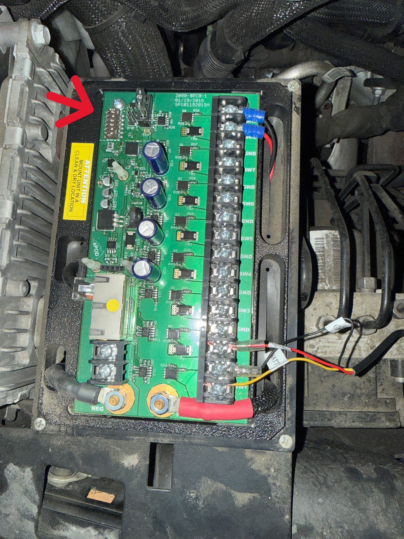
Uncovered sPOD board showing wires running to the terminal strips and arrow showing switch panel
To bypass a switch panel and automate execution, I set internal sPOD DIP switches #1 and #2 to ON so the board would read external voltage signals. Then I ran an 18AWG trigger wire from an ignition-switched fuse slot to the sPOD input terminal.
The Diagnostic Failure
During testing, the outputs refused to send power, registering a locked-out 0.26V on the multimeter.
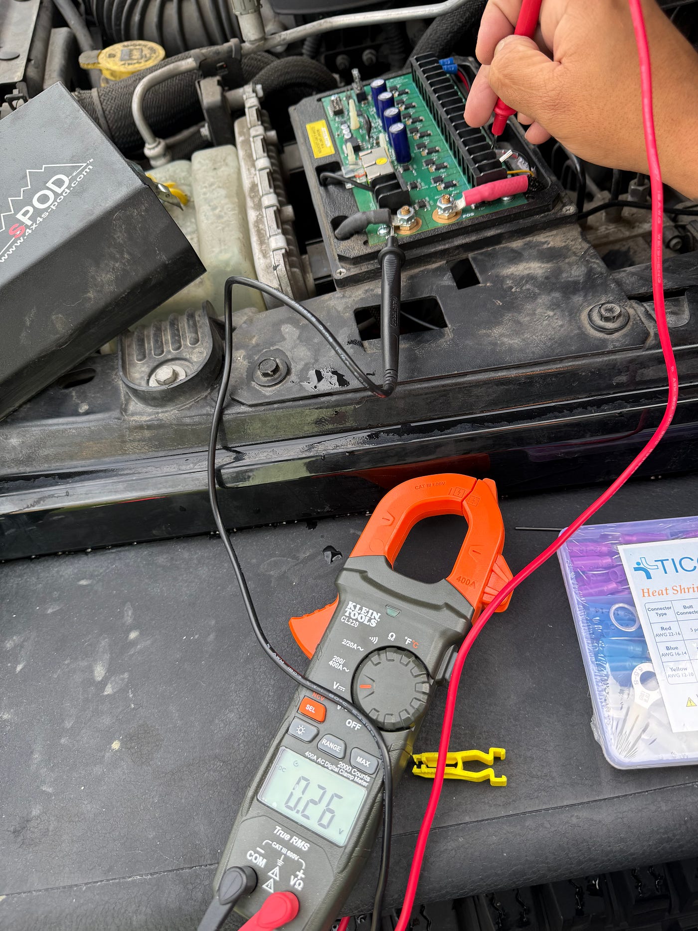
Multimeter displaying 0.26V with the test probes on the accessory board
The sPOD SE uses a protective digital loop: if it detects low voltage, it clamps down and locks out circuits. To reset, it requires a clear alternator charging signal above 12.8V.
Even with the engine running and pulling 14V at the battery, operating without an integrated hardware switch panel prevented the digital brain from parsing the changes between the constant and switched lines. The safety programming locked the unit in a sleep cycle.
Phase 2: Moving Directly to the Fuse Box
When a digital control box introduces too much software abstraction for a simple binary task, strip away the layers and return to direct physical routing. I bypassed the sPOD entirely and moved the wiring directly to the main Jeep TIPM fuse box.
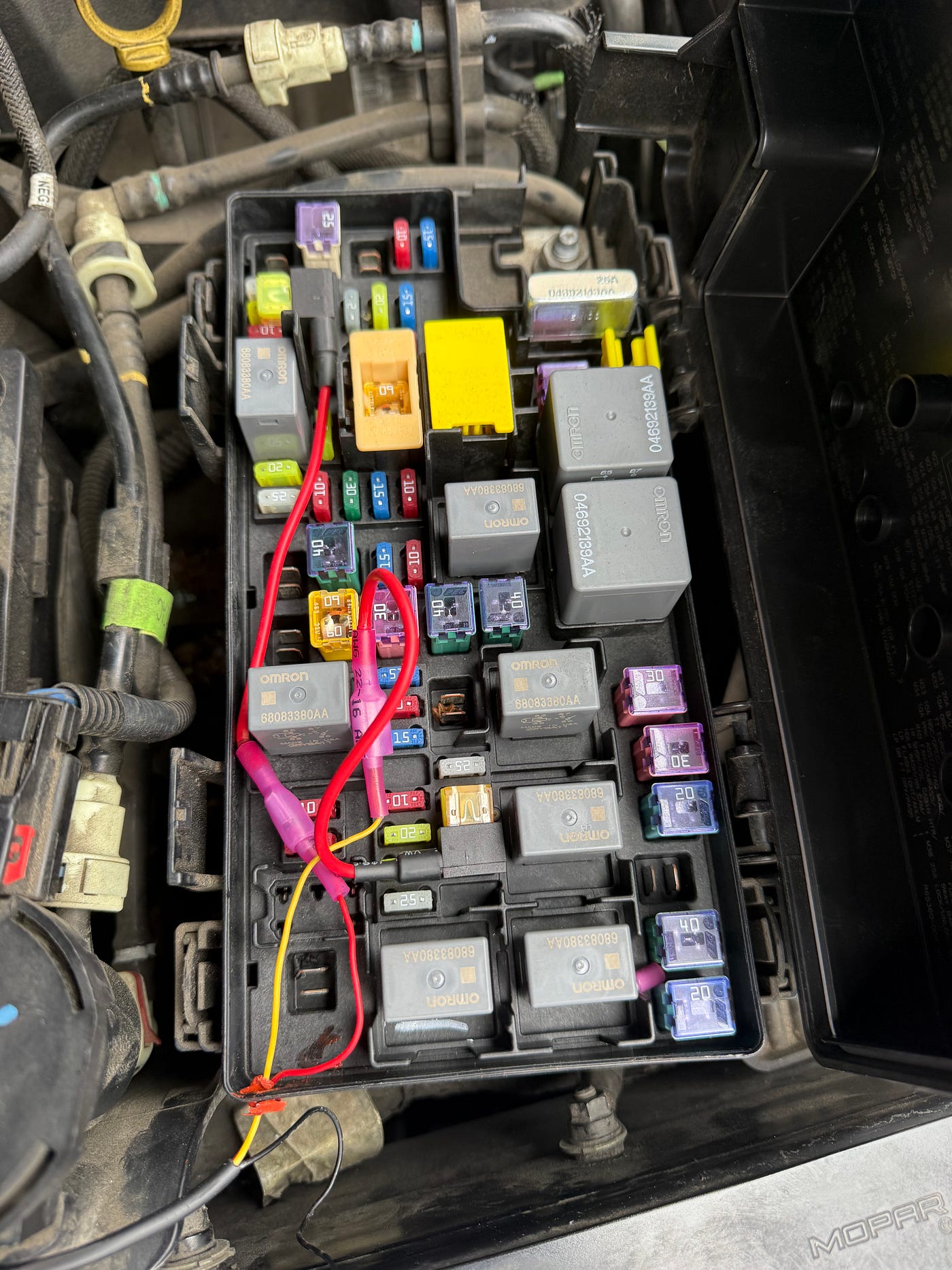
Top-down view of the engine bay fuse box with the taps installed
The Strategy:
- Isolate the Signals: Split the dash cam’s inline voltage module away from the accessory board.
- Tap Fuse M7 (Switched Signal): Used an Add-a-Fuse tap on Fuse M7 (rear power outlet). The JKU fuse slot has three pins, letting you slide the fuse left or right to toggle between “Always On” and “Key-Switched.” I selected the key-switched side for the engine status signal.
- Tap the Constant Source: Routed the constant line into a verified unswitched slot for an unbroken, 24/7 path straight to the battery.
Oops!
The JKU fuse box features a specific mechanical design for this slot: it has three pin holes instead of two. This configuration allows you to slide the fuse tap into two different physical orientations, one bridges to a “Key-Switched” circuit, while the other hooks into an “Always On” battery feed.
During the initial routing, I accidentally pushed the tap into the “Always On” side. This tiny alignment error kept the red signal wire hot 24/7, preventing the camera from entering its low-power sleep mode and effectively killing my battery overnight. Once I pulled the tap and shifted it over to the correct key-switched position, everything finally worked exactly like it was supposed to.
I was able to drill a small entry hole on the side of the box, fed the wires through, and to weatherproof it sealed it up with heat resistance sealant to lock down the install.
Verification & Risk Mitigation
Bypassing a smart accessory hub like the sPOD meant taking direct responsibility for hardware risk management. To ensure low-voltage protection and prevent a dead battery in the field, I utilized a professional-grade hardwire kit featuring an integrated voltage cutoff module set to a strict threshold.
To validate the deployment, I ran a systematic testing protocol using the inline digital display:
- Engine Off: Confirmed the constant line maintained steady battery voltage while the switched line dropped to 0V. The display correctly went dark on the trigger line, successfully shifting the camera lens loop into its low-power “Parking Mode.”
- Engine Cranking: Confirmed the switched line instantly jumped to alternator voltage (~14V), signaling the camera to cleanly boot out of surveillance and into active driving mode.
The Verdict
Shifting to a dedicated hardware-fused setup delivered complete automation.
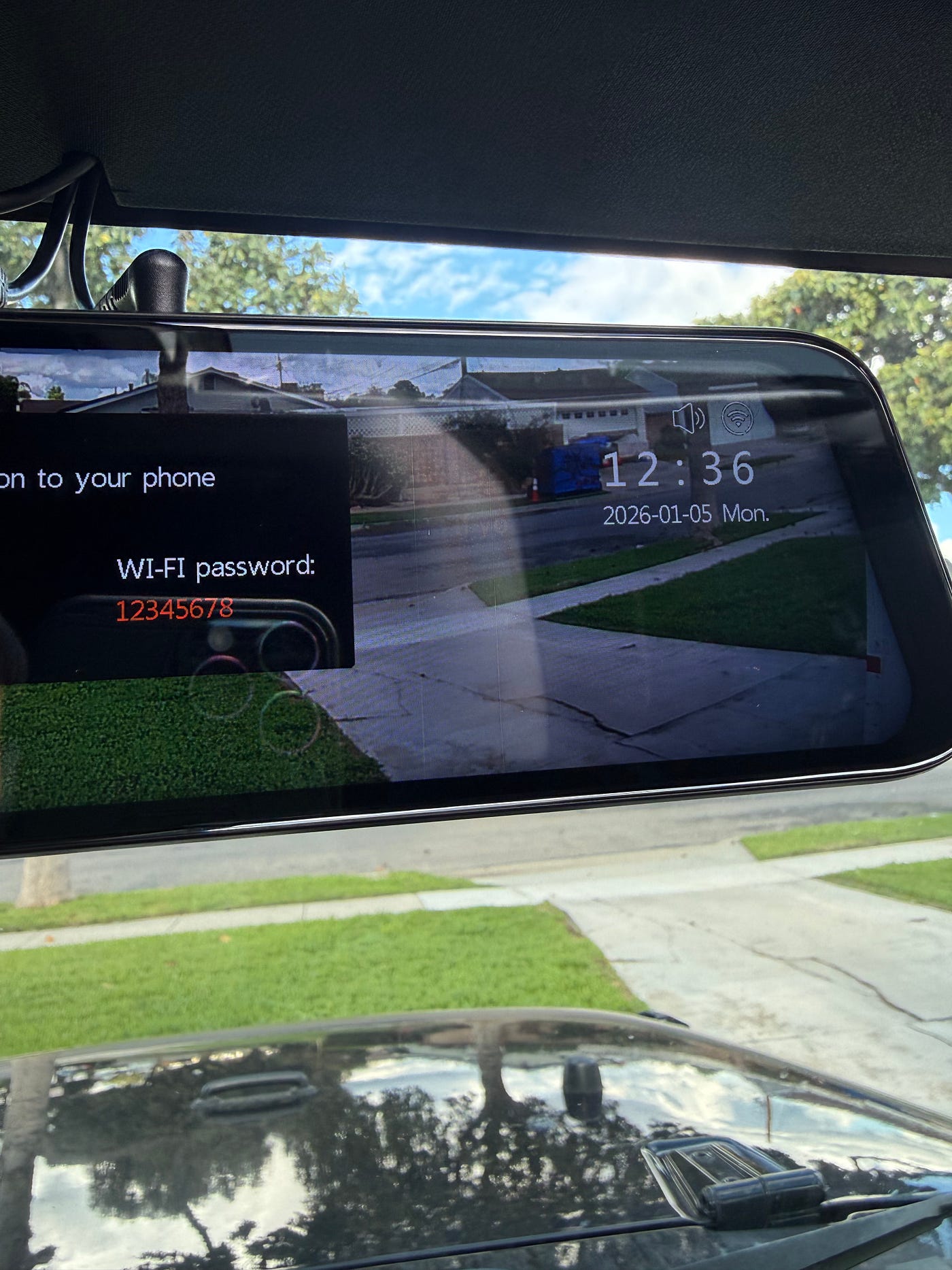
Shifting to a dedicated hardware-fused setup delivered complete automation.
The second the key turns, the M7 circuit goes hot, the voltage regulator wakes up, and the camera records driving footage. Turn the key off, the dropped signal flags the camera to switch to low-power parking surveillance, and the inline regulator monitors battery levels so the engine cranks perfectly every morning.
Bypassing a high-end digital controller for a direct, clear physical path is often the fastest way to get a reliable result.
메타데이터
- post_id
- e4fc2d0645fc
- slug
- troubleshooting-a-24-7-dash-cam-setup-in-a-jeep-jku-e4fc2d0645fc
- url
- https://medium.com/@flogood/troubleshooting-a-24-7-dash-cam-setup-in-a-jeep-jku-e4fc2d0645fc
- canonical_url
- https://medium.com/@flogood/troubleshooting-a-24-7-dash-cam-setup-in-a-jeep-jku-e4fc2d0645fc
- author_url
- https://medium.com/@flogood
- status
- ok
- fetched_at
- 2026-06-13 16:00:06