GPU-Accelerated Effects: Glitch at Scale
A few weeks ago I saw a great article by Sina Samaki about making a glitch effect using compose. As someone who enjoys doing low level…
GPU-Accelerated Effects: Glitch at Scale
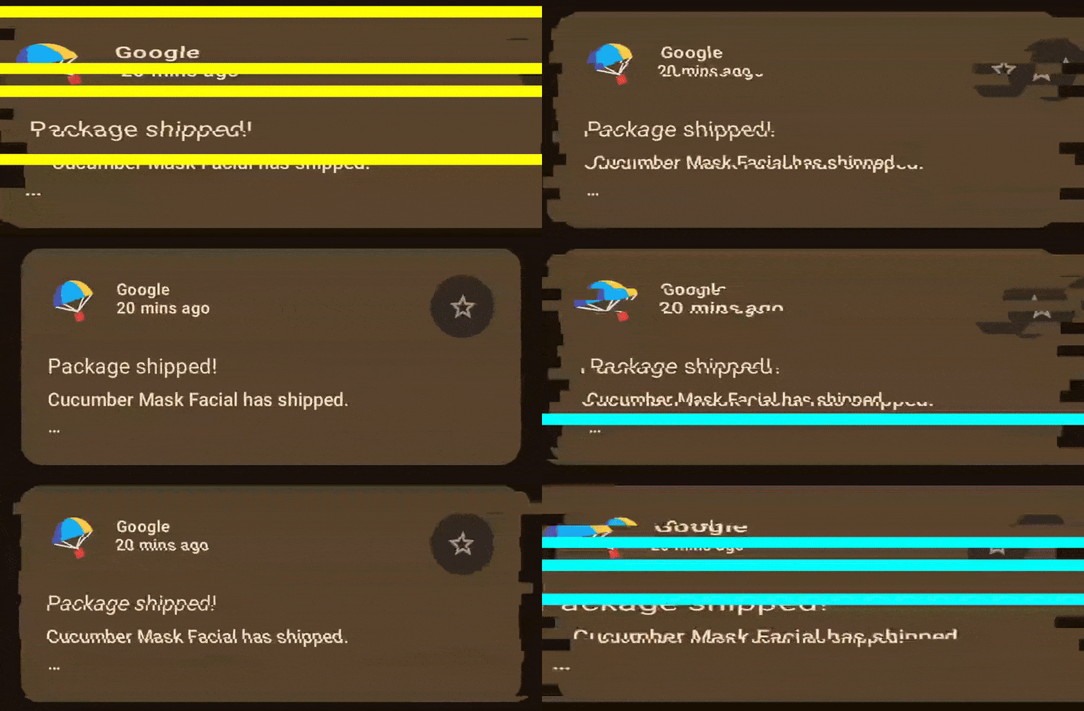
A few weeks ago I saw a great article by Sina Samaki about making a glitch effect using compose. As someone who enjoys doing low level things I saw a good opportunity to recreate this effect using Android AGSL shaders and compare the implementations.
When it comes to graphics, it’s quite important to choose the right tool for the job, because it’s very easy to hit the performance ceiling and hard to scale the solution. Is it the case here? Let’s see!
Brace yourselves, we are going to do lower level things.
The nature of shaders
So, what are shaders in the first place? A shader is a program that is executed directly on the GPU, and executed in parallel. Shaders are usually written in a special C-alike language, in case of Compose on Android it is AGSL — Android Graphics Shading Language.
I’m not going to repeat the good official guide, but instead I’ll talk a bit about the GPU and a new mental model for shader programming.
So, what is the difference with the CPU? The key difference between CPU and GPU is basically this:
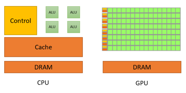
https://developer.nvidia.com/blog/cuda-refresher-reviewing-the-origins-of-gpu-computing/
CPU:
- More sophisticated
- Designed for larger programs that do a lot of different tasks
- MIMD (Multiple Instruction — Multiple Data)
GPU:
- Much simpler (No branch prediction, smaller caches)
- Designed for small programs that do exactly the same operations over various data
- More cores = higher parallelism
- SIMD (Single Instruction — Multiple Data)
Of course, CPUs have SIMD extensions, but not at the same scale as GPU.
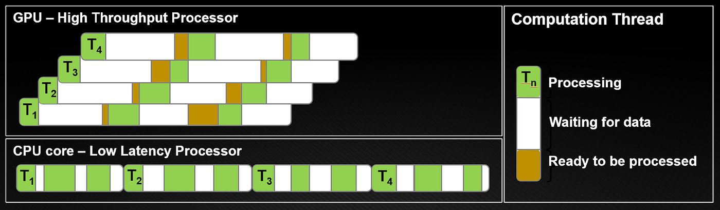
https://developer.nvidia.com/blog/cuda-refresher-reviewing-the-origins-of-gpu-computing/
GPU is great for performing the same operation over millions of pixels
There is a very important mental model shift: instead of having a canvas where you can draw at any place, now you have an image that you can sample (read) any part, but the output would be a single pixel. The same shader is executed for every target pixel. It is similar to a pure function in a way that no side effects are possible, so a pixel depends only on its coordinates and uniforms that were provided.
Let’s go to the implementation, but first, analyze the key points in the original compose version and translate those ideas to a shader mental model.
The key animation driver is step. Animatable counts float values from 10 down to 0 over 500 ms period. The step state is integer and as a float is converted to int, there are 11 steps.
var step by remember { mutableStateOf(0) }
LaunchedEffect(key) {
   Animatable(10f)
       .animateTo(
           targetValue = 0f,
           animationSpec = tween(
               durationMillis = 500,
               easing = LinearEasing,
           )
       ) {
           step = this.value.roundToInt()
       }
}
Then there is an additional parameter called intensity that is calculated based on step:
val intensity = step / 10fThus intensity is a series of numbers [1.0, 0.9, …, 0.0].
The next key point is slicing:
for (i in 0 until slices) {
    translate(
        left = if (Random.nextInt(5) < step)
            Random.nextInt(-20..20).toFloat() * intensity
        else
            0f,
    ) {
        scale(
            scaleY = 1f,
            scaleX = if (Random.nextInt(10) < step)
                1f + (1f * Random.nextFloat() * intensity)
            else
                1f,
        ) {
            clipRect(
                top = (i / slices.toFloat()) * size.height,
                bottom = (((i + 1) / slices.toFloat()) * size.height) + 1f,
            ) {
                layer {
                    drawLayer(graphicsLayer)
                    if (Random.nextInt(5, 30) < step) {
                        drawRect(
                            color = glitchColors.random(),
                            blendMode = BlendMode.SrcAtop,
                        )
                    }
                }
            }
        }
    }
}
For every slice the following transformations are applied:
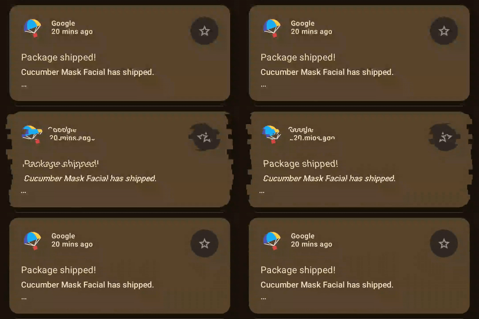
1. Translation
- During steps 10 to 5 each slice is moved by a random amount of pixels in range -20..20. Note that with every step this range gets reduced as it is multiplied by intensity
- During steps 4 to 0 happens a similar thing, but it is not guaranteed for every slice, some slices will not be moved
I often use compose samples Reply demo to have a look of a real app
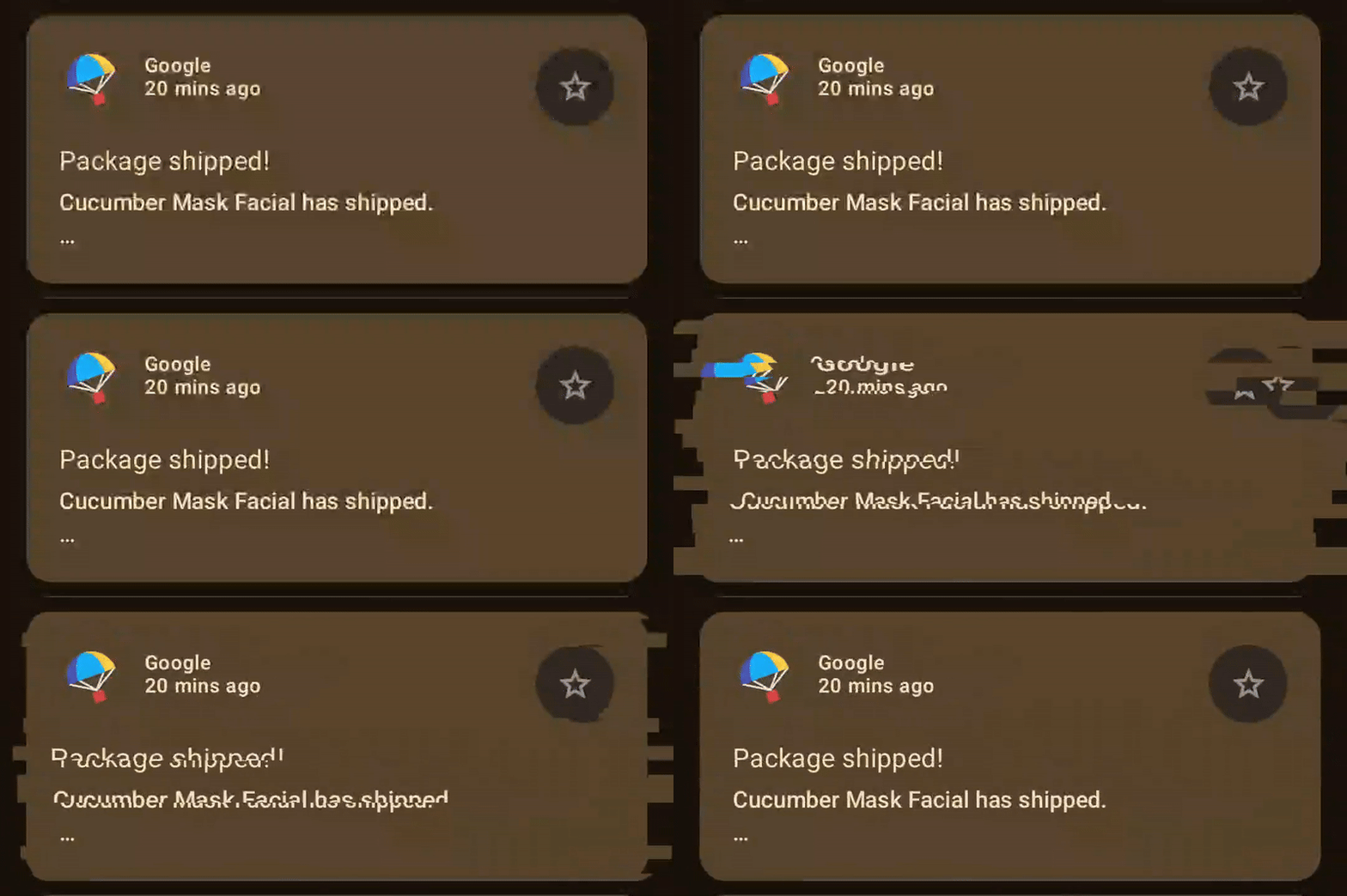
2. Horizontal scale Every slice is being scaled up by a random number in range 1.0..2.0 depending on intensity, reducing probability and size with every step
3. Coloured stripes
- During steps 10 to 5 draw a randomly coloured stripe on each slice with initial probability of 0.2 reducing to 0 by step 5.
- No stripes after step 5
So, overall, the animation is the most expressive on the first steps and creates the effect of settling down during the second half.
For the shader intensity should be enough to drive the animation without using steps. In the Kotlin code I will still rely on steps + intensity just for the sake of replicating the animation as close as possible and for the future performance measurements.
Mental model shift: shaders are executed in a per-pixel manner, BUT animation applies the same transformations to the groups of pixels — slices in this case. To be able to replicate that in a shader we need to do exactly the same calculations for the whole slice. Remember similitude with pure functions? It’s very handy here, because to get the same results we simply need to apply the same arguments!
The group of pixels that share the same transformations is a slice:
uniform shader image;
uniform float2 imageSize; // Shader area size in pixels
uniform float intensity;
uniform int slices;

// fragCoord — pixel coordinates
half4 main(float2 fragCoord) {
    // Create horizontal slices
    float sliceHeight = imageSize.y / float(slices); // Height of each slice in pixels
    float sliceY = floor(fragCoord.y / sliceHeight) * sliceHeight; // Start coordinates for each slice

    // ...
}
Let’s go step by step and start with translation.
Translation
Steps 10..5 are equivalent to intensity 1.0..0.5 with 0.1 decrement. So for shifting the slices we shall rely on that:
// Simple random functions
float random(float seed) {
  return fract(sin(seed) * 100000.0);
}

float random(float2 st) {
    return fract(sin(dot(st.xy, float2(12.9898, 78.233))) * 43758.5453123);
}

// Determine how much this slice should be displaced
float displace(float sliceY, float intensity) {
    float rnd = random(float2(sliceY, intensity));

    float shouldDisplace;
    if (intensity < 0.5 && intensity > rnd * 0.4) {
        shouldDisplace = 0.0;
    } else {
        shouldDisplace = 1.0;
    }

    return (rnd - 0.5) * 40.0 * intensity * shouldDisplace
}
What happens here? Firstly, random. Since there is no randomness in shaders, there are commonly used functions that simulate randomness. Both functions return a float value between 0 (inclusive) and 1 (exclusive). In this case the “random” value is something unique for every slice-frame combination. A uniform intensity is the same for all the invocations (= output pixels) for every given frame, the slice coordinates are also the same for the same group of pixels. Combined with the slice start coordinate this value is different for each slice on each frame.
Next, if intensity is over 0.5 shouldDisplace factor is instantly set to 1.0 meaning that the slice has to be displaced. Otherwise, intensity > rnd * 0.4 results in a declining probability of performing displacement similar to Random.nextInt(5) < step in the original implementation.
The last line is just simple arithmetics. Here I’m converting 0..1 pseudorandom value to -20..20, multiplying by intensity just like in the original implementation and applying the factor if displacement takes place at all.
I often use compose samples Reply demo to have a look of a real app
Scaling
Scaling in screen space basically means adjusting pixel sampling coordinates relative to a pivot point, horizontal center in this case. Since we’re reading from the source image, we effectively move the sampling viewport.
float2 scale(float2 coord, float yMin, float yMax, float screenWidth, float intensity) {
   float rnd = random(float2(yMin, intensity));

   if (coord.y >= yMin && coord.y <= yMax && rnd < intensity) {
       float centerX = screenWidth * 0.5;

       float localX = coord.x - centerX;
       float scaleFactor = 1f + (intensity * rnd);
       localX /= scaleFactor;

       float scaledX = localX + centerX;

       return float2(scaledX, coord.y);
   }

   return coord;
}
Sidenote: I’m trying to keep the logic as simple as possible for the demonstrational purposes. Production shader code usually uses more advanced techniques to avoid branching, because imbalanced branching like on the sample above forces GPUs to execute both paths serially, killing parallelism. It’s not straightforward to implement a scaling function in an optimized way, so I’m following a naive approach.
Again, random is unique for every slice for every frame, which means that every pixel in a particular slice gets the same value. Then rnd < intensity results in reducing probability similar to Random.nextInt(10) < step.
Coloured stripes
The simplest part. Similarly, create the same probability if the colour band is applied, and then select one of the 3 colours. It’s possible to use non-hardcoded values but requires some additional work, so the Compose version is more flexible in this sense.
float rnd = random(float2(intensity, sliceY));
if ((rnd * 2.5 + 0.5) < intensity) {
   if (rnd > 0.67) {
       return yellow;
   } else if (rnd > 0.33) {
       return red;
   } else {
       return cyan;
   }
} else {
   float2 scaled = scale(displaced, sliceY, sliceY + sliceHeight, imageSize.y, intensity);
   return image.eval(scaled);
}
After putting everything together here’s the result:
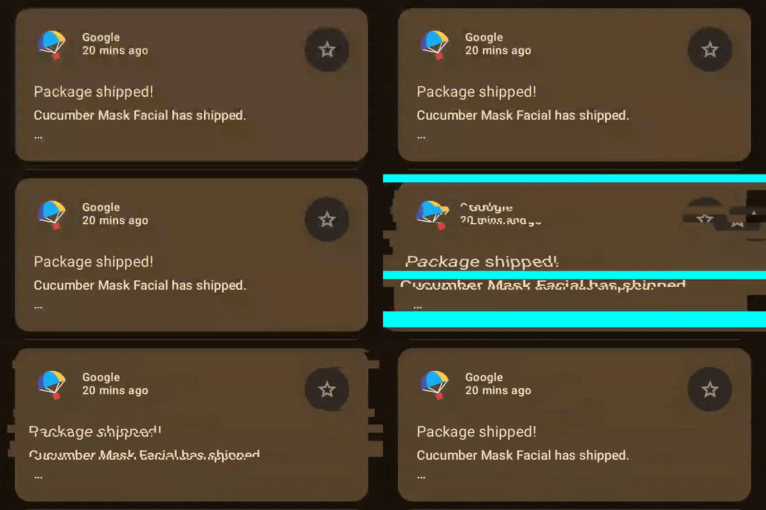
There is an obvious problem: the overlay colour is always cyan. It happens because the pseudo-random function returns the same value for the same inputs — deterministic by design. Solution: generate true randomness on the Kotlin side and pass it as a uniform.
-float rnd = random(float2(intensity, sliceY));
+float rnd = random(float2(intensity * realRandom, sliceY));
 if ((rnd * 2.5 + 0.5) < intensity) {
-    if (rnd > 0.67) {
+    if (realRandom > 0.67) {
         return yellow;
-    } else if (rnd > 0.33) {
+    } else if (realRandom > 0.33) {
         return red;
     } else {
         return cyan;
     }
} else {
    float2 scaled = scale(displaced, sliceY, sliceY + sliceHeight, imageSize.y, intensity);
    return image.eval(scaled);
}
After applying proper randomness, the whole thing replicates the original behavior very closely:

Can you guess which is compose and which is AGSL?
The full code is published here.
Of course, when it comes to graphics programming, at least some rough performance observations need to be done. For that purpose I’ll take my Pixel 7, enable HWUI rendering charts, and slightly change the code: loop animation using infiniteRepeatable spec and will use a release build. Pixel 7 is actually quite good for that task, because it is not a high-end device by any means and if it works on Pixel 7 then it will work on more performant devices too.
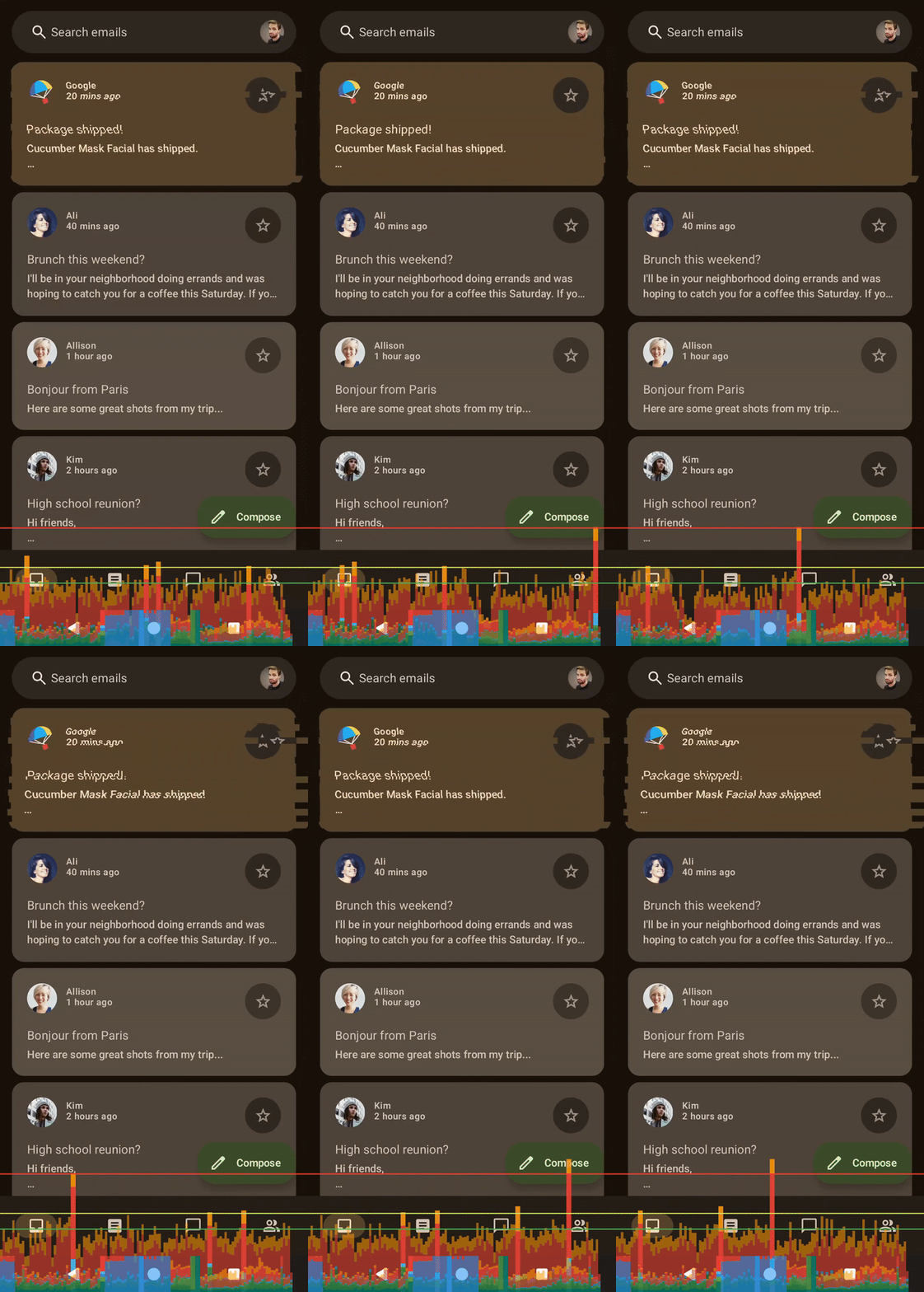
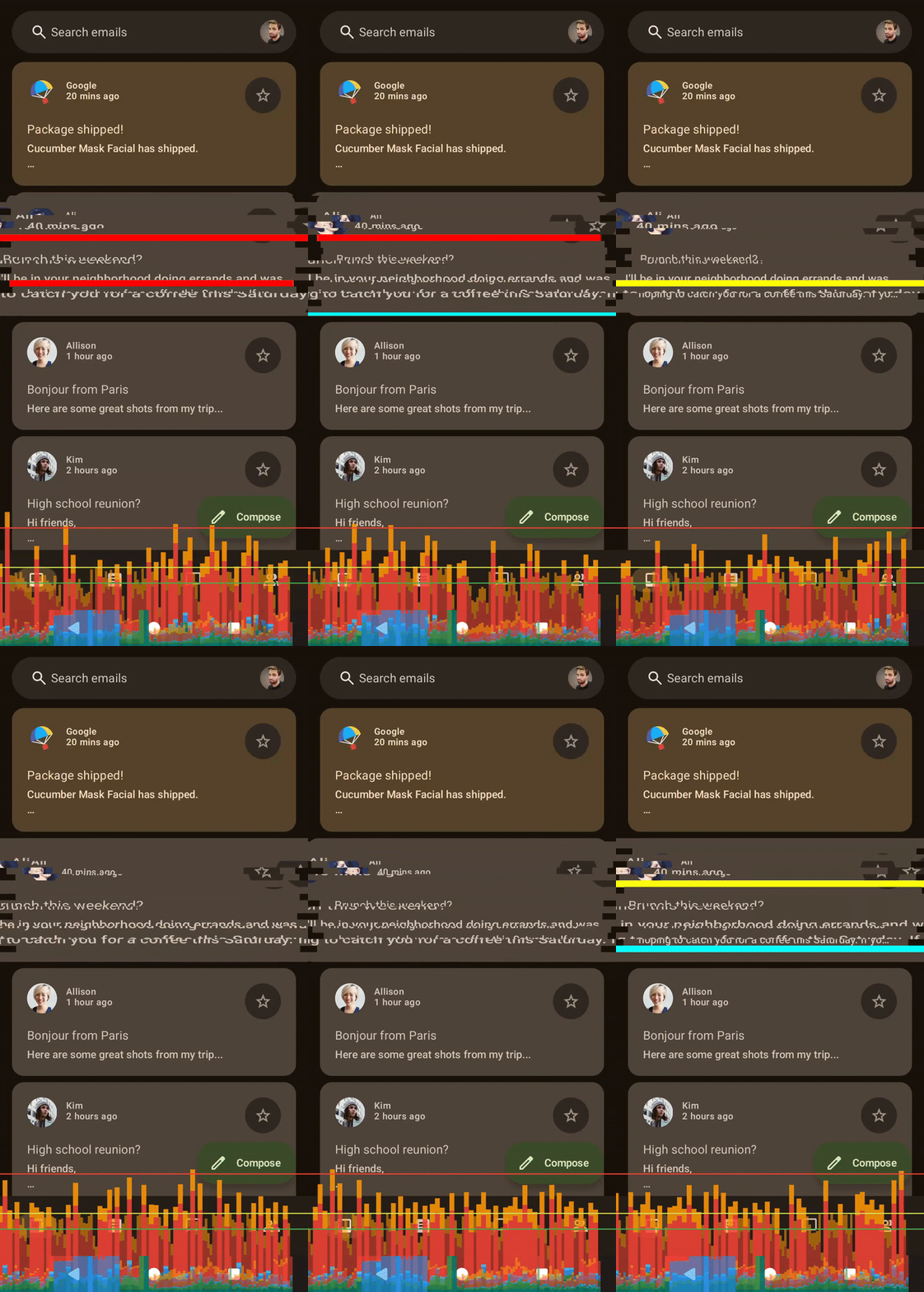
Shader left, compose right
The charts look similar at first glance, but there’s a catch: current implementation implicitly limits frame rate. The animation counts float values down from 10 to 0, but state is updated with values rounded to integer. It means that there are just 11 frames of animation over 500ms. It’s very convenient for a glitch shader, because lower framerate also contributes to the glitchiness perception. To remove this limitation we just need to change the step type from Int to Float and use animatable value without rounding.
-var step by remember { mutableStateOf(0) }
+var step by remember { mutableFloatStateOf(0f) }
LaunchedEffect(key) {
   Animatable(10f)
       .animateTo(
           targetValue = 0f,
           animationSpec = tween(
               durationMillis = 500,
               easing = LinearEasing,
           )
       ) {
-           step = this.value.roundToInt()
+           step = this.value
       }
}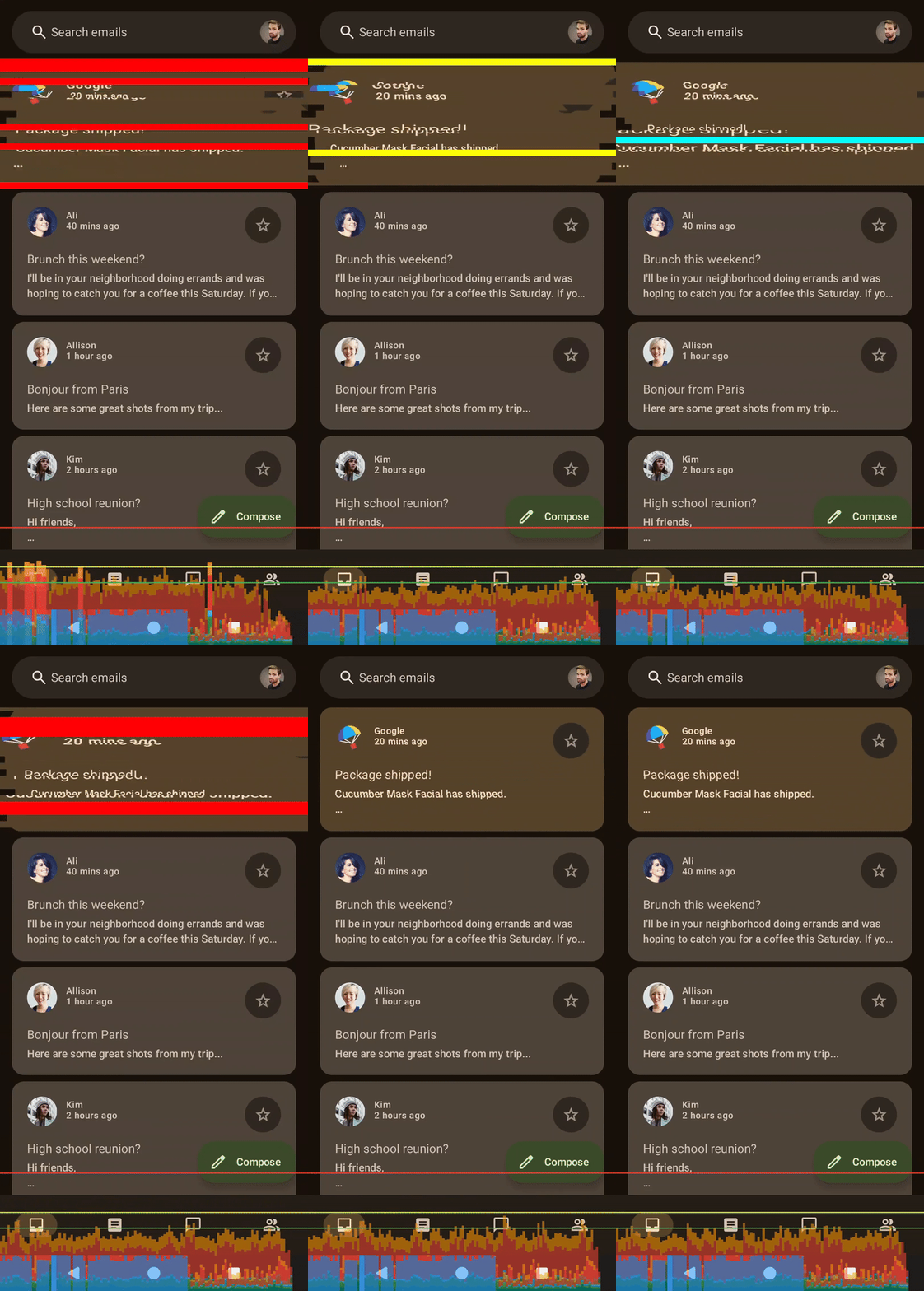
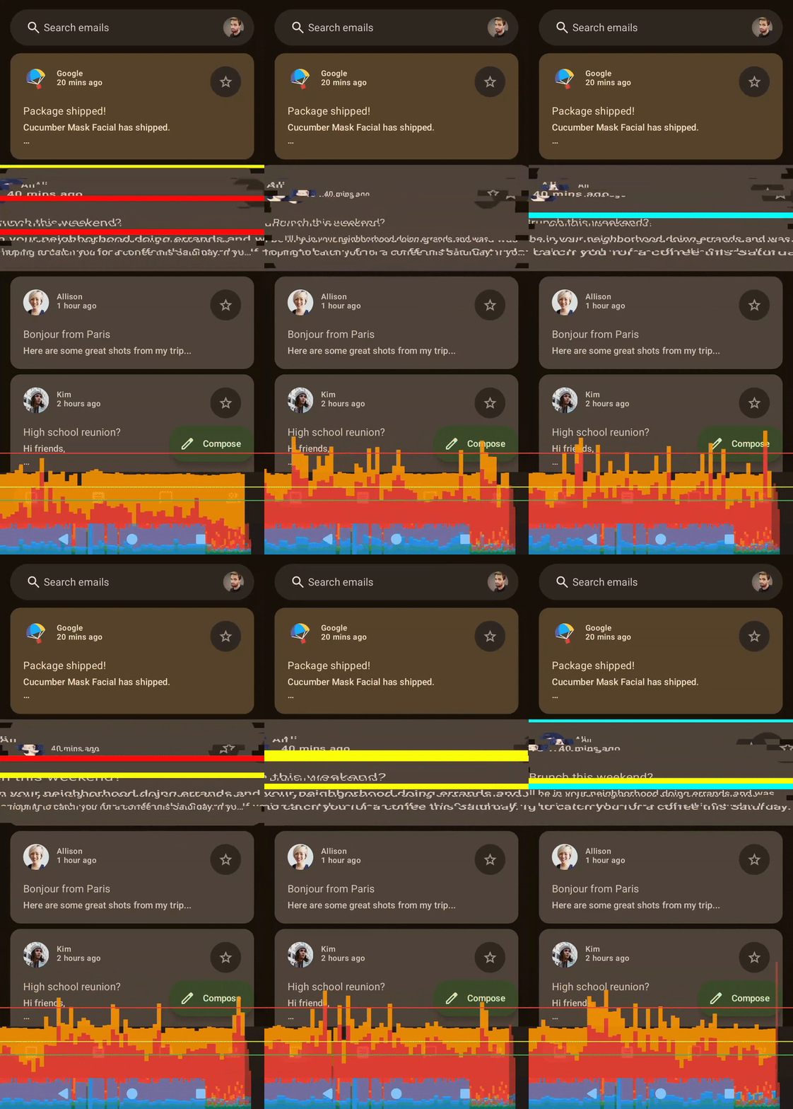
Shader left, compose right, no frame limit
With the removed frame limit the performance gap is already noticeable. Let’s make a stress-test. What happens if the animation is applied to the whole list? Or the number of slices grows? Let’s see!

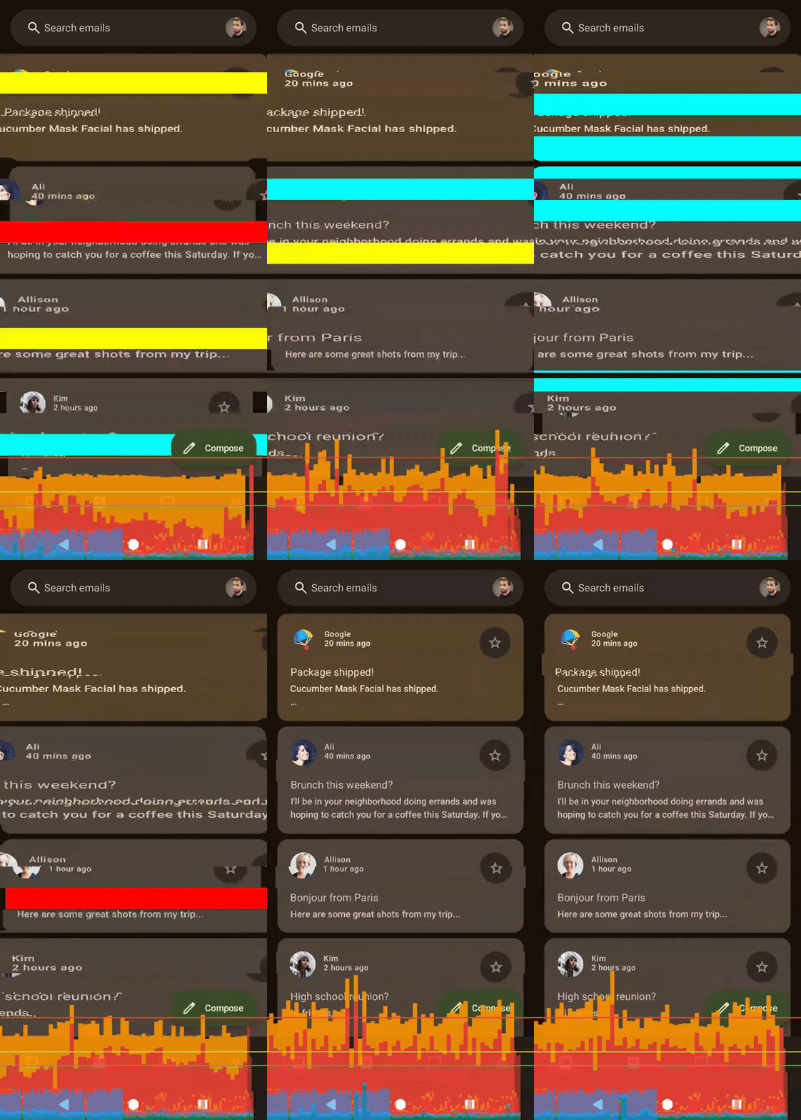
Shader left, compose right, no frame limit, applied to whole list

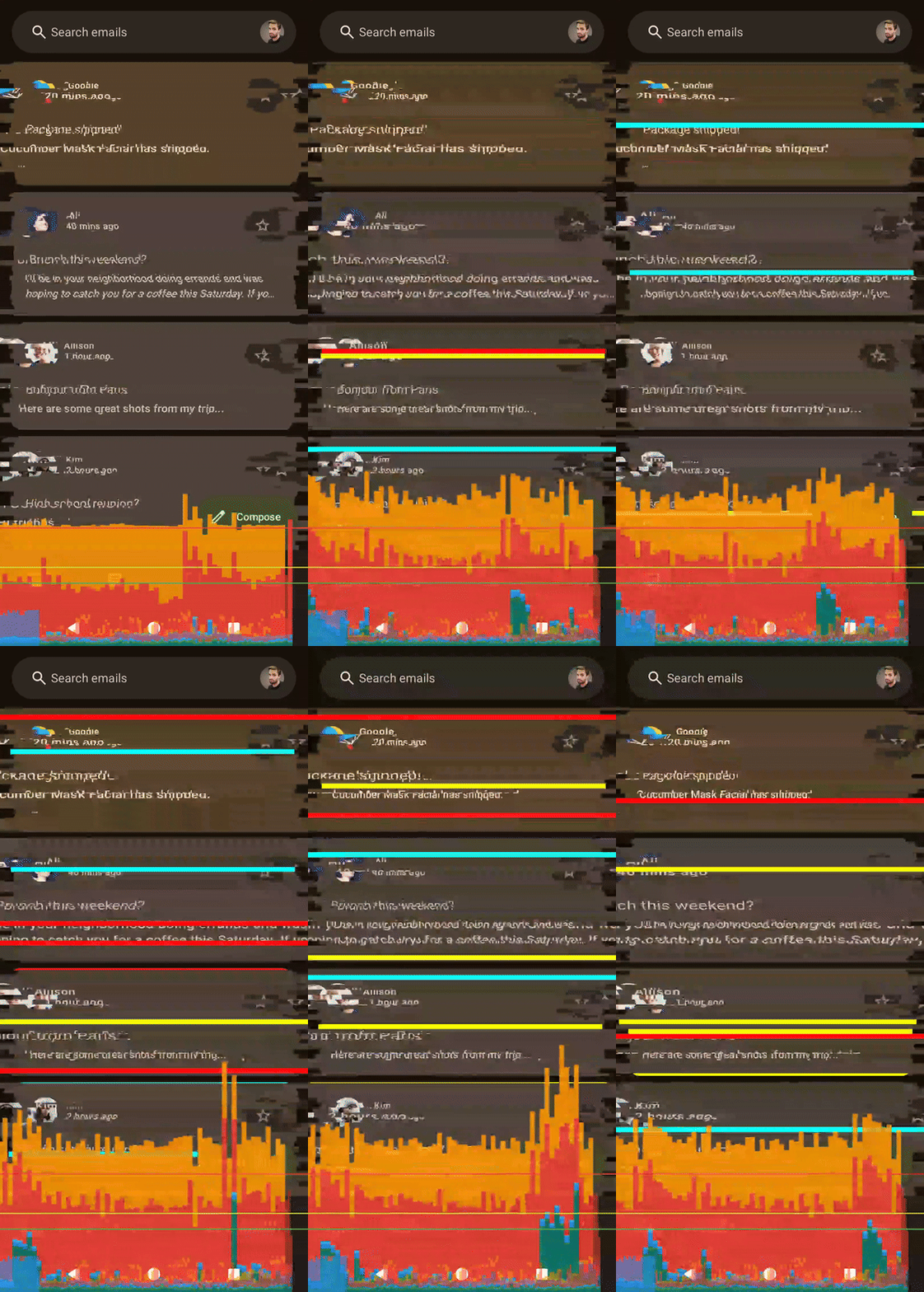
Shader left, compose right, no frame limit, applied to whole list, 100 slices
Conclusion
Compose is very good for prototyping complex animations because it is easy to implement such things with familiar tools. Also, it’s important to mention that it will work on all devices.
On the other hand, shaders offer substantially more performant and stable rendering. In this particular case it doesn’t matter, how many slices are used — computationally there is no difference if it is 20 or 500, while pure compose version is very sensitive in this matter and grows linearly when slices count increases. Additionally, since AGSL shader is just text that is compiled ad-hoc at the runtime, technically it’s possible to update those animations from backend.
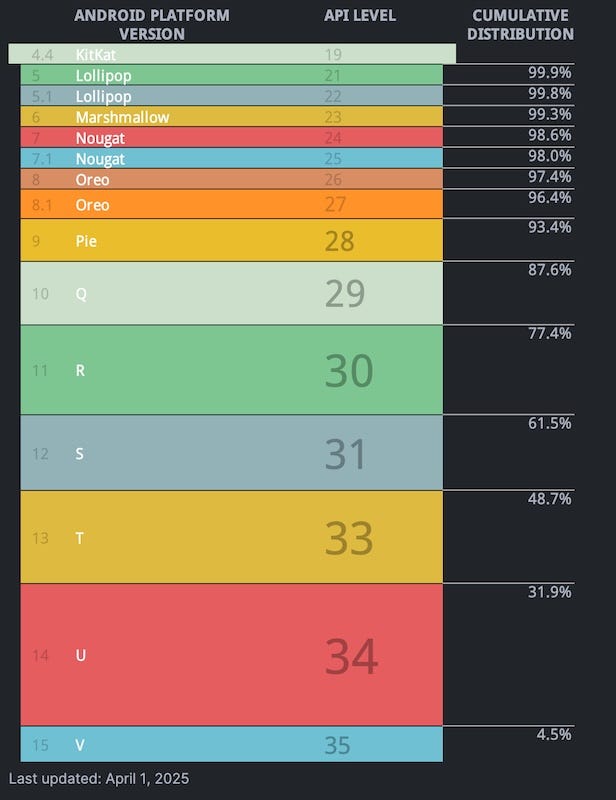
There is also a huge BUT: shaders are available from Android 13, so according to Android Studio OS distribution, roughly half of the devices will be able to support this approach. Of course, it will change over the time and I hope that we will be able to fully unleash the power of graphics programming with shaders!
Here’s my bento if you want to connect, chat and discuss!
메타데이터
- post_id
- e59216afd1e8
- slug
- gpu-accelerated-effects-glitch-at-scale-e59216afd1e8
- url
- https://medium.com/@konstantinzolotov/gpu-accelerated-effects-glitch-at-scale-e59216afd1e8
- canonical_url
- https://medium.com/@konstantinzolotov/gpu-accelerated-effects-glitch-at-scale-e59216afd1e8
- author_url
- https://medium.com/@konstantinzolotov
- status
- ok
- fetched_at
- 2026-06-15 20:49:13