EEPROM vs FRAM in Embedded Systems: Dumping and Correlating PoE Configuration on a Hikvision Switch
In my previous post, I explored how a Hikvision PoE switch stores its persistent configuration inside an external I²C EEPROM and how that…
EEPROM vs FRAM in Embedded Systems: Dumping and Correlating PoE Configuration on a Hikvision Switch
In my previous post, I explored how a Hikvision PoE switch stores its persistent configuration inside an external I²C EEPROM and how that data can be safely dumped and decoded.
Previous post: *Reverse Engineering I²C EEPROM Configuration on a Hikvision PoE Switch*
During that analysis, a second non-volatile memory device was identified on the same I²C bus: an **FM24C16 FRAM. This post focuses on dumping that FRAM, understanding why FRAM is used, and correlating its contents with the EEPROM configuration — particularly for PoE runtime behavior**.
Why FRAM Exists Alongside EEPROM
Embedded systems rarely use a single type of non-volatile memory. In this switch, both EEPROM and FRAM serve distinct roles.
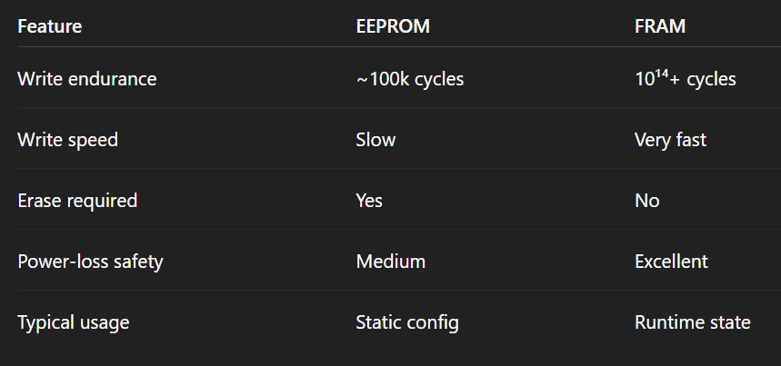
EEPROM VS FRAM Comparision
Key takeaway: FRAM is ideal for frequently updated configuration or state, while EEPROM is better suited for static, rarely changing parameters.
This design decision already hints that FRAM stores runtime or per-port operational data, not just board identity.
Identifying the FRAM on the I²C Bus
Running an I²C scan on the unpowered board (with external power applied):
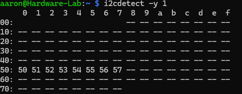
Scanning I2c BUS
50 51 52 53 54 55 56 57
This behavior matches the FM24C16 datasheet.
Why multiple addresses?
The FM24C16 uses part of the I²C slave address as memory address bits, exposing the FRAM as eight 256-byte pages:
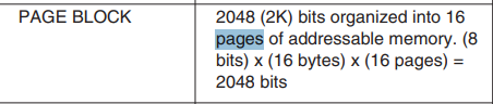
PAGE BLOCK
0x50→ Page 00x51→ Page 10x57→ Page 7
Total size: 2048 bytes (2 KB).
Hardware Setup and Pull-Ups (Important)
The PCB was not powered, so the SoC was not providing I²C pull-ups.
Required setup:
- External 3.3V supply
- Common ground with Raspberry Pi
- 4.7kΩ pull-up resistors on:
- SDA → 3.3V
- SCL → 3.3V
Without external pull-ups, reads were unreliable or failed entirely.
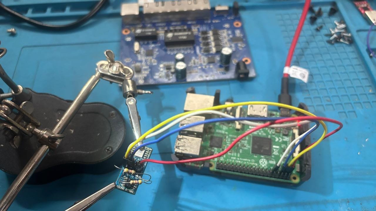
Connected and powered with Rpi3b+
Dumping the FRAM
To dump the full FRAM, each page must be read sequentially.
for addr in {0..7}; do
  for offset in $(seq 0 255); do
    i2cget -y 1 $((0x50 + addr)) $offset b \
      | sed 's/0x//' \
      | xxd -r -p >> fram.bin
  done
done
Result
Validating the Dump
Entropy analysis:

Entropy
Low entropy strongly indicates structured configuration data, not firmware, compression, or encryption.
Hexdump:
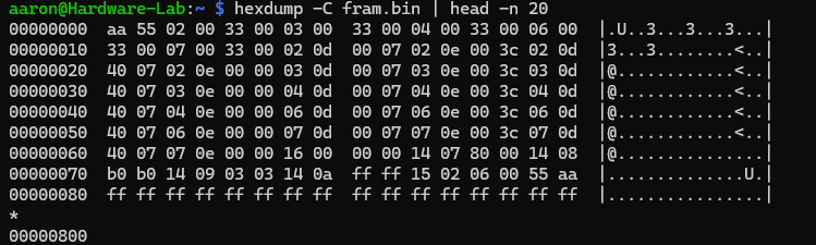
Hexdump
00000000 aa 55 02 00 33 00 03 00 33 00 …
Key observation
The FRAM begins with the same magic header:
AA 55 This is identical to the EEPROM header.
Conclusion:
Both EEPROM and FRAM are parsed by the same or closely related firmware logic.
Correlating FRAM with EEPROM
EEPROM (from previous post)
Stores:
Board ID
SKU / variant
Static PoE defaults
Manufacturing configuration
FRAM (this post)
Stores:
Per-port PoE mode
Per-port PoE power limits
Runtime placeholders
Example FRAM records:
02 0D 00 07 02 0E 00 3C 02 0E 00 00
Interpretation:
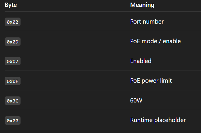
Interpretation
Why Power Limits Appear Twice
Each port contains two power-limit entries:
- Default-configured limit (e.g., 60W)
- Runtime value, initialized to zero
This is intentional.
Firmware behavior:
- Read Default config from EEPROM
- Initialize FRAM runtime structures
- Perform PoE negotiation
- Update runtime slots dynamically
FRAM’s high endurance makes it perfect for this purpose.
Decoding the FRAM: PoE Configuration Parser
A Python decoder was written to extract meaningful PoE configuration data.
Sample output:
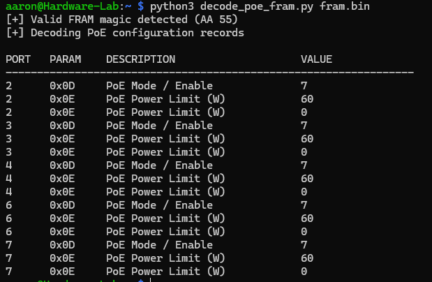
Decoded Fram Data
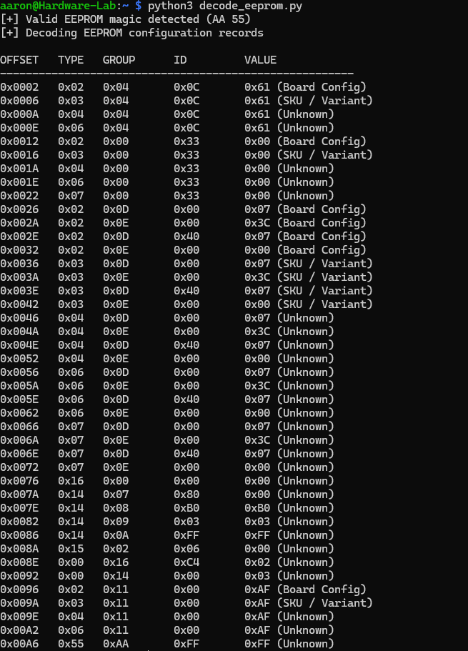
Decoded EEPROM Data
Security Implications
From a security perspective, this design raises important questions:
- No encryption observed
- No checksum or integrity verification visible
- Configuration trusted early during boot
- External writable FRAM on I²C bus
If FRAM is writable at runtime, this could enable:
- Persistent PoE misconfiguration
- Power abuse scenarios
- Configuration tampering across reboots
This pattern is common across enterprise networking devices and represents a valuable attack surface for hardware security research.
Conclusion
In this device:
- EEPROM defines what the device is
- FRAM defines how the device behaves right now
Understanding both is essential when reverse engineering embedded systems — especially networking and PoE-enabled devices.
This FRAM analysis completes the picture started in the EEPROM post and demonstrates how modern embedded designs split static identity from dynamic operational state.
메타데이터
- post_id
- e677d3f9efea
- slug
- eeprom-vs-fram-in-embedded-systems-dumping-and-correlating-poe-configuration-on-a-hikvision-switch-e677d3f9efea
- url
- https://medium.com/@aaronjjose/eeprom-vs-fram-in-embedded-systems-dumping-and-correlating-poe-configuration-on-a-hikvision-switch-e677d3f9efea
- canonical_url
- https://medium.com/@aaronjjose/eeprom-vs-fram-in-embedded-systems-dumping-and-correlating-poe-configuration-on-a-hikvision-switch-e677d3f9efea
- author_url
- https://medium.com/@aaronjjose
- status
- ok
- fetched_at
- 2026-07-15 22:13:45