How do I find the correct connection pins for an ESP32-S3 development board with an attached TFT…
This article is less of a tutorial than the result of a long search. When I first saw this development board on AliExpress seven months…
How do I find the correct connection pins for an ESP32-S3 development board with an attached TFT display (ST7789)?
This article is less of a tutorial than the result of a long search. When I first saw this development board on AliExpress seven months ago, I thought: Wow, what a great deal.
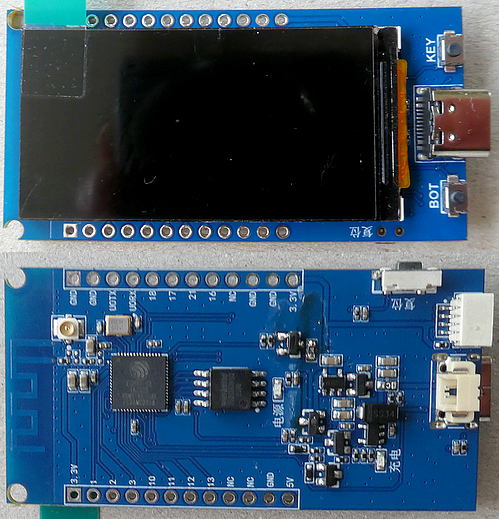
The board is equipped with an ESP32-S3 processor, which has 16 MB of flash memory and an additional 8 MB of PSRAM at its disposal. A 1.9-inch TFT display (ST7789 driver chip) with a resolution of 170x320 pixels is mounted on the development board. The board features a lithium-ion battery connector with an integrated charging circuit, two separate buttons, and a 4-pin JST-1.0 connector for 3.3 V, GND, and two GPIOs. At the time, all of this was available as a special offer for around 5 to 7 euros (Note: currently, the board costs roughly twice as much).
While the description section did list pin assignments, these referred exclusively to the processor’s externally routed GPIOs. Unfortunately, pin assignments for the onboard TFT display were missing. However, this couldn’t be too serious a problem, as **LilyGo** offers a very similar development board for sale:
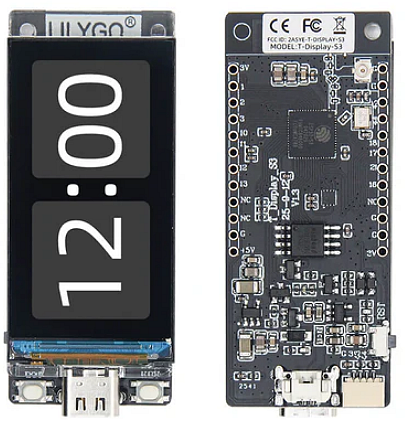
LilyGo provides information regarding the display’s pin assignments directly on the product page (there are two variants: with or without touch functionality):
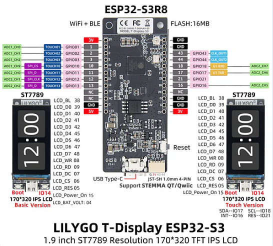
I simply assumed that this was a cheaper clone of the original board, and upon receiving it, I attempted to get it up and running with the display. The first hurdle was the fact that the display on the LilyGo board does not use a standard SPI interface, but rather an 13-pin parallel interface. Fortunately, the TFT_eSPI library offers a ready-made configuration (Setup206_LilyGo_T_Display_S3.h), but the screen remained blank.
Subsequently, I tried dozens of examples, but none of them could bring the screen to life; I was only able to verify the TFT backlight pin (GPIO 38).
Next, I attempted to trace the pins from the display back to the pins on the processor. To do this, I gently pried the display off the development board, to which it had been affixed with double-sided tape. However, I ran into a problem: these data lines were so fine that I was unable to map them using my test equipment. In the end, I was left with a ruined board, as I had evidently damaged one of the lines during my attempts.
Frustrated, I gave up and put the board into my parts bin, though I continued to browse listings on AliExpress in the hope that someone might provide a working pinout. The day before yesterday, the board fell into my hands again; and since I had, in the meantime, gained my first — mostly positive — experiences with artificial intelligence, I decided to ask it for a pinout. Unfortunately, my initial attempts proved just as frustrating as before. Naturally, the AI did come up with solutions — but they didn’t work.
When I mentioned the TFT backlight pin (GPIO 38), I was once again referred back to the LilyGo board. In the meantime, however, I had come to the conclusion that this display utilizes “merely” a standard SPI interface. Regarding this interface, I noticed that several pins bear the same names as those found on a typical SPI interface (DC, RST, CS, and Backlight). In addition to these, there are two further pins (WR and RD — write to and read from the display?) as well as the 8 data pins, D0 through D7. For the SPI interface, two pins still needed to be assigned: the “MOSI” and “SCLK” pins (and yes, there is also the “MISO” pin for directly reading out the display content, though this is rarely used). I decided to assign the WR pin as the SCLK pin, and the RD pin as the MOSI pin.
This assignment was ultimately the key to success, and for the first time, I was able to see an output on the display that I had programmed myself.
Here is the complete content of the TFT_eSPI User Setup file:
// ST7789 170 x 320 pixel
// using the default SPI lines
#define USER_SETUP_ID 810

#define ST7789_DRIVER     // Configure all registers

#define TFT_WIDTH  170
#define TFT_HEIGHT 320

//#define TFT_RGB_ORDER TFT_RGB  // Colour order Red-Green-Blue
#define TFT_RGB_ORDER TFT_BGR  // Colour order Blue-Green-Red

#define TFT_INVERSION_ON
//#define TFT_INVERSION_OFF
#define TFT_BACKLIGHT_ON 1

// define USE_HSPI_PORT for pins 10-13 and USE_FSPI_PORT for pins (34)-37
#define USE_HSPI_PORT    // HSPI
//#define USE_FSPI_PORT  // FSPI

// ESP32-S3        HSPI

#define TFT_BL 38 // LED back-light
#define TFT_BACKLIGHT_ON HIGH

#define TFT_CS     6
#define TFT_MOSI   9 // = SDA
#define TFT_SCLK   8
#define TFT_MISO   13 // Not connected

#define TFT_DC     7
#define TFT_RST    5 // Set TFT_RST to -1 if display RESET is connected to ESP32 board EN

#define LOAD_GLCD   // Font 1. Original Adafruit 8 pixel font needs ~1820 bytes in FLASH
#define LOAD_FONT2  // Font 2. Small 16 pixel high font, needs ~3534 bytes in FLASH, 96 characters
#define LOAD_FONT4  // Font 4. Medium 26 pixel high font, needs ~5848 bytes in FLASH, 96 characters
#define LOAD_FONT6  // Font 6. Large 48 pixel font, needs ~2666 bytes in FLASH, only characters 1234567890:-.apm
#define LOAD_FONT7  // Font 7. 7 segment 48 pixel font, needs ~2438 bytes in FLASH, only characters 1234567890:.
#define LOAD_FONT8  // Font 8. Large 75 pixel font needs ~3256 bytes in FLASH, only characters 1234567890:-.
//#define LOAD_FONT8N // Font 8. Alternative to Font 8 above, slightly narrower, so 3 digits fit a 160 pixel TFT
#define LOAD_GFXFF  // FreeFonts. Include access to the 48 Adafruit_GFX free fonts FF1 to FF48 and custom fonts

#define SMOOTH_FONT

//#define SPI_FREQUENCY        27000000
#define SPI_FREQUENCY        40000000
//#define SPI_FREQUENCY          80000000

// #define SPI_READ_FREQUENCY      6000000  // 6 MHz is the maximum SPI read speed for the ST7789V
// #define SPI_TOUCH_FREQUENCY  2500000
// #define SUPPORT_TRANSACTIONS
Update May 18th 2026: the TFT display is enabled by default when you power the device by USB, but when powering the device by battery the display will stay black until you enable the display by setting GPIO pin 15 to HIGH:
in header:
#define TFT_POWER 15

in setup():

pinMode(TFT_POWER, OUTPUT);
digitalWrite(TFT_POWER, HIGH);
Description of the Example Program
I display a Nixie-style clock on the screen. Each digit measures 80 pixels in width and 148 pixels in height, allowing the two-digit hours and minutes to fit onto the display. To indicate the seconds, I run a red bar along the bottom edge of the screen. The ESP32-S3’s time is synchronized via a Wi-Fi connection using NTP (Network Time Protocol). The screen brightness can be adjusted using the two buttons: the Boot button increases the display brightness, while the Key button decreases it.
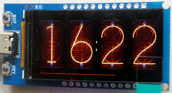
I obtained the image files for the individual digits from aly-fly’s repository and subsequently converted them into the respective header files using the RGB converter from mischianti.org.
In my tutorial “[Create a digital Christmas clock on an ESP32 with 1.9-inch display (small Cheap Yellow Display),](http://In my tutorial "Create a digital Christmas clock on an ESP32 with 1.9-inch display (small Cheap Yellow Display)," I provide a more in-depth explanation of the procedure.)” I provide a more in-depth explanation of the procedure.
These are the pin numbers for the two buttons and the Stemma QT/Qwiic connector:
Boot Button : GPIO 0
Key Button  : GPIO 14

QWIIC Connector seen from back side from left to right:
1 GND
2 3.3 V
3 GPIO 43 (labled U0TX)
4 GPIO 44 (labled U0RX)
You can find the example sketch in the subfolder “Esp32_S3_ST7789_1_9_NixieClock_v07” of the GitHub repository.
Connect a battery and measure the voltage
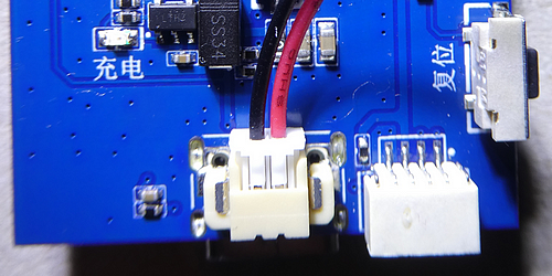
I have connected the lithium-ion battery to the development board with this polarity; however, you should use a multimeter to verify the polarity on your specific board to avoid a fire — or even an explosion — of your battery:
Measure the Battery Voltage
In the repository, you will find a small program located in the “Esp32_S3_ST7789_1_9_BatteryMeasurement_v01” folder that demonstrates how to measure the battery voltage and display it on the screen. GPIO 4 is used for this purpose; unlike with other development boards, the battery measurement does not need to be explicitly enabled beforehand or disabled afterwards.
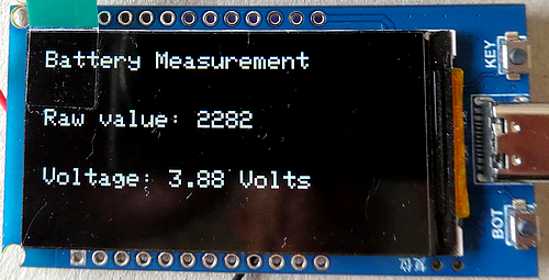
Battery Voltage Measure : GPIO 4Summary
I was extremely lucky to find the correct GPIO assignments for the display. Therefore, my advice to you is this: verify all pin assignments before purchasing, and if you are unable to determine them, do not buy this development board. In my experience, it is nearly impossible for us hobbyists to figure out the correct pin assignments after the fact.
Source code of the app
You find the complete code of the app, the modified TFT_eSPI library and the device-display settings file in my GitHub repositories.
Happy coding !
메타데이터
- post_id
- eb4bbbbac95b
- slug
- how-do-i-find-the-correct-connection-pins-for-an-esp32-s3-development-board-with-an-attached-tft-eb4bbbbac95b
- url
- https://medium.com/@androidcrypto/how-do-i-find-the-correct-connection-pins-for-an-esp32-s3-development-board-with-an-attached-tft-eb4bbbbac95b
- canonical_url
- https://medium.com/@androidcrypto/how-do-i-find-the-correct-connection-pins-for-an-esp32-s3-development-board-with-an-attached-tft-eb4bbbbac95b
- author_url
- https://medium.com/@androidcrypto
- status
- ok
- fetched_at
- 2026-06-26 21:52:29