L1 Diamond Stabilizer
Lagrange points L1, L2, and L3 are unstable, and that means some propellant is normally needed for station-keeping. This negatively affects…
L1 Diamond Stabilizer
Lagrange points L1, L2, and L3 are unstable, and that means some propellant is normally needed for station-keeping. This negatively affects sustainability, since an active system is needed to prevent what would be an eventual disaster. Because of that, if you ever built truly gigantic space habitats or infrastructure you would likely avoid those for fear of careening off into an unintended orbit, some of which are bad. This post describes an original idea for a space mega-structure which eliminates the need for propellant to stabilize within a certain control envelope.
Unstable points are appealing for the same reason they are unappealing. A wide range of orbits are reachable from Earth-Moon L1 (for example) with a very small Delta-V. This is likely even more true for L2. This is not true for L4 or L5. If you send something to the L4 point with a mass driver, it will likely arrive with 300 m/s or more. I illustrated this below with the family of orbits you get releasing something with small velocity from L1.
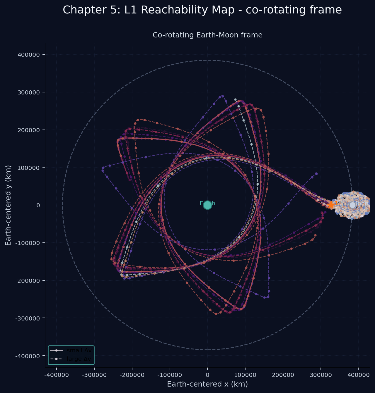
Orbits reachable by near-zero Delta-V from L1 in Earth-Moon system
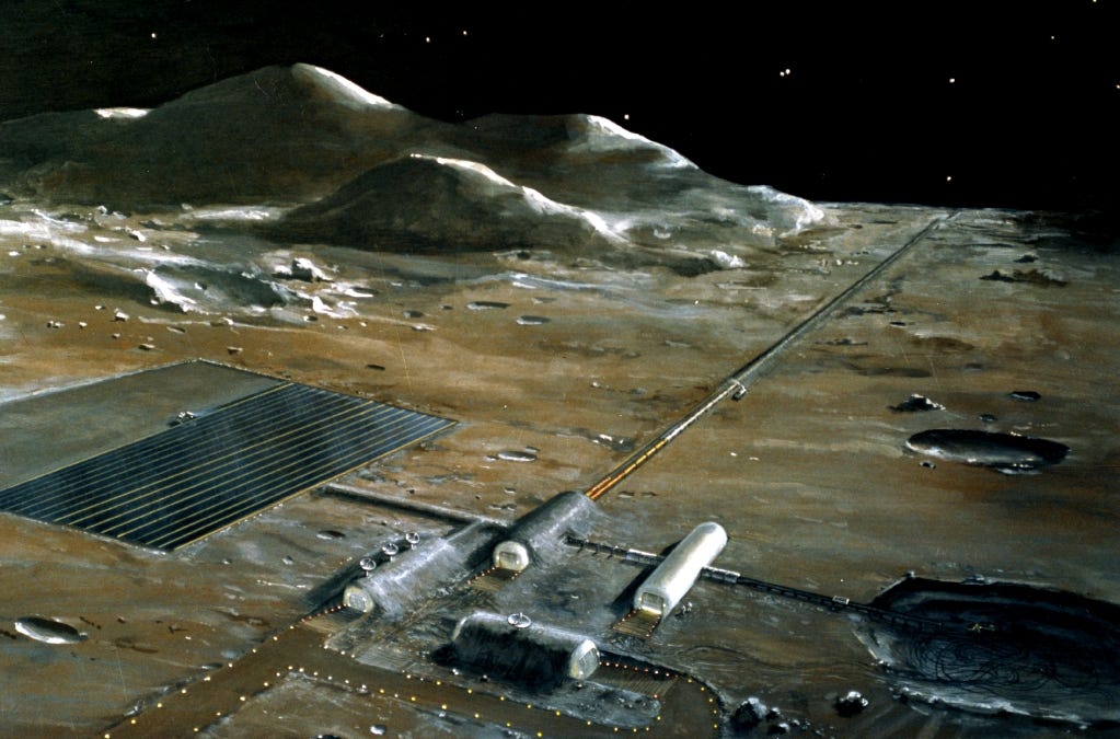
These don’t get you directly to LEO, but they span a fairly large number of interesting points. Again, these are essentially 0 Delta-V transfers, so it’s almost like a “free” transit map. What’s even more interesting is that you can reach the lunar surface… meaning that a mass driver and throw things from the lunar surface to your station. That means you can get mass from a surface into space infrastructure without rockets or high-velocity catchers. If you can do this, why do you even need a space elevator?
Space Tether Control, Generally
Aside from a space elevator, space tethers for transportation usually are modeled as “barbell”, a long tether with connected masses on either end. This is for a rotavator or a momentum exchange tether generally. Aside from catching and throwing payloads, there are various maneuvers possible by using control logic to extend and contract the tether so that it interacts with tidal forces of a planet. Those can be exploited to do certain maneuvers. I’ll show an example of this below for eccentricity pumping which demonstrates how messy these can be with a barbell.
The control scheme is that it contracts when moving away from the planet and extends when moving toward the planet (described in literature). However, it doesn’t work every pass due to chaotic factors of where its angular position lies at any given time. You could address this with the control system, not done here.
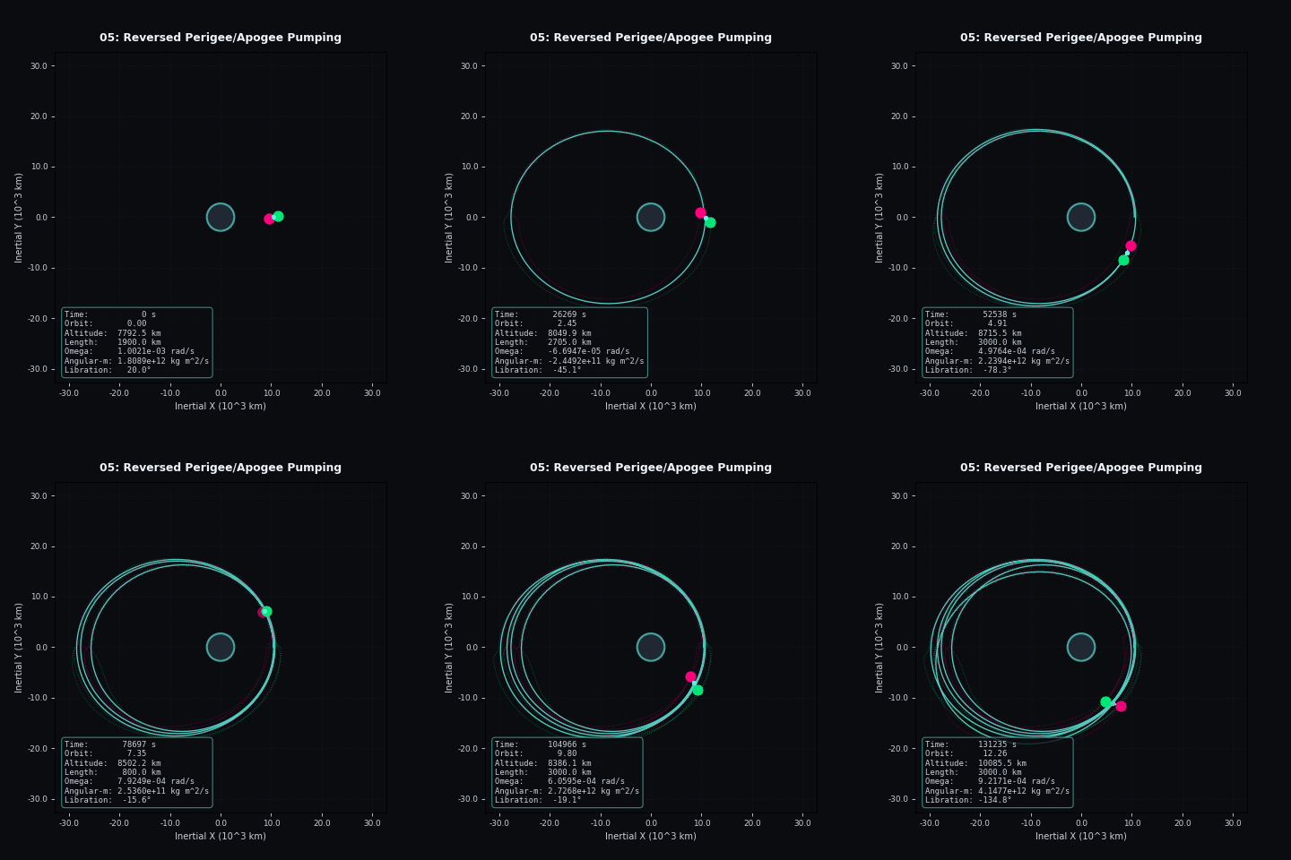
Eccentricity pump-down with barbell
But a lot of the “problems” with dividing out particular orbits can be fixed by using 4 masses in a quadrilateral instead of a barbell. I will show the same scenario here with those 4 masses and a control scheme that seeks to:
- Keep a constant moment-of-inertia of the whole system — thus control action does not directly change the rotation of the thing
- Keep the added tidal force constant when moving inward or outward by balancing the (distance)x(mass) from the line motion
That might be a bit technical, but solves the 2 degrees of freedom we have with the added masses and accomplishes a smooth control effect.
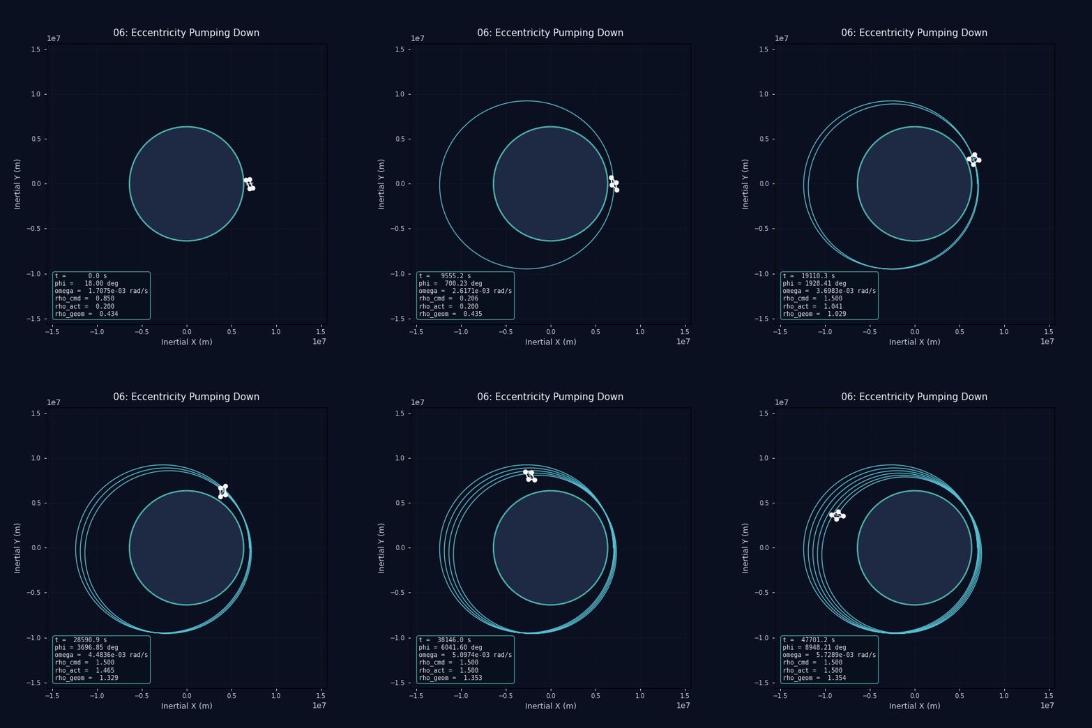
Common to all simulations with this control scheme, it looks like a square is rotating in 3D space, out of the page (it is still 2D). You can see extremely consistent evolution of the orbit, unlike the barbell case. This is a very strong result, and I think you would be hard pressed to ever get anything like this with a barbell no matter what control scheme you use. 4 masses are simply better than 2 because you have more degrees of freedom.
This still has an imperfection that the quadrilateral (parallelogram in this control scheme) will tend to gain rotational speed over time. This might be correctable with the control scheme, but for my purposes at the given moment, this is an unwanted artifact, and I’m just leaving it in.
You can find these all described in the repo where I have these coded (AI assisted), with a lot more scenarios to watch. All those videos really help to give better intuition of these dynamics.
Tidally-Locked Diamond
The prior 2 cases are for the “tumbling” in orbit scenario. You can imagine another case where, instead of tumbling, you stay tidally locked. That doesn’t work with changing eccentricity, but it does work for the case of maintaining stability around unstable Lagrange points.
This vague form of this idea has nagged at me for almost a decade, and I’ve made a home page for the idea here:
[embed]AlanCoding (github) homepage Homepage for the L1 diamond stabilizer concept.alancoding.github.io
I’ve only just now gotten around to getting real legitimate simulations. In the next animation we have a velocity perturbation in an unstable direction → towards the moon. The control scheme is only focused on 1 degree of freedom:
- As the structure moves towards the moon, pinch inward in the Earth-moon line
- As the structure moves towards the Earth, stretch outward in the Earth-moon line
- Through all of this, keep total moment of inertia constant
- Add some dampening so that oscillations decrease overtime
This is the most exciting of the scenarios I drafted, where the perturbation is only just within the stability envelope.
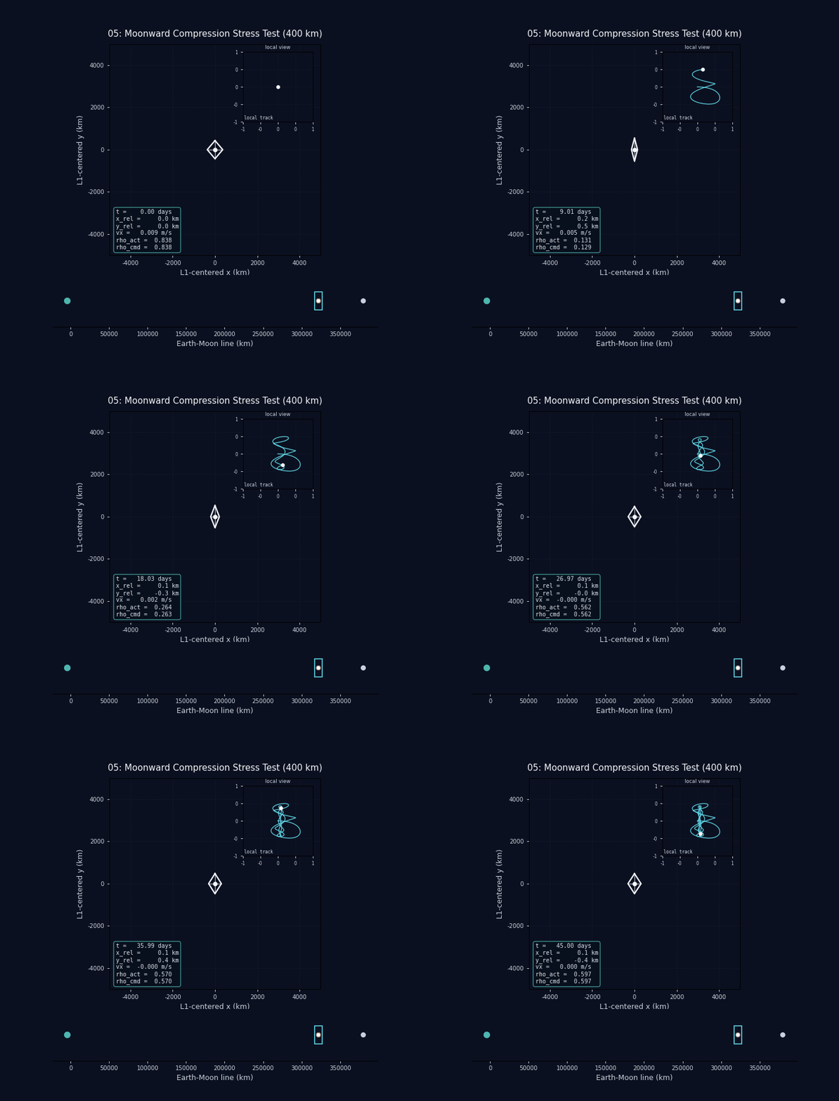
Moonward velocity perturbation, and control scheme stabilizing that
To simplify:
- the x-axis is the Earth-moon line
- the y-axis is perpendicular to that line
- Yes, that means that the reference frame shown above is actually rotating
It is important that the shape is a diamond (has 4 masses) because that allows it to keep its rotation constant. So its orientation does not change relative to the Earth and the moon. This keeps the control system simple, and avoids being caught in a state where our ability to respond might be compromised (like a barbell could be). Having the tidally locked position also seems intuitively important to me for having stable docking with spacecraft and the general usefulness of the station.
Space Industry Consequences
So let’s get to the dreamy stuff. How would/could this actually be used? The 4 masses will see some acceleration. So you might take either routes:
- Add a mass in the center which is your “action habitat” or station, so that it exists in near micro-gravity and only rotates 1 per month, or has completely non-rotating station
- Have habitats themselves be the movable masses and accept some acceleration will happen
The problem with the 1st option is that it limits your control authority. So ideally you want the 4 moving masses to be a significant fraction of the station’s overall mass. But this isn’t necessarily required because it is a balance between mass requirements versus degree of precision. But we need to formalize the control envelope to make that concrete.
Control Envelope (from simulation discoveries):
- Tolerable speed deviation: 0.009 m/s
- Tolerable positional deviation: 600 meters
What happens when you go outside of the control envelope? The station “squishes” totally vertically, and then there’s no more additional acceleration it has to offer. If you are still accelerating towards the Earth or the moon, then there is no stopping that deviation, so you fly off of the unstable point, as it is unstable. The speed deviation is very low, but I would point at the positional deviation and note that we have essentially centimeter-scale tracking of satellites today. The non-circularity of the moon’s orbit and the sun’s tidal effects would all matter is a real system design. But the general principle, I think, still holds.
Next important point is that the control action pulls opposite masses and pushes the other pair of opposite masses. This means that the structure can not strictly be a tether. It would be realistic to imagine it as a tensegrity structure, where there are both rigid and tether parts to it. The structure is still controlled by winches.
Given that we would need both push & pull forces, and the side length is 400 km, I realize, that is a bit of a tall order. I still think it’s more realistic than a space elevator. However, the size trades off with the control envelope. If you made the sizes 5,000 km, then you will have a positional envelope of around 500 km, which is to a significant fraction of the structure’s size itself.
My excitement around the idea is that it could couple well with a lunar mass driver. Almost all conceivable uses of a lunar mass driver (see the Anthrofuturism youtube) involve mass-manufacturing rockets on the moon. For what we know right now, I think it’s also worth considering architectures where we can use a mass driver to deliver mass to space with essentially no purpose-built rocket engines. In the idealized problem, a payload launched from the lunar surface can reach the L1 station with literally 0 m/s velocity. Obviously this requires really good precision…
But just consider how much better this is than the alternatives. There is no rocket equation applied. You catch 100% of the mass you launch, and you do so at an absurdly gentle speed for the catcher. This basically one-shots the problem of how to coordinate the mass-driver with the rest of orbital infrastructure. Because whatever momentum you absorb from the catch will then be quickly canceled out by the stabilizing controller. Once you get moon rock to the L1 station, the whole cislunar system is your oyster! It is a fantastic jumping-off point to other destinations.
AI Use
The repo linked has the source code for the gifs, and numerical findings, which was written using codex gpt-5.4-mini. Although, by the time I was ever putting it into codex, I had the clear shape of the idea extremely clear.
메타데이터
- post_id
- ecc02853108f
- slug
- l1-diamond-stabilizer-ecc02853108f
- url
- https://medium.com/@alanse/l1-diamond-stabilizer-ecc02853108f
- canonical_url
- https://medium.com/@alanse/l1-diamond-stabilizer-ecc02853108f
- author_url
- https://medium.com/@alanse
- status
- ok
- fetched_at
- 2026-06-29 01:02:39