FT232H with IS31FL3731
HID with Charlieplexing IC
FT232H with IS31FL3731
HID with Charlieplexing IC
Charlieplexing
Charlieplexing is an interesting technique to drive lots of LEDs with smaller number of output lines. The idea is very simple, given two output lines, you can drive two anti-parallel LEDs, in a circuit like the following.

Two output lines Charlieplexing (from Wikipedia)
X1 = positive and X2 = negative lights up LED1; X1 = negative and X2 = positive lights up LED2. If you need both LEDs to light up, just time-division multiplexing the positive and negative signals on X1 and X2, which flashes LED1 and LED2 fast.
Given N output lines, pick any pair of two lines to place two anti-parallel LEDs, you can drive total of N * (N-1) LEDs.

IS31FL3731 IC uses two sets of 9-pin output to drive maximal 2 x 9 x 8 = 2 x 72 LEDs = 144 LEDs. The LED matrix can be arranged into 9 x 16 shape as follows.

For example, eight LEDs in a row, are cathode connected to CA1, whose anodes are coming from other outputs CA2, CA3, …, CA9. The same is true for other rows. For example, CA6 will have LEDs from CA1, CA2,CA3, CA4, CA5, CA7, CA8, CA9 pointing towards it.
We will use a 144-LED matrix from Adafruit (link), which has the LEDs already wired properly like this. BTW, there are other less LED counts matrix from Adafruit (link). Once you understand the principle of Charlieplexing, you can figure out arrangements to skip rows and columns, but still use IS31FL3731 to drive the LED matrix.
Imagine a common cathode or common anode scanning array approach, such as TM1637/HT16K33/MAX721, it needs 9 + 16 = 25 output pins for example to drive a 16x9 LED matrix.
Well, IS31fl3731 is not that impressive in reducing number of IO lines, since it uses 18 output pins (CA1…CA9 + CB1…CB9), instead of 25 outputs from a scanning approach.
In fact, if the IC designers really stick with charlieplexing, they can arrange the LEDs into 17 x 16 = 272 LED matrix, and only drive them with 17 output lines.
So that’s one less IO line, but almost twice the number of LEDs to drive.
Let’s read the datasheet
We will use the IS31FL3731 breakout module + 144-LED matrix from Adafruit (link). It comes with lots of library code (Python, Arduino etc.) and nice example code. It makes hardware prototyping very easy.
Well, the goal of my hardware prototyping articles is focused on reading, testing and learning from device datasheets directly.
Hardware datasheets are just like software API documents. They contain wealth of information. The downside is that sometimes the information is laid out flat, not much operational knowledge such as steps to bring things up in the right order.
To use an analogy to real life example, it’s a bit like being presented with a map of a new city. The map details everything everywhere. But you can quickly get lost, while exploring a new city without a local guide. Because the map doesn’t show you the operational knowledge of living in that city.
So let me try to be your local guide and walk you through the fun of exploring the city of IS31FL3731 (datasheet link) briefly.
Just a reminder of a few common hazards of exploring new hardware components before we hit the road:
- signals or power pins connected improperly (polarity flipped for example)
- ESD damage to the component
- get a bad/wrong component to begin with (digikey sent me wrong component one time)
- mis-read or mis-understand the datasheet
The list can go on and on. That’s why hardware interactive development (HID) is so important. You get immediate feedback to check your work/assumptions about the hardware piece before moving on to the next step.
FT232H I2C Jupyter Notebook
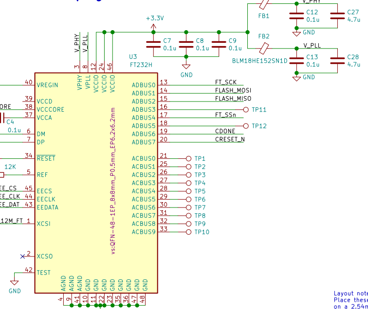
For FT232H I2C pinout, please check my earlier articles. Simply connect SDA, SCL and the power, ground wires to Adafruit IS31FL3731 breakout module. The I2C pull-up resistors are included on the breakout module already (schematic link).
Let’s jump into the Rust kernel Jupyter notebook.
[embed]
Summary
- The goal of HID is to quickly explore hardware features with minimal incidental complexity.
- IS31FL3731 has this tricky two layered addressing scheme, which was named different on other devices. But the idea is the same, because it supports auto-address-increment of batch register write, the first byte would be a register address (pointer) and subsequent bytes has to be all interpreted as data bytes to fill the subsequent registers. If you have two layers of addresses, you have to separately send them in two I2C START/END section. That’s not explicitly mentioned in the datasheet.

Now it’s time to unfold the map (data sheet link) and explore on your own.
메타데이터
- post_id
- f2f78c9caef0
- slug
- ft232h-with-is31fl3731-f2f78c9caef0
- url
- https://medium.com/swlh/ft232h-with-is31fl3731-f2f78c9caef0
- canonical_url
- https://medium.com/swlh/ft232h-with-is31fl3731-f2f78c9caef0
- author_url
- https://medium.com/@circuit4us
- status
- ok
- fetched_at
- 2026-07-28 17:01:39